
Abstract
In-pipe robots are usually used to carry many kinds of equipment to operate in the pipeline. In this article, a novel self-locking mechanism for continuous propulsion inchworm in-pipe robot is proposed. The constant power and continuous locomotion principle is obtained by upgrading the traditional pipeline robot. The structure of the inchworm in-pipe robot is designed including self-locking mechanism and telescopic mechanism. The operating principle of self-locking mechanism is analyzed for parameter design and performance evaluation. A new type of hydraulic cylinder series circuit is introduced, which realizes synchronous motion in the related mechanisms of pipe robot. And the dynamic characteristics of the hydraulic cylinders are analyzed and simulated to verify feasibility of the circuit. The prototype is developed to prove that the novel inchworm in-pipe robot can adapt to diameter of 140–180 mm pipe and has 550 N traction ability with the average speed of 0.11 m/s.
Keywords
Introduction
With the extensive application of pipeline system, the pipeline problems including detection and maintenance are becoming more and more prominent. In order to solve difficulty and danger in pipeline operation, the in-pipe robot provides an effective technology approach.1,2 Recently, bio-inspired robots have developed rapidly, and researchers begin to study the way of in-pipe robot moving from the bionics perspective.3–5 Many kinds of in-pipe robots are developed including mantis robot, spider robot, snake robot, and inchworm in-pipe robot.6–8
German scholar B Yi developed the MAKRO system for multi-joint worm pipeline system. MAKRO is composed of six body units, and the head and tail are exactly the same two units. Driven by three motors between the nodes, MAKRO can lift or bend its body to get over obstacles and turn a corner. 9 Strefling invented fish-fin tube robots that are made up of body and tail fins, which are iron–elastic materials. Under the influence of the external magnetic field, the elastic fins oscillate, causing a vortex in front of the body and pushing the body to move forward. 10 Zagler has developed the spider pipeline robot MORITZ. The robot has eight crawling drive feet and its driving capacity is 150 N with a maximum speed of 0.1 m/s. However, its control is too complex and the drive efficiency is too low. 11 Schlumberger tractor is an inchworm in-pipe robot which is applied in oil well. Its structure is characterized by the use of three clawing arms, which can be automatically centering and holding the inner wall. The robot has powerful traction, but it grows longer and reduces flexibility.12,13
The main application of in-pipe robot researched in this article is large-diameter pipeline such as oil well, natural gas, and nuclear power pipeline. The comprehensive literature shows that the inchworm in-pipe robot is the most suitable one because of the simple structure and the large traction capacity. 14 However, the disadvantages of traditional in-pipe robots are large size, lack of traction, and discontinuity of motion. Therefore, it is of great significance to develop an in-pipe robot with miniaturization, large traction, and fast movement.15,16
In this article, a novel self-locking mechanism for continuous propulsion inchworm in-pipe robot is proposed, by imitating motion principle of inchworm and upgrading traditional in-pipe robot. On the basis of analysis for continuous walking principle, the structure of in-pipe robot is designed and analyzed. The hydraulic system is planned with the hydraulic cylinder series synchronous circuit and its dynamic characteristics are analyzed and simulated. The robot indexes of “miniaturization, large traction, and fast moving” are tested by developing prototype and experimental system.
Locomotion principle and structure
The motion of inchworm is a kind of periodic peristaltic crawling, and peristaltic attitude presents a certain regular changes.17,18 The front and the rear feet act as a retainer to maintain a different relationship with land corresponding to different stages, while the trunk portion acts as a tractor. Imitating the motion of inchworm, in-pipe robot adapts the approach that the front and the rear parts are fixed alternately and realizes motion by the middle-part extension and contraction.19,20
Locomotion principle of traditional inchworm in-pipe robot
The structure of traditional inchworm in-pipe robot generally includes three parts: the front and the rear parts serve as locking mechanism and the waist acts as telescopic mechanism. The locomotion principle is shown in Figure 1.
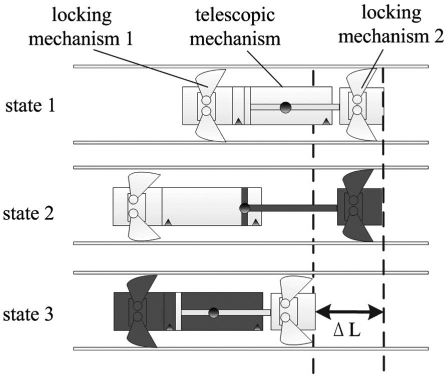
The locomotion principle of traditional inchworm in-pipe robot.
State 1 is the initial state of the robot, and two locking mechanisms and telescopic mechanism contract simultaneously. In state 2, the locking mechanism 2 expands to lock the inner wall and then telescopic mechanism stretches to realize the forward motion of robot. In state 3, the locking mechanism 2 retracts to unlock from the inner pipe wall. Meanwhile, the locking mechanism 1 expands to lock the inner wall. Then, the telescopic mechanism contracts, dragging the locking mechanism 2 back to the initial state. In the above cycle, the robot can accomplish the forward motion in the pipeline.
However, the traditional inchworm in-pipe robot has the following defects:
The length of the robot changes during the motion, resulting in the reciprocating motion of the robot’s mass center (solid dot in Figure 1), which affects the motion stability of the robot.
The displacement of a motion cycle is
During state 2, the telescopic mechanism propels the locking mechanism 1 forward, thus the required power is small. During state 3, the telescopic mechanism tracts the locking mechanism 2 and loads, thus the required power is larger. Robot working power changes over a wide range, which is unfavorable for the stability of the drive system.
Locomotion principle of novel inchworm in-pipe robot
Aiming at solving the shortcomings of the traditional inchworm in-pipe robot, the original structure is improved, and the continuous propulsion inchworm based on self-locking mechanism in-pipe robot is proposed. As shown in Figure 2, the continuous propulsion in-pipe robot is composed of telescopic mechanism 1, self-locking mechanism 1, telescopic mechanism 2, and self-locking mechanism 2.
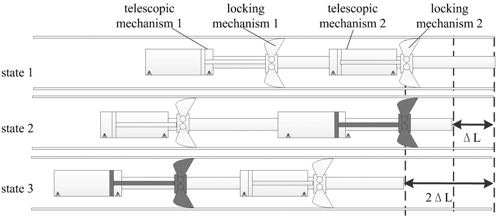
The locomotion principle of continuous propulsion in-pipe robot.
The locomotion principle is as follows: state 1 is the initial state of the in-pipe robot, the two self-locking mechanisms and telescopic mechanism 2 are in the contracting state, and the telescopic mechanism 1 is in an extending state. In state 2, the self-locking mechanism 2 expands to lock the pipe wall. The telescopic mechanism 2 extends and the robot body moves to the left under the reaction force. The telescopic mechanism 1 contracts so that the self-locking mechanism 1 moves forward. In state 3, the self-locking mechanism 1 extends to lock the inner wall of the pipe. The telescopic mechanism 1 stretches to drive the entire frame to move; and at the same time, the telescopic mechanism 2 contracts so that the self-locking mechanism 2 moves forward. After accomplishing the actions in state 3, the in-pipe robot returns to its original state.
Compared with the traditional inchworm in-pipe robot, this novel in-pipe robot has the following advantages:
The displacements of the robot in states 2 and 3 are
The required power of the novel in-pipe robot in the work remains the same, which is conducive to the drive system to work efficiently and steadily.
The self-locking mechanisms move symmetrically relative to the centroid, so the mass center position of novel robot remains unchanged, which is beneficial to the robot’s attitude stability.
Structure of the novel in-pipe robot
According to the principle of continuous locomotion, the structure of the inchworm in-pipe robot is designed. As shown in Figure 3, the structure is composed of two identical modules, and the module is bolted to another. Each module consists of three parts: frame, telescopic mechanism, and self-locking mechanism. The telescopic hydraulic cylinder enables the in-pipe robot to move forward, and the locking hydraulic cylinder is responsible for the expansion and constriction of the self-locking mechanism.

Structure of the continuous propulsion in-pipe robot.
The design of the self-locking mechanism is illustrated in Figure 4(a). The self-locking mechanism is composed of frame, locking hydraulic cylinder, and cam self-locking mechanism which ensure robot traction exceeds the locking force. As shown in Figure 4(b), the cam self-locking mechanism mainly consists of a locking cam, two guide wheels, a guide plate, and a connecting rod. Three sets of connecting rods are regularly arranged on the circumference of the two bases. One base is fixed with the frame, and the other one can slide relative to the frame.

Components of the self-locking mechanism: (a) design of self-locking mechanism and (b) cam self-locking mechanism.
The working principle of the self-locking mechanism is that the hydraulic cylinder drives the moveable base left or right relative to the frame. When the piston rod of the hydraulic cylinder is pushed out, the connecting rod enables the guide plate to expand in the radial direction. Under the action of the guide wheel, the cam gets a compression with a proper attitude. After three sets of cam locking mechanisms are all in contact with the pipe wall, the hydraulic cylinder will also maintain a certain amount of pressure, so that self-locking mechanism can adapt to diameter change.
Analysis of cam self-locking
One-way cam self-locking is based on the principle of cam locking, which is used in the self-locking mechanism of in-pipe robot.
The core function of self-locking mechanism is reverse locking. When the robot moves in one direction, cam self-locking can prevent robot body to shift in the opposite direction through producing large friction between the cam and pipe wall. The principle of cam self-locking is shown in Figure 5.

Diagram of cam self-locking principle: (a) state of moving to the left and (b) state of moving to the right.
In Figure 5, point O is the rotation axis with a torsional spring and the cam contacts with inner wall on point A. The torque of torsional spring for the cam is M, whose direction is shown in Figure 5.
When robot is moving to the left, cam has the trend of movement to the same direction and the friction of the cam is to the right. As cam will move clockwise around the point O, the radius contacting of the pipe wall is reduced, the positive pressure
From the above analysis, the mechanism can only move in one direction when the shape of cam profile and the friction coefficient satisfy the principle of self-locking.
The forces on the cam are analyzed below, the moment balance equation at point A is

where
Force balance equation of the cam in the vertical direction is

According to the formula of friction

Combining equations (1)–(3)

The result of cam self-locking is that no matter how much
The cam profile adapt to pipe diameter variation is designed below. An equivalent simplification of the motion pair on cam and pipe wall is built. The motion of the cam on robot is equivalent to the planar cam mechanism with the flat-bottom moving part, and the change of the pipe diameter can be equivalent to the vertical displacement of the moving part shown in Figure 6.
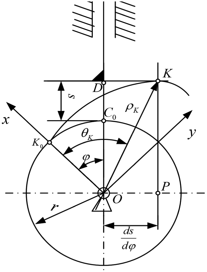
Schematic diagram of cam profile.
According to the rule of cam motion


In order to satisfy the self-locking conditions of the cam

Take the limit

Differential equation is obtained

Initial conditions:

In order to analyze the relationship between the pressure F subjected to the cam and radial compression

Mechanical model of cam.
In Figure 7, the dotted line represents the position that the cam is not affected by the pressure F of the pipe wall, which is called the cam unforced state. At this point,

When affected by the pipe wall pressure F, the cam revolves by an angle

By equations (11) and (12)

When the cam is in the unforced state, the torsional spring makes the short side of the cam horizontal to the bottom of connecting rod. The torsional spring has a compression relative to its free state, and the compression angle is

Substituting

By equations (13) and (15), to eliminate intermediate variable

Formula (16) is the model expression of the cam. The analysis of locking principle and modeling of cam can be used to make parameter design and performance evaluation of cam locking mechanism.
Design of hydraulic system
Because of the continuous propulsion on inchworm in-pipeline robot hydraulic drive, the two hydraulic cylinders of telescopic mechanism of robot need synchronization to achieve the optimal traction capacity. In this article, synchronization method is proposed in which hydraulic cylinder chambers with rods are connected to satisfy the requirements of speed synchronous and opposite directions. Due to the cylinder leakage, each reciprocating motion will increase the two cylinder position error, so the dynamic compensation of the circuit fluid is required in the hydraulic system.
Hydraulic drive system
Hydraulic drive system is shown in Figure 8, mainly divided into five parts:
Power source: small pump station 1 driven by motor gear;
Control components: safety valve 2, back pressure valve 3, main control valve 4 for telescopic hydraulic cylinder, main control valve 5 for compensation and discharge circuit, stack check valve 6, control valve 7, and control valve 8;
Actuators: telescopic hydraulic cylinder 9, telescopic hydraulic cylinder 10, locking hydraulic cylinder 11, and locking hydraulic cylinder 12;
Auxiliary components: series pipelines 13, tubing, pressure gauges, and pipe joints;
Hydraulic oil.

Schematic diagram of hydraulic drive system.
The working principle of hydraulic drive system is as follows: the small pump station 1 provides pressure oil for the drive system; locking hydraulic cylinders are controlled by the control valve 7 and control valve 8, to achieve the expansion and the constriction; the hydraulic cylinder series synchronous circuit is formed through connecting the two drive hydraulic cylinder chambers with rod by series connection 13; the compensation and discharge functions are achieved by the main control valve 5 and hydraulic control check valve in series. The control valve 4 controls action and direction of series synchronous circuit of the hydraulic cylinder to realize continuous motion of inchworm in-pipe robot.
Dynamic of series circuit
The series circuit dynamic of the two telescopic cylinders on the pipeline robot are analyzed below, and the model of propulsion load is shown in Figure 9.

Model of propulsion load.
To the telescopic hydraulic cylinder 1 and 2, the following relationship exists


where
Assuming that the leakage coefficients in the two hydraulic cylinders are equal:

At this point, the two cylinders can ensure synchronization, no matter what the load is.
When considering the leakage and the hydraulic system is in steady state, the following equation is derived from equation (20)

If

As

Reaching steady state, the pipeline pressure of the series circuit is got from the formula (24)

As

Considering the case of internal leakage, the condition of steady state of series circuit is obtained

As hydraulic series circuit always operates in the left eccentric state, that is
Assuming the piston movement is uniform linear motion during the hydraulic cylinder operation, the following equation is derived from equations (17) and (18)
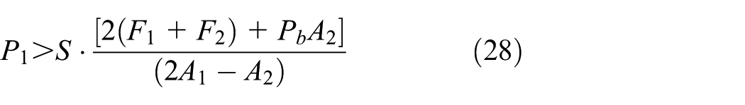
where S is the safety factor.
In summary, when considering the leakage, if the hydraulic drive system can meet the conditions described above (equation (27)), the inchworm in-pipe robot can ensure accurate synchronization and smaller cumulative error. The choice of working pressure shall be in accordance with the results of formula (28). In order to be able to select smaller working pressures and larger partial loads, a smaller back pressure
Simulation and experiment tests
Simulation and discussion
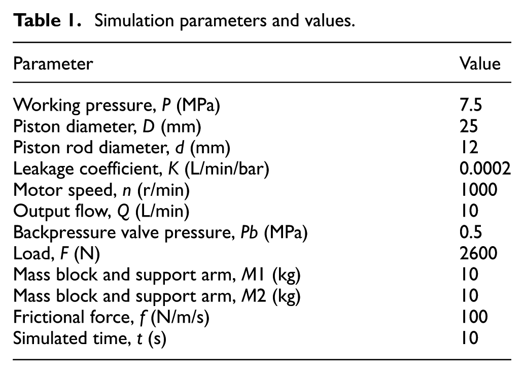
The hydraulic system series synchronous circuit is simulated by AMESim, and the main simulation parameters and values are shown in Table 1.
Simulation parameters and values.
Hydraulic cylinder working condition
In simulation, the operations of telescopic hydraulic cylinder 1 and telescopic hydraulic cylinder 2 are investigated. Because the hydraulic cylinder 1 and the hydraulic cylinder 2 are alternately symmetrical, the working conditions are basically the same. Hydraulic cylinder 1 is selected as the research object.
The working pressure of hydraulic cylinder 1 is shown in Figure 10(a). The test shows that the hydraulic drive system works normally under the periodic load bias condition. It can be seen that the working pressure reaches the dynamic balance in the short time in one operation, which proves that the theoretical calculation method can be used in the series synchronous circuit.

Curves of hydraulic cylinder working condition: (a) working pressure of hydraulic cylinder 1 and (b) internal leakage flow of hydraulic cylinder 1.
The internal leakage flow of hydraulic cylinder 1 is shown in Figure 10(b). The leakage flow of hydraulic cylinder 1 tends to be two-way symmetrical with the pressure increasing in series circuit, which makes the maximum pressure in series circuit gradually tends to be constant.
Motion synchronization
The displacement curve and the velocity curve of mass block M1 and M2 of inchworm in-pipe robot locking mechanism are shown in Figure 11.

Motion curves of mass block M1 and M2: (a) displacements of mass block M1 and M2 and (b) velocity of mass block M1 and M2.
The motion curves prove that the mass block M1 and M2 are driven by the hydraulic system, and the displacement and velocity are almost completely synchronous and backward, which can meet the design requirements that the operation is stable without mutation and the cumulative error is small.
Discussion of simulation
The continuous propulsion inchworm in-pipe robot can operate stably when driven by the hydraulic system and conforms to the requirements including high traction and fast moving;
The robot’s working efficiency and energy efficiency is improved because the input and output power of the hydraulic system is basically constant;
The two hydraulic cylinders have the rod cavity in series, which can be used as the new hydraulic series circuit to realize synchronous and reverse motion. It has the advantages of high synchronization precision, simple control, and high dynamic stability.
Experiment and discussion
According to the above design and analysis, the prototype of continuous propulsion inchworm in-pipe robot is developed, as shown in Figure 12. The robot is driven by hydraulic pressure and adopts cam locking mechanism to realize continuous locomotion in the pipeline.

Prototype of continuous propulsion inchworm in-pipe robot.
The structure of cam locking mechanism is shown in Figure 13. The connecting rod, guide wheel, cam, and guide board are all made of stainless steel, ensuring high strength and long life. A set of locking mechanism consists of three cam locking modules, distributed on the axial circle.
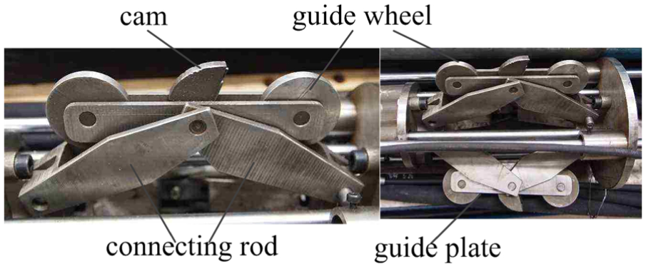
Structure of cam locking mechanism.
The maximum diameter of the locking mechanism is 190 mm and the minimum diameter is 136 mm, which meets the design target diameter of 140–180 mm.
The experimental system of the robot is shown in Figure 14. During the test, the process initialization of hydraulic drive system shall be first completed. After the locking mechanism of the pipe robot is recovered, the robot can be put into the tube to do the experiment.

The experimental system of the robot.
Experiment shows that inchworm in-pipe robot operates normally in 10 min, and two telescopic mechanisms realize synchronous movement without cumulative errors. At the same time, the average speed of robot motion is 0.11 m/s. The speed limit of robot lies in hydraulic valve switching frequency and the flow rate of the pump station.
The maximum traction of inchworm in-pipe robot is measured in the test process shown in Figure 15. The method of testing locking force is that making the locking mechanism hold the pipe wall and pulling the robot in the opposite direction. When the robot is almost sliding, the maximum locking force is obtained. The way of testing the robot traction capacity is that making the tail of the robot and electronic measurement fixed up and measuring the traction value as robot moving forward.
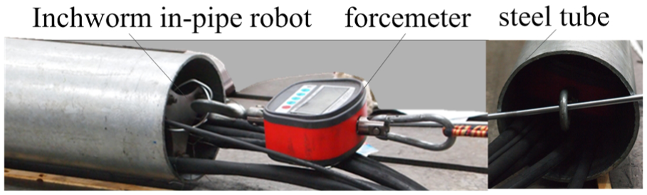
Test of traction and locking force.
The test shows that after locking the inner wall of pipe, the locking mechanism can keep lock state as the external pressure of 568 N is applied. During the movement, the maximum traction force reaches 550 N. However, the traction does not exceed the locking force according to the previous design. The reason is that the hydraulic drive system has no self-locking function. As the force of the cam self-locking reaches a certain value, connecting rod of locking mechanism produces deformation, reducing the self-locking force. So, the next step is to design hydraulic self-locking device to improve robot’s traction capacity.
Conclusion
Based on the motion principle of traditional inchworm in-pipe robot, the continuous propulsion locomotion principle is put forward. The structure and hydraulic drive system of novel inchworm in-pipe robot are designed, and dynamic characteristics of the series synchronous circuit in the hydraulic system are analyzed. Then, the simulation of the hydraulic drive system is completed to prove the validity of theoretical analysis. Finally, the performance index of the robot is carried out through the prototype and experiment platform, which basically meets the design requirements of “miniaturization, large traction, and fast motion.” It is concluded as follows:
Based on the analysis of locomotion principle and structure, prototype is developed which has the capability of adjusting the pipe diameter of 140–180 mm.
The locking function of cam self-locking mechanism is operating, and the locking force can be guaranteed for 586 N.
The inchworm in-pipe robot can realize the continuous movement by the speed of 0.11 m/s, which is twice as fast as traditional telescopic.
The hydraulic cylinder series circuit applied in hydraulic drive is very effective to achieve two telescopic mechanisms: speed synchronous and opposite directions. And the dynamic compensation of the circuit fluid is necessary in the hydraulic system.
Footnotes
Handling Editor: Hiroshi Noguchi
Declaration of conflicting interests
The author(s) declared no potential conflicts of interest with respect to the research, authorship, and/or publication of this article.
Funding
The author(s) disclosed receipt of the following financial support for the research, authorship, and/or publication of this article: The work reported in this paper was supported by the National Natural Science Foundation of China (51675527).