
Abstract
In this paper, we present an innovative bilaterally-controllable self-locking mechanism that can be applied to the micro in-pipe robot. The background and state of the art of the inchworm micro in-pipe robot is briefly described in the very beginning of the paper, where the main factors that influence the traction ability are also discussed. Afterwards, the micro in-pipe robots’ propulsion principle based on a unidirectional self-locking mechanism is discussed. Then, several kinds of self-locking mechanisms are compared, and a new bilaterally-controllable self-locking mechanism is proposed. By implementing the self-locking mechanism, the robot's tractive force is no longer restricted by the friction force, and both two-way motion and position locking for the robot can be achieved. Finally, the traction experiment is conducted using a prototype robot with the new bilaterally-controllable self-locking mechanism. Test results show that this new self-locking mechanism can adapt itself to a diameter of >17~>20 mm and has a blocking force up to 25N, and the maximum tractive force of the in-pipe robot based on such a locking mechanism is 12N under the maximum velocity of 10mm/s.
Introduction
With the development of modern industrial technology, plenty of complex micro-pipes are used in the petrochemical industry, refrigerating industry and nuclear power plants. After some time, fatigue fracture, corrosion and mechanical damage may occur in these micro-pipes, which can lead to severe leakage accidents without detection and maintenance. Usually, the inner space of these pipes is narrow and the layout is complex. Furthermore, there is always a protection shield outside the pipe. These features bring many challenges to leakage detection and the maintenance of these micro-pipes. At present, the commonly used and effective detection method is to use the pipeline robot to carry the detecting elements.
There are many studies concerning micro in-pipe robots that show that the maximum tractive force of most robots is less than 2N when the adapting pipe diameter ranges from 20mm and 30mm [1–8]. For example, the maximum tractive force is 0.22N for the inchworm in-pipe robot and 9.5N for the spiral wheeled in-pipe robot, both with the adapting pipe's diameter of 20mm, developed by Tokyo Institute of Technology [3–5]. The wheeled in-pipe robot developed by Toshiba Corp had a maximum tractive force of 1N, while the adapting pipeline diameter was Ø25.4mm [6]. Shanghai University developed an inertia-driven pipe robot with 0.5N max-traction and a spiral in-pipe robot with 1.85N, both for Ø20mm pipes [7, 8]. Moreover, many researches about micro in-pipe robots can be found in the papers and patents from other institutions, such as Tokyo University of Agriculture and Technology [9], Nippon Institute of Technology [10], Korea Aerospace University [11], and in China the Shanghai Jiaotong University [12–15], National University of Defence Technology [16–19], etc.
Besides, other micro in-pipe robots were developed to improve the performance of the colonoscopy [20–23]. These robots usually include two parts: a locomotion mechanism and a steerable robotic tip with high dexterity [20]. Many locomotion mechanisms have been proposed, such as a clamping mechanism with a maximum pull-back force of up to 0.6N [21], a magnet-based mechanism with a driving force up to 0.15N when the current density is between 0.0541 and 46.5586A/mm2 [22], and an SMA-based mechanism with a blocking force of up to 0.3N [23]. The popular locomotion mechanisms are based on inchworm locomotion [24]. Inchworm locomotion includes the telescopic driving mechanism and the supporting mechanism. The driving mechanism is the power output unit, and the supporting mechanism is used to generate a contact between the robot and the pipe wall, forming a closed loop of force and shape [25, 26]. The supporting mechanism has many different forms, such as wheel, elastic leg, shape memory alloy, airbag, and some other structures [26, 27]. The challenge related to inchworm locomotion is that robots need adequate adhesion force to propel themselves inside the colon [28].
A practical in-pipe robot in industry should have high tractive force. The largest tractive force is usually restricted by the maximum static friction force between the robot and the pipe wall. Hence, normal pressure has to be reinforced to increase the tractive force. However, it is difficult to increase normal pressure because of the narrow in-pipe space. Furthermore, enhancing the friction force will influence the robot's moving speed. Therefore, to improve the robot's traction capacity, the contradiction among tractive force, normal pressure, and friction force should be addressed. This paper focuses on the supporting mechanism and presents a new supporting structure, which makes the traction independent of the friction and only determined by the driving ability of the driving mechanism.
The in-pipe inchworm locomotion mechanism of the robot based on the unidirectional self-locking supporting mechanism is briefly described in Section 2, and three sorts of self-locking supporting mechanism are compared and analysed in detail in Section 3. Section 4 presents a novel direction-controllable bilateral self-locking supporting mechanism including the related analysis and mechanical design. Finally, we conduct experiments in Section 5 with an inchworm micro-pipe robot prototype based on this new supporting mechanism. This paper is improved and supplemented from the conference paper previously published by the authors [29].
Propulsion principle of in-pipe robots based on unidirectional self-locking mechanism
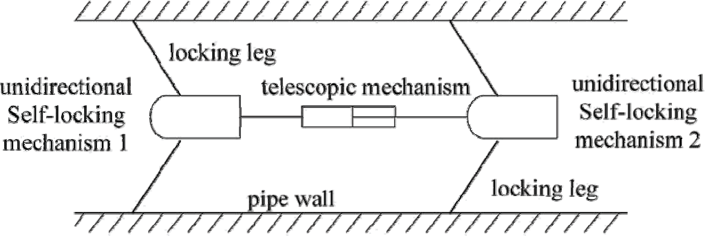
Figure 1 illustrates the propulsion principle of in-pipe robots based on a unidirectional self-locking mechanism. The robot is composed of two unidirectional self-locking mechanisms and a telescopic mechanism. The core function of the unidirectional self-locking mechanism is to lock the motion at one direction and keep it free to move at the other. For example, when the telescopic mechanism extends, unidirectional self-locking mechanism 1 receives a push force pointing to the left, and its locking legs receive friction forces pointing to the right from the pipe wall. Then the locking leg has the trend to rotate clockwise around the joint between the leg and the robot body, causing increasingly larger normal pressure and friction force between the leg and the pipe wall. Therefore, it is difficult for unidirectional self-locking mechanism 1 to move to the left and so self-locking can be realized. Contrarily, unidirectional self-locking mechanism 2 receives force to the right, and its locking legs have the trend to rotate counter clockwise, causing the normal pressure and friction between the locking legs and the pipe wall to become increasingly smaller. Therefore, unidirectional self-locking mechanism 2 can move to the right. On the other hand, when the telescopic mechanism shortens, similar steps take place, causing self-locking mechanism 2 to be locked to the left and mechanism 1 mobile to the right. In this way, the robot moves forward to the right. The unidirectional self-locking mechanism realizes self-locking by mechanisms, and the maximum tractive force is only determined by the telescopic mechanism's driving ability, not limited by the friction force between the robot and the pipe wall.
In-pipe robot's propulsion principle based on unidirectional self-locking mechanism
Locking Method Using Supporting Legs
This method realizes self-locking by pressing legs on the pipe wall, as shown in Figure 2. This structure is composed of supporting legs, supporting body and connecting mechanism. The supporting legs connect to the supporting body through revolute joints, about which torsional springs are used to overcome the weight of the legs and to preload the legs on the pipe wall. The prepressing force is very small and the leg's weight is very light, so they are neglected in the analysis. N and f are assumed as the sum of all normal pressures, the sum of all friction forces between all supporting legs and the pipe wall, respectively, and P is the sum of forces received along the direction of the legs, as shown in Figure 2 (b). F is the tractive force, and μ is the friction coefficient between the leg and the pipe wall. To realize self-locking, the following condition should be satisfied, i.e.,

Illustration of locking method using supporting legs. Pipe wall (1), elastic supporting legs (2), supporting body (3), connecting structure (4).

where

For the supporting legs, when the supporting bar stops rotating, the direction of the resultant force of N and f points along the bar through the centre of the revolute joint. If all forces balance, the following equation can be obtained:

For the supporting mechanism, along the telescopic direction, the following equation can be obtained:

By combining formulas (1) to (4), the condition of mechanism's self-locking is:

The structure of this self-locking mechanism is simple and easily realized. In addition, the whole size of the robot can be very small. However, two shortcomings exist in such a robot. The first is that, because the supporting legs always pre-press into the pipe wall, a relatively large friction is generated against the robot's movement, resulting in loss of energy as well as severe wear of the supporting legs, therefore shortening the life of the robot. The second one is that the motion of the robot that adopts this locking mechanism (as shown in Figure 1) is unidirectional.
There are two kinds of locking method using inclined plane [17, 19], which are shown in Figure 3. It mainly uses the principle of an inclined plane's self-locking to realize unidirectional locking. As shown in Figure 3 (a), if the supporting shaft receives pushing force to the left, this mechanism has the trend to move to the left, causing the locking wheels to roll up along the inclined plane of the conical body and increasing the normal pressure exerted on the inner wall by the locking wheels. So the mechanism is locked to the left. If the supporting shaft receives a push force to the right, the conical body will move to the right, and the locking wheels separate with the pipe wall and the mechanism can move to the right. The locking theory shown in Figure 3 (b) is similar to Figure 3 (a). Springs in both Figure 3 (a) and (b) are used to keep the locking wheels or wedges contacting the pipe's inner wall.
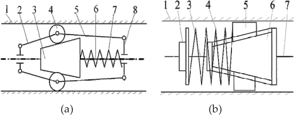
Illustration of locking method using inclined plane, (a) Inclined plane's locking method one: pipe wall (1), connecting bar (2), conical body (3), locking wheel (4), connecting bar (5), supporting shaft (6), spring (7), carriage (8). (b) Inclined plane's locking method two: pipe wall (1), hold-down nut (2), screw rod (3), spring (4), wedge (5), conical body (6), carriage (7).
The principle of the inclined plane locking method is diagrammed in Figure 4, in which f1 and f2 are the friction forces, N1 and N2 are the normal pressures exerted on the wheels by the conical body and the pipe wall, respectively, and F is the tractive force acted on the conical body.

Mechanical principle of locking method using inclined plane: (a) backward direction and (b) forward direction
When the conical body receives F pointing to the left, as shown in Figure 4 (a), with the resultant action of friction forces f1 and f2, the locking wheel receives a clockwise moment. Meanwhile, the normal pressures N1 and N2 are along the centre of the locking wheel, hence they do not produce any moment to the wheel. As a result, the wheel will rotate up along the inclined plane under the action of this moment, increasing the normal pressures N1 and N2, which will enhance f1 and f2. Finally, f2 is larger than F, realizing self-locking. When the conical body receives F pointing to the right, as shown in Figure 4 (b), similarly to above, the wheel will rotate down along the incline and the locking will be released, so the conical body can move to the right.
From the above analysis, the tractive force of the telescopic in-pipe robot based on this method can be increased as the rise of loads, resolving the contradiction between large tractive force and friction force. However, two shortcomings exist in such a kind of robot. The first is that the locking mechanism can realize self-locking in only one direction, and the second is that the adapted pipe diameter is limited by the length and taper of the conical body. If the robot is required to cross bent pipes, the conical body cannot be too long, and thus the adapted diameter range is usually not large. Therefore, it is significant to make an in-pipe robot with the capabilities of adapting to a wide range of pipe diameters and of moving bilaterally.
This method is based on the self-locking principle of a cam, as shown in Figure 5. The motor drives the lead screw to rotate, so the moving nut moves along the axis of the lead screw. Meanwhile, the nut drives the pushing bar, which pushes the parallel four bars to transform. Thus, the cams mounted on the horizontal bars press on or separate from the inner pipe wall, realizing locking or unlocking.
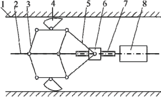
Illustration of locking method using cams: pipe wall (1), carriage (2), parallel four bars (3), cam (4), pushing bar (5), moving nut (6), lead screw (7), motor (8)
To simplify the analysis of the locking principle, we assume each bar's stiffness is large enough, and the four-bar mechanism is considered as a rigid body, as shown in Figure 6, f is the friction force exerted on the cam by the pipe wall, N is the normal pressure exerted on the cam by the wall and F is the tractive force acting on the mechanism.

Illustration of a cam's locking mechanical principle: (a) backward direction and (b) forward direction
When the mechanism receives a forward tractive force as shown in Figure 6 (a), the cam rotates anti-clockwise due to the friction force f. Accordingly, N is increased, as it the friction force f. In the end friction force f will be larger than F and self-locking can be realized.
When the mechanism receives a backward tractive force, as shown in Figure 6 (b), the cam rotates clockwise and N is decreased, reducing the friction force f. Therefore, the mechanism is unlocked in the backward direction.
Through the above analysis, a robot with such a locking mechanism has two advantages. First, the friction force exerted on cams will increase with the tractive force due to the cam's self-locking, so the robot has a relatively large tractive force. Second, because the transformation scale of the parallel four-bar mechanism is large, the robot can adapt a large change of the pipe's diameter scale. However, such a robot has two shortcomings: the cam's self-lock is unidirectional, making the robot able to move only in one direction; and there is a large load acting on the four bars. If the bar is thin and small, the threshold of the load taken by the bars is also small. Moreover, if the bar's dimension is small, it is not easy to install the cams. Therefore, the configuration of in-pipe robots that utilize this method is usually large.
The Principle of Bilaterally-Controllable Locking Mechanism
In this paper, a new bilaterally-controllable locking mechanism is proposed. The idea is to make use of the cam's self-locking theory in order to provide a relatively large tractive force for the in-pipe robot. As shown in Figure 7, the motor drives the screw rod, along whose shaft the nut moves. Thus the cams on one side are drawn back while those on the other side contact the pipe wall. The cams’ fold and unfold position can be controlled by changing the position of the nut, thus the switching of locking direction and moving direction can be achieved. This mechanism has the following features: (1) the tractive force is not limited by the maximum static friction force; (2) by controlling the locking direction, the robot can move in two directions; (3) by changing the contact points on the cam surface, different pipe diameters can be adapted; (4) by controlling the locking mechanism, both moving directions can be locked at the same time, which means the robot can be fixed at a certain position in the pipe, and this provides some advantage in fixed-point operations.

Illustration of a controllable locking mechanism: pipe wall (1), cam (2), moving nut (3), connecting bar (4), screw rod (5), motor (6), carriage (7)
Figure 8 shows the cam's self-locking mechanism, in which xoy is the fixed rectangular coordinate system, F is the tractive force exerted by the telescopic mechanism to the unidirectional locking mechanism, F1 is the component of F along the direction of OQ, point O is the centre of rotating shaft of the cam, point Q is the contact point between the cam and the pipe wall, N and f are normal pressure and friction force exerted on the cam at point Q by the pipe wall, respectively, θ is the angle between OQ and vertical direction, and F1x and F1y are the projections of F1 on axis x and y, respectively.

The cam's self-locking theory
To ensure the rationality of the following analysis, the cam's stiffness is assumed to be large enough so it will not be deformed under the action of F. Meanwhile, the friction coefficient between the cam and the pipe wall is μ. Thus the acting forces at point Q are as follows:

To avoid the relative slip between the cam and the pipe wall at point Q, the following condition must be satisfied:

Assume the tangent angle corresponding to μ is θ f and meets:

From equation (6), (7) and (8), the further condition that the cam can self-lock can be achieved:

A telescopic robot usually needs two bilaterally-controllable self-locking mechanisms, shown in Figure 7. A structure model was built for the bilaterally-controllable self-locking mechanism, as shown in Figure 9. In Figure 9, xoy is a fixed Cartesian coordinate system, l1 and l2 are the lengths of the two rods, ®1 and ®0 are the short diameter and the long diameter of the cam, α is the angle of the cam profile, β is the angle between the left cam and x axis when folding the left cam (unlock). θ is the angle between the right cam and x axis when unfolding the right cam (lock), and H1 and H0 are the distances between the moving nut and the two cam supporting points O and O1, respectively.

Analysis of the bilaterally-controllable self-locking mechanism
In order to ensure that the locking mechanism can change the moving direction, the following conditions must be satisfied. When the inchworm robot moves forward (to the right), the left cam can be folded to unlock, and, at the same time, the right cam can be unfolded to lock. When the inchworm robot moves backward (to the left), the left cam can be unfolded to lock, and the right cam can be folded to unlock.
In order to simplify the calculation and control strategy of the controllable locking mechanism, the nut is constrained to two position states. One position state is that the nut is at the right end of the screw, the locking mechanism is in the state shown in Figure 9. The left cam is pulled down by the connecting rods and rotates clockwise around joint O, entirely folded and having lost contact with the pipe wall. On the other hand, the right cam is entirely unfolded and is not constrained by the connecting rods, keeping contact with the pipe wall under the effect of a torsional spring. In this way, the whole mechanism is locked from moving to the left and is easily able to move to the right. Another position state is that the nut is at the left end of the screw, as shown in Figure 7. Accordingly, the moving direction of the robot switches to the left since the self-locking mechanism stops the motion to the right.
When the nut is at the right end of the screw, to ensure self-locking to the left, H1 and H0 must satisfy the following conditions:

In this design, the robot can adapt different pipe diameters by rotating the cam. In order to enlarge the adapting range of the pipe diameter, the cam must be able to rotate freely. Thus it is necessary to analyse the singular position of the cam mechanism. There are three possible singular positions, as shown in Figure 10. In Figure 10 (a), the two rods locate in line with point G point M and point K collinearly, where the cam cannot rotate anymore. Figure 10 (b) shows that the revolute joint M is on the line of OG. Since joint M cannot go through the cam, this configuration forbids the cam from rotating clockwise. When joint M is on the line of OK, as shown in Figure 10 (c), the cam is not allowed to rotate clockwise again, since joint M cannot pass through the lead screw. In Figure 10 (b) and (c), ø is the angle between the long edge of the cam and the axis perpendicular to the pipe axis. If ø > α, where α is the angle of the cam profile as shown in Figure 9, the two singular positions will not influence the expanding and locking of the cam.

Singular position of the cam mechanism: (a) singular position 1, (b) singular position 2, and (c) singular position 3
The kinematic scheme of the cam mechanism is built as shown in Figure 11, where xoy is the Cartesian coordinate system, α is the angle of the cam profile, point O, G, M, K are the four joints, β is the angle between the line OG and ox axis, and θ is the angle between the line OM and ox axis.
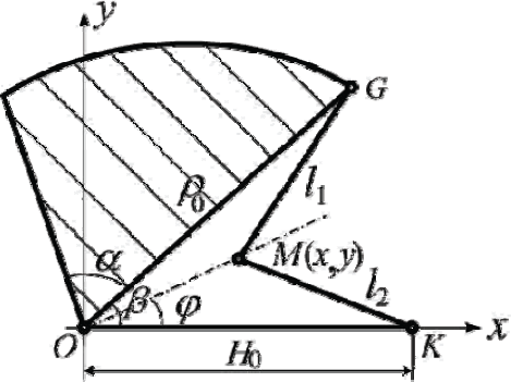
The kinematic scheme of the cam's four bar linkage mechanism
According to the above singular position analysis, in order to avoid the singular position when the highest point of the cam contacts the wall of the pipe (β = 90°), as shown in Figure 10 (a), the following condition must be satisfied:
The cam needs to rotate to adapt the changing diameter of the pipe. The constraint conditions of the joint M can be described as:

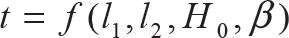
The following equations can be derived from Eq. (12).

Equation (13) can be further expressed as:

where
The following result can be obtained from Eq. (14).
Defining β ∊ [90° - α, 90°], according to the geometry, the line OM is in the angle between the line OG and the line OK, and the following equation should be satisfied:

According to the continuity of the linkage mechanism's movement, if the boundary condition meets Eq. (17), Eq. (17) can be further expressed as follows:

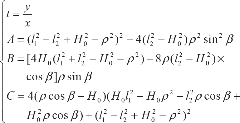
Given β = 90° – α, the following equation can be derived from Eq. (14) and (15).

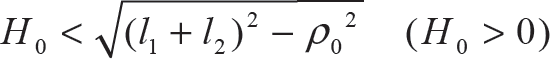
When β = 90° – α, inappropriate values of l1, l2 and H0 may lead to the result that B2 – 4AC < 0, resulting in no solution to Eq. (14). To solve this problem, the values of l1, l2 and H0 should satisfy the following condition:

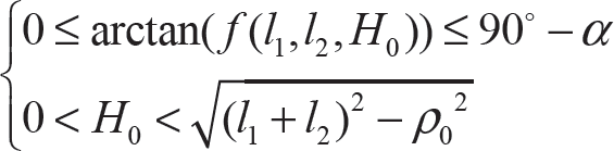
In order to get a large adapting range of the pipe diameter for a certain α, besides the condition of Eq. (20), the parameters l1, l2 and H0 should also satisfy the following condition:
The Prototype Development
The overall design of the locking mechanism is shown in Figures 12 and 13. Figure 12 shows the structure of the unidirectional locking mechanism, which is mainly composed of cam 1, torsional spring 2, shaft 3 and fixed mount 4. Three cams are located at the fixed mount circumferentially 120° apart from each other and connected by the shafts. The torsional spring is assembled on shaft 3, and the cam can always contact the pipe wall due to the tension of the torsional spring.

Unidirectional self-locking mechanism: cam (1), torsional spring (2), shaft (3), mount (4)
Figure 13 shows the structure of the direction-controllable self-locking supporting mechanism, which is mainly composed of the small-power DC motor 1, flexible shaft 2, universal joint 3, coupler 4 and the new locking mechanism. The new locking mechanism is composed of two unidirectional self-locking mechanisms. These two unidirectional self-locking mechanisms are connected together by the lead screw 9 and the nut 8. The connecting rod 7 combines the nut 8 and the cams, and the motor mount 1 and unidirectional self-locking mechanisms are connected by the universal joint 3. The motor shaft and the lead screw are connected together by the flexible shaft 2 and the motor coupler 4. In the design process of this direction-controllable self-locking mechanism, if the motor and this mechanism are connected directly, the robot will have a longer single segment, which requires a larger turning radius of the pipe. Consequently, the universal joint and flexible shaft are used in our design to decrease the turning radius of the robot.

Direction-controllable self-locking supporting mechanism: motor and its mount (1), flexible shaft (2), universal joint (3), coupler (4), mount (5), cam (6), connecting rod (7), moving nut (8), lead screw (9)
Motor 1 drives the lead screw 9 by the flexible shaft 2, then the lead screw 9 drives the moving nut 8 moving along the lead screw 9. When the locking mechanism is required to lock moving to the left, the nut moves to the right end, pulling the left connecting rod to draw back the left cam; meanwhile, the right connecting rod is slackened, so that the right cam can contact the pipe wall under the action of the torsional spring. The steps are similar for the mechanism locking to the right.
The inchworm in-pipe robot based on the new self-locking supporting mechanism is shown in Figure 14. It includes two supporting mechanisms at two ends and a telescopic driver in the middle. The supporting mechanism is the structure shown in Figure 13. The telescopic driver is composed of leading screw 10 and nut 2, leading screw's mount 3, flexible shaft 5, motor 6 and motor's mount 7. The leading screw's mount is connected with the motor's mount by universal joints 4, and the leading screw is connected with the motor shaft by flexible shaft 5. The moving nut 2 is connected with the supporting mechanism 1 by the universal joint 11. The motor's mount is connected with supporting mechanism 8 by another universal joint 9. The motor that drives the telescopic mechanism is a DC motor and its velocity is determined by the input voltage.

Structure of the inchworm in-pipe robot: self-locking supporting mechanism (1), moving nut (2), leading screw's mount (3), universal joint (4), flexible shaft (5), driving motor (6), driving motor's mount (7), self-locking supporting mechanism (8), universal joint-2 (9), leading screw (10), universal joint (11)
The prototype of the direction-controllable locking supporting mechanism is shown in Figure 15. The two working conditions, i.e., the locking mechanism locks moving to the left and the right, are shown in Figure 16.
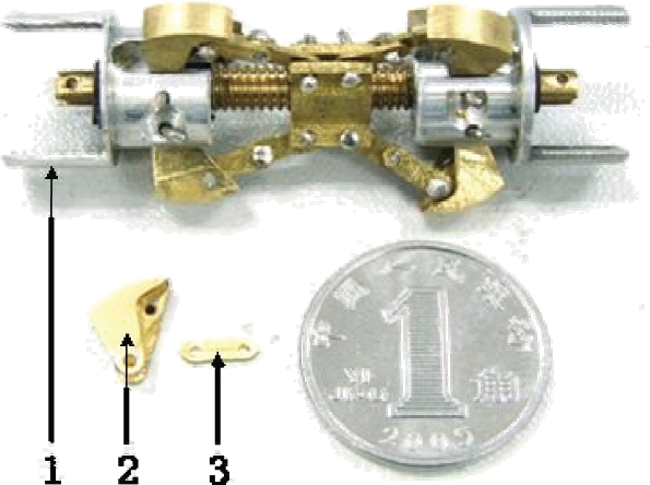
The prototype of the direction-controllable locking supporting mechanism: locking mechanism (1), cam (2), connecting bar (3)
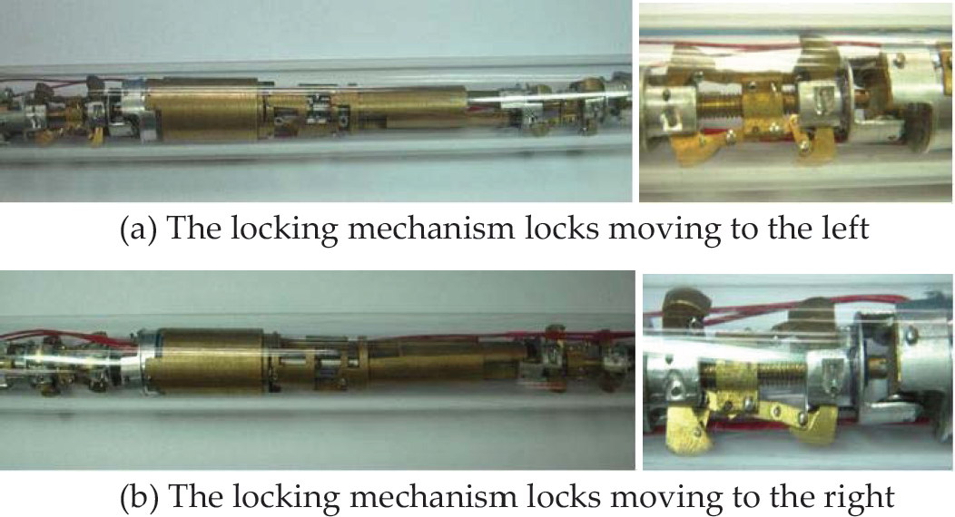
Two working conditions of the direction-controllable locking mechanism
Self-Locking Test and Direction-Controllable Locking Test
In order to verify the locking mechanism's self-locking and direction-controllable locking abilities, experimental tests were conducted. The test method is shown in Figure 17 (a) and the physical testing prototype is shown in Figure 17 (b). The test process was as follows. First, a line was connected to each end of the locking mechanism, and the other end of the line was connected to a spring balance. The lead screw was adjusted to cause the locking mechanism to lock moving to the left. Then the mechanism was placed in a pipe with an inner diameter of Φ18mm. After that, a pulling force to the right was exerted on the mechanism at its right end. As a result, the locking mechanism easily moved to the right. The right spring balance showed a very small pulling force, which conquered the friction force between the mechanism and the pipe wall. Then a pulling force to the left was applied at the left end of the mechanism. The force gradually increased up to 2.5kg and the mechanism was still locked at its position. A larger force was not tested for safety reasons. Similarly, the above test was repeated after the mechanism was switched to the other locking condition, and the mechanism was locked moving to the right. The same result was obtained for the pipes with inner diameters of Φ17 mm and Φ20 mm.

Locking mechanism tests
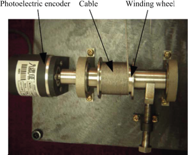
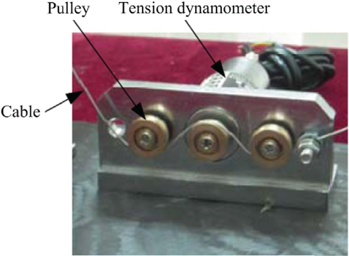
The direction-controllable locking mechanism was applied to develop a micro inchworm in-pipe robot, as shown in Figure 18. The tractive force of the robot was tested with the test method shown in Figure 19 and the corresponding test bed shown in Figure 20. A traction cable is connected to the end of the robot, and a load is applied on the traction cable by a load adjusting device. A tension sensor is placed between the robot and the load. The load adjusting device is shown in Figure 21. The screw is used to increase or decrease the pressure to adjust the friction between the winding reel and the friction pad. The contactor is connected to the screw by a spherical hinge. Through this device, continuous and variable loads can be produced to test the traction ability of the robot. The robot's velocity is measured by the velocity detecting device shown in Figure 22. When the robot moves and pulls the traction cable, the winding wheel rotates and the rotational speed is measured by the coaxially located photoelectric encoder. The rotation speed of the winding wheel can be converted into the robot's velocity by simple calculations. The tractive force is measured by the tension detecting device shown in Figure 23. The cable twined on the winding reel goes through the tension dynamometer in a zigzag way. When the robot moves, the cable will exert pressure on the middle pulley and compressive stress will occur. The tractive force of the robot can be obtained by the tension dynamometer measuring the compressive stress.

Inchworm in-pipe robot based on direction-controllable locking mechanism: motor for driving locking mechanism 1 (1), locking mechanism 1 (2), lead screw for driving robot (3), motor for driving robot (4), locking mechanism (5), motor for driving locking mechanism (6)

The test method of tractive force of the robot based on direction-controllable locking mechanism

The test bed of tractive force of the robot based on the direction-controllable locking mechanism: in-pipe robot (1), pipe (2), the slope adjusting device (3), protractor (4), wire (5), tension sensor (6), traction cable (7), wheels (8), encoder for speed (9), the load adjusting device (10)

The load adjusting device
The velocity detecting device
The tension detecting device
During the tests, all the motors are given maximum rated voltages to ensure maximum output powers. In the test of moving to the right, at first, the locking direction is set to the left by controlling the motors of the supporting mechanisms, in which the screw nut is driven to the right end. As the screw nut has a self-locking feature, it will stay.
At its position after the motor is power off. Then, the telescopic driving mechanism starts to work. Since the robot is locked moving to the left, the telescopic driving mechanism extends, to push the right supporting mechanism to the right, and shortens to pull the left supporting mechanism to the right. In this way, the robot can move to the right step-by-step using the input voltage shown in Figure 24.

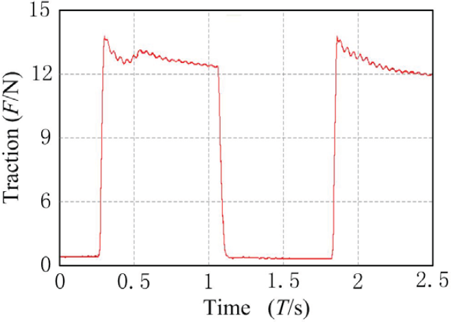
Input voltage of the motor when testing the traction
The robot motions are recorded under different loads. Figure 25 shows the maximum tractive force that the robot achieves when the velocity is 10mm/s, and Figure 26 plots the robot velocity under different loads. From Figure 26, the following results can be achieved: the maximum velocity of the robot is 10mm/s while the corresponding maximum tractive force is 12N; when the traction load is larger than 12N and further increases, the velocity decreases gradually. Besides, for different gradients of the climbing pipe, the results of the tractive force have slight differences because of the lightweight design of the robot. In the experiments, the pipe is filled with atmosphere and other filling materials such as water, oil, are not considered. In some cases, the pressure and the viscosity of the material could influence the performance of the robot.
Maximum traction when velocity is at its maximum

The tractive force versus velocity of the in-pipe robot based on the direction-controllable locking mechanism
The unidirectional locking mechanism is utilized in the telescopic in-pipe robot, which is not limited by the maximum static friction force between the robot and the pipe, thus making it possible to enlarge the tractive force. This design is very meaningful because the maximum static friction force is relatively small for the micro in-pipe robot.
Three types of unidirectional locking mechanism were analysed: the locking mechanisms that use supporting legs, inclined planes and cams. Based on the analysis, a new type of locking mechanism, which has a larger adapting range of pipe diameter and controllable locking direction, was proposed. It can address the problem of the traditional unidirectional locking mechanisms, which cannot move both forward and backward. Moreover, it enables the robot to fully lock at a certain place, making fixed-point operation in the pipe possible.
The locking conditions of the cam locking mechanism were presented, and a prototype of the new direction-controllable locking mechanism was developed. Tests showed this mechanism fitting a pipe with diameter of Φ18 mm had a tractive force up to 25N, and the adapting range of pipe diameter was Φ17~Φ20 mm. Furthermore, it was able to lock in both directions. These advantages can significantly improve the performance of the micro in-pipe robot in practical applications.
Large tractive force can be achieved by applying this kind of self-locking mechanism in the Inchworm micro in-pipe robot. Experimental results showed that our robot had a maximum tractive force of 12N when the maximum velocity of the robot was 10mm/s. The reason limiting the further increase of the tractive force lies only in the driving capability of the motor, instead of the friction force between the robot and the pipe wall.
This work was funded by a grant from the National High Technology Research and Development Program of China (863 Program) (No. 2007AA04Z256) and partly funded by the National Natural Science Foundation of China (51205400). This article is a revised and expanded version of the paper entitled “Development of Controllable Two-way Self-locking Mechanism for Micro In-Pipe Robot” presented at Intelligent Robotics and Applications, Third International Conference, ICIRA 2010, Shanghai, China, November 10–12, 2010.