
Abstract
In this study, the processing efficiency and cost of centrifugal 3-D impeller rough machining using five-axis flank milling, linear shaft linkage high-speed milling and fixed-axis plunge milling were assessed. Furthermore, the nylon material cutting test was carried out to verify the geometrical precision of the fixed-axis plunge milling toolpath planning method used for the centrifugal 3-D impeller. Meanwhile, an empirical model for estimating the cutting force in plunge milling was established via the orthogonal cutting test. This ensured the smooth operation of the subsequent fixed-axis plunge milling cutting test. Cutting parameter optimisation and tool strength verification were performed for the impeller inlet, which was narrow and deep. On this basis, cutting tests for three FV520B impeller passages were conducted using the above-mentioned three methods. The results revealed that fixed-axis plunge milling exhibited a relatively large advantage regarding processing efficiency and cost. Additionally, the advantages were more obvious when the fixed-axis plunge milling was performed with a large-sized cutter.
Keywords
Introduction
Centrifugal compressors are employed extensively in numerous fields such as metallurgy, petrochemical engineering, gas transportation and refrigeration. This is due to their simple structure, stable and reliable operation, high efficiency, high single-stage compression ratio and extensive working conditions. The centrifugal three-dimensional (3D) impeller is a core component of centrifugal compressors. Thanks to its high machining efficiency, it has garnered widespread attention from scholars worldwide. Approximately 60%–70% of materials should be removed during the rough machining of impellers. However, restricted by the difficult machining properties of certain materials, impeller machining enterprises frequently encounter low impeller channel efficiency during rough machining and subsequently delayed production cycles. The previously widespread five-axis linkage side milling method1–5 has been abandoned because of the low feed rate caused by the large cutting depth and the poor stability due to the large number of linkage shafts. Since these issues seriously affect the impeller-based production cycle, the linear axis linkage high-speed end milling method6,7 has become popular. In this method, the impeller channel is applied to the processing of various portions along the gas flow direction. Besides, each machining area is completed by three-axis linkage layered numerical control (NC) machining. The two rotating axes of the machine tool only play an adjustment role, improving stability to a certain extent. However, the influence of small axial cutting depths, cutter axis vector identification or machining area division is negligible, which partially limits further enhancements in machining efficiency.
In recent years, plunge milling has become widely applied in the rough machining of cavity parts owing to its high material removal rate. In contrast to conventional layered side milling and high-speed end milling, the cutter in plunge milling mainly bears an axial cutting force. Subsequently, cutter deformation is low due to the small radial force. However, the axial stiffness of the cutter is high and the stress condition of the cutter is strong, thereby facilitating the rough machining of complex parts such as impellers. Given the machining problems of integral bladed disks in aircraft engines, Hu et al.8–11 systematically explored the rough machining plunge milling of bladed disks. Ultimately, they proposed the five-coordinate and four-coordinate plunge milling method of bladed disk channels. Their approach involved approximating the ruled envelope surface to the equidistant surface of the bladed disk channels, which could be used as the boundary surface of the cutter axis during plunge milling in the rough machining of bladed disks. Li et al. 12 developed a rough algorithm for the plunge milling of integral bladed disks based on the least squares (LS) principle. Accordingly, the blade margin after plunge milling could be evenly distributed at the blade profile value points, which was conducive to subsequent blade machining. Liang et al. 13 calculated the tool orientation and locations in four-axis rough plunging of open blisks, so that the residual raw material left on the blades after roughing was close to the specified value. Sun et al. 14 proposed a new plunge milling tool path generation method using medial axis transform in which the radial depth could be easily controlled, so that the cutting efficiency and cutter life were improved. Dong et al. 15 created the cylindrical approximation method of the channel surface. Using this technique, the optimal cutter axis vector for the plunge milling of cavity parts was obtained. This approach has been applied to the plunge milling rough machining of centrifugal 3D impellers. Huang et al. 16 developed a new plunge milling toolpath generation method with adaptive intervals that restricted the maximum scallop height within a given value, thereby improving the machining stability and tool life. Dong et al. 17 established an in-process model of four-axis plunging that represented the geometry of the part in the process of plunging, so that the residual and overcut of the material could be evaluated. Huang et al. 18 investigated the influences of tool engagement angle and tool geometry on tool wear based on multiple sets of machining tests. The development of tool wear during plunge milling was also monitored, through which the optimal engagement angle could be achieved while considering both tool life and machining efficiency.
In summary, the rough machining methods of centrifugal 3D impellers primarily include five-axis side milling, linear axis linkage high-speed milling and plunge milling. Regarding five-axis side milling and linear axis linkage high-speed milling, several studies have carried out machining simulations or experimental cutting research.4–7 However, as for plunge milling, only machining simulations have been performed in one previous study. 15 As a result, the cutting efficiency of various methods in authentic machining processes cannot be compared. In this study, a centrifugal 3D impeller was selected as the experimental object. Five-axis side milling, linear axis linkage high-speed milling and plunge milling were applied to the rough machining of different channels on the centrifugal 3D impeller. On that basis, the machining efficiency and cost of these methods were evaluated.
Principle experiments for the fixed-axis and variable-axis plunge milling of impellers
The cutter-path planning method 15 has not yet been verified through cutting experiments. Therefore, it is necessary to perform trial cutting before the NC machining of integral impellers to avoid over-cutting or interference. The experiments in this section verified the geometric correctness of the segmentation method, the cutter axis direction determination method and the cutter centre position in fixed-axis plunge milling, which were proposed in a previous study. 15 Nylon materials are relatively easy to machine, so they were selected for trial cutting. The findings from these experiments lay a foundation for the genuine material cutting of impellers.
Preparation of blanks
A semi-open 3D impeller (diameter: 450 mm; blade number: 17; outlet height: 29.9 mm) was selected as the research object for this experiment. To reduce experimental costs, parts of impellers comprising three blades and two channels were selected as the machining objects. According to the size of the partial impellers, nylon bar blanks with a size of φ200 mm × 295 mm were chosen. First, the nylon bar blank was machined into a cuboid of 295 mm × 160 mm × 130 mm on a sawing machine. Then, the front part of the cuboid was machined according to the size shown in the blank drawing of Figure 1(a) using the three-axis machining centre. Subsequently, the impeller cover disk surface, leading edge upper-end surface, impeller outlet circular arc surface and some parts of the shaft hole were machined. Figure 1 displays the blank drawing, model and blank after machining.

Blank used for rough plunge milling with fixed rotating axes: (a) blank drawing, (b) model of the blank and (c) blank after machining.
Machining process of the impeller channels
The impeller channel was machined following these procedures: rough machining and semi-finish machining of the channels, finish machining of the blade leading edges, finish machining of the blades and finish machining of the hub surface. This experiment was conducted according to the procedures listed in Table 1. In procedures 5, 6 and 7, R5T3 represents a ball-end cone milling cutter with a ball-end radius of 5 mm and a half-cone angle of 3°. The experiment was carried out on a five-axis DMG MAHO DMU 70V machining centre (Figure 2).
Manufacturing operation and cutters.

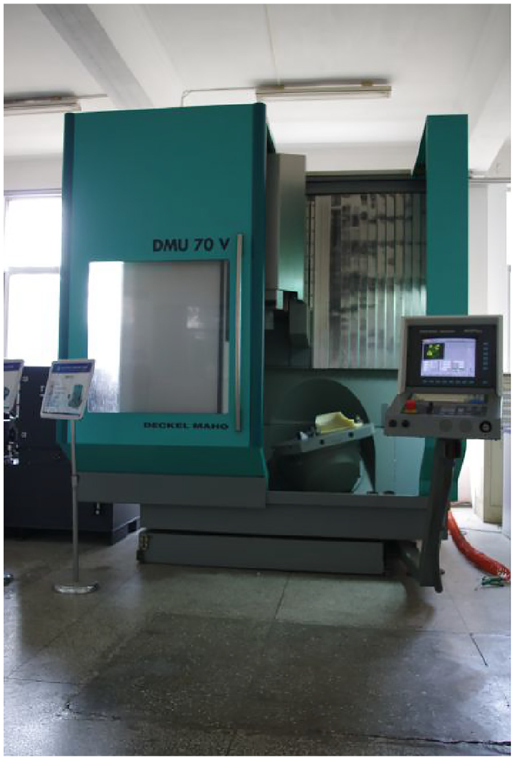
DMG MAHO DMU 70V five-axis machining centre.
Rough machining of impeller channels: Fixed-axis plunge milling
For the experimental object, an approach used in a previous study 15 was adopted to calculate the width of the channel on the hub surface (Figure 3). The impeller channel was evenly divided into three sections based on changes in its width (Figure 4). Subsequently, the triangular areas of the inlet and the outlet of the channel were combined with the first and third sections of the channel, respectively. Then, the segmentation parameters of the three sections of the channel on the baseline were obtained, namely, 0.0–0.3574, 0.3574–0.5958 and 0.5958–1.0.

Computation of the channel width.
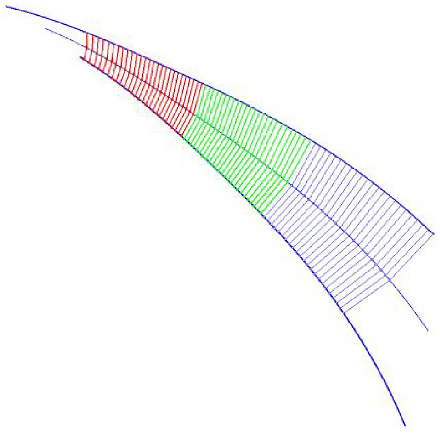
The tunnel was divided into three segments.
Based on the model of the previous study,
15
the maximum internal boundary of each channel segment (Figure 5), the optimal plunge milling direction and the parameter range of the four curves forming this segment were obtained. Specifically, the cutter axis vector corresponding to the first segment of the channel was
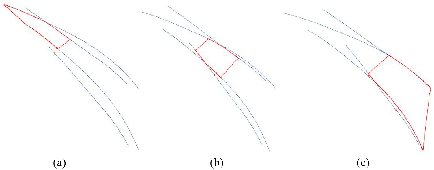
Maximum inscribed boundary curves of the three segments in the channel: (a) segment I, (b) segment II and (c) segment III.

Position of the plunge mill centre: (a) segment I, (b) segment II and (c) segment III.
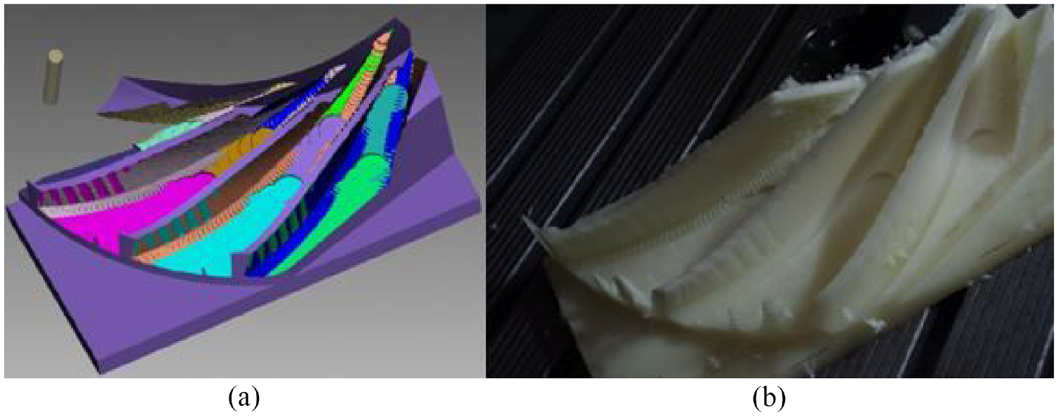
The cutter path mentioned previously was used for performing simulations and then cutting nylon materials. The simulation results for the rough machining of the impellers in each segment are shown in Figure 7(a), and the machining process photos of each segment are displayed in Figure 7(b) to (d).

Rough plunge milling with fixed rotating axes: (a) cutting simulation, (b) machining of inlet segment, (c) machining of middle segment and (d) machining of outlet segment.
Semi-finish machining of impeller channels: Variable axis plunge milling
In fixed-axis plunge milling, the rotary axis of the five-axis machining centre is fixed. If machining is performed on a machine tool with a ‘locking function’ in the rotary axis, the rigidity of the process system improves significantly, thereby enhancing cutting stability and machining efficiency in the rough machining of impellers. However, uneven machining allowance may occur after rough machining, which subsequently affects the finish machining of the impeller blades. Therefore, semi-finish machining was added between the rough machining and finish machining stages. The semi-finish machining step was realised through variable axis plunge milling. The cutter path and cutter axis direction in semi-finish machining were determined by slightly modifying the cutter-path planning method in the side milling of the ruled surface. This modification was performed in two steps. Firstly, the feed along the blade directrix direction was altered so that it was parallel to the cutter axis direction of each optimised cutter path during the side milling of the ruled surface. Following that, ‘finish machining allowance + cylindrical cutter radius’ was applied as the radius of the cylindrical cutter for calculations during cutter path planning. Considering the minimum distance at the inlet of the impeller channel and the free-cutting machinability of the nylon materials, a ϕ10 flat-bottom milling cutter was selected for the semi-finish machining of the impeller channels. Furthermore, the step spacing of the adjacent two cutter paths in plunge milling was set to 0.25 times the cutter diameter. The simulation results of the semi-finish machining are shown in Figure 8(a), while Figure 8(b) presents the actual machining results.
Semi-finish milling of the impeller: (a) cutting simulation and (b) actual machining.
Finish machining of the impeller channels
Finish machining of the impellers comprises three parts: blade leading edge finish machining, blade finish machining and hub finish machining. A ball-end conical cutter with a ball-end radius of 5 mm and a half-cone angle of 3° was employed in this process. Because machining of the blade leading edge, blade surface and hub surface was not the focus of this study, the cutter path used in the experiment was directly generated by NREC commercial software. Figure 9(a) displays the simulation results of the finish machining and Figure 9(b) presents the actual machining results. These figures reveal that the left channel was finished and the blade surface was continuous and smooth, without residual traces from rough machining or semi-finish machining.

Finish milling of the impeller: (a) cutting simulation and (b) actual machining.
Trial cutting of the nylon materials verified the geometrical correctness of the cutter-path planning method for the fixed-axis plunge milling of impeller channels proposed in a previous study. 15 This laid a foundation for the subsequent cutting experiments of the impeller material (FV520B).
Cutting force experiments and cutting parameter selection of fixed-axis plunge milling
The FV520B impeller material is a martensitic precipitation-strengthened stainless steel. This material undergoes three thermal treatment procedures (normalising, quenching and tempering), so it possesses outstanding comprehensive mechanical properties. For instance, the tensile strength (Rm) is 825 MPa, the yield strength (Rs) is 930 MPa, the elongation after fracture is 18.5%, the fracture shrinkage is 66% and the hardness is 311 HBW. To date, few studies have addressed plunge milling technology, and the selection of cutting parameters for the plunge milling of different workpiece materials with various cutter materials is not provided in the Machining Technologist’s Manual. 19 Meanwhile, considering the narrowness and depth of the impeller channel inlet and the small diameter and long overhang of the cutter, the strength of the cutter is crucial to completing the machining experiment. Therefore, it is necessary to verify the experimental parameters 20 in terms of the cutter strength. Limited by the minimum width at the impeller channel inlet, a two-tooth flat-bottomed integral cemented carbide milling cutter with a diameter of 10 mm manufactured by Fujigen Inc. (Japan) was selected as the plunge milling cutter. To verify the strength of the cutter in plunge milling, the cutting force that the tool could bear was determined. Since there is no empirical formula regarding plunge milling cutting force under corresponding conditions, an empirical formula for plunge milling cutting force at the impeller channel inlet was established through an orthogonal cutting force experiment.
Orthogonal plunge milling experiment
In plunge milling, cutting parameter selection exerts a significant impact on the cutting force, cutting temperature and other indexes.21–23 Of these variables, cutting force is the focus of this study. To explore how cutting force varied during plunge milling, an empirical model related to the cutting force was established. Based on an existing study,
24
an orthogonal experiment with three factors and four levels was designed for the plunge milling of FV520B. The three factors included milling linear speed
Cutting parameters and results of cutting force measuring.

The experiments were conducted on a CMV-850A three-axis machining centre manufactured by Dongtai Machine & Tool Co., Ltd. A total of 16 groups of experiments were carried out under the cooling of cutting fluid. The cutter used in the orthogonal cutting force experiment was the same as that used in the subsequent impeller machining, and the overhang length of the cutter was 70 mm. The 3D milling force was measured using a YDCB-11105 dynamometer, which was developed by the Institute of Sensing and Control, School of Mechanical Engineering, Dalian University of Technology, and manufactured by Yangzhou No. 2 Radio Factory, Jiangsu Province. The sampling frequency was set to 5120 Hz and the workpiece was aligned after being clamped onto the force-measuring platform. The force-measuring devices were connected in sequence, as Figure 10 indicates. The experimental site is presented in Figure 11.

Connecting schematic diagram of devices for cutting force measuring.
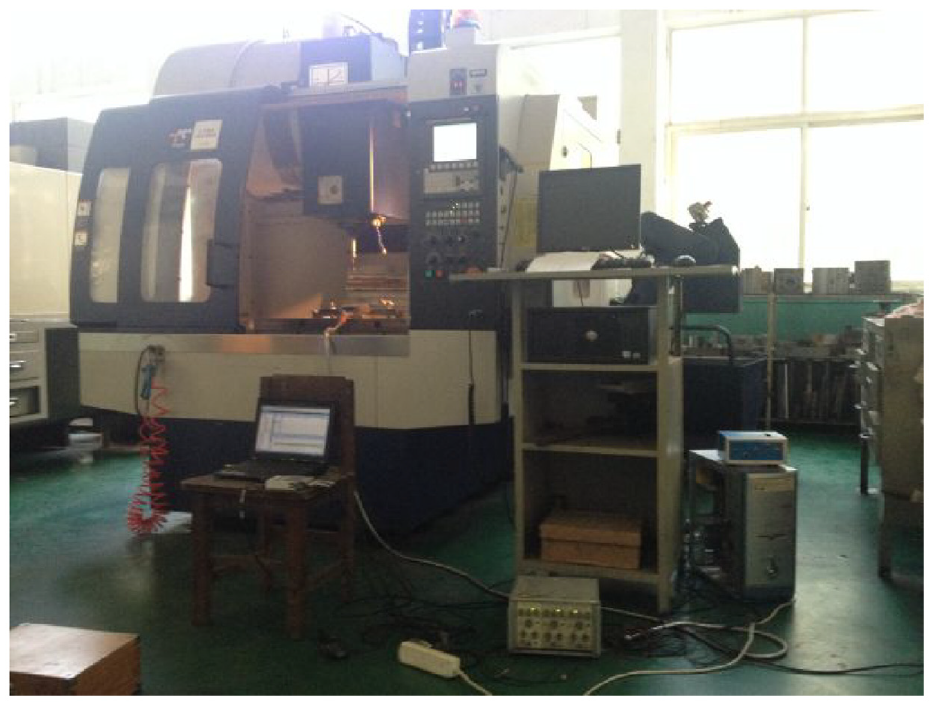
Testing site of milling force measurement.
Figure 12(a) illustrates the rotation direction of the cutter, the clamping position of the workpiece and the dynamometer, and the milling force direction. The plunge milling was performed according to the cutting position of the workpiece in the figure. As Figure 12(b) and (c) reveal, each cutting edge was cut from point A to point C in one rotation period of the cutter. According to the force direction shown in Figure 12(a), the workpiece was subjected to a negative force on the X-axis and a positive force on the Y-axis during the cutting process of the cutting edge from point A to point B, as Figure 12(b) indicates. Subsequently, the workpiece was subjected to a negative force in both the X-axis and the Y-axis during the cutting edge cutting process from point B to point C, as Figure 12(c) shows. Since the cutter was always fed in the positive direction on the Z-axis, the workpiece was always subjected to a positive force on the Z-axis. Figure 13 displays the cutting force collection results of the first group experiment.

Clamping position of the workpiece and directional specification of the cutting force: (a) experimental equipment and (b, c) directional specification of cutting force.

Sampling results of the cutting forces.
When the cutting state was stable, the average 3D cutting force peak value from five consecutive cutter rotation periods in the data collection curve was taken as the force value in this direction. Subsequently, the corresponding resultant force was calculated. The results of the 3D cutting forces and the corresponding resultant forces in the 16 groups of experiments are listed in Table 2.
Empirical model of the cutting force in plunge milling
According to a previous study,
19
the 3D cutting force can be expressed by an exponential formula that incorporates linear cutting speed

where
By utilising SPSS statistical analysis software, the experimental results of the force measurements in Table 2 were fitted using the multiple linear regression method. 25 The formula for the multiple linear regression can be expressed as:

Identification of cutting parameters and verification of cutter strength calculations
Based on the 16 groups of resultant forces from the orthogonal experiments in Table 2, the influence of the cutting parameters on cutting force was analysed using the visual analysis method,
26
also known as the range analysis method. Figure 14 illustrates the range analysis effect curve of the cutting resultant force. Generally, the cutting force falls as the linear cutting speed increases, and the cutting force reaches a minimum when the linear cutting speed reaches 50 m/min. Thus, the linear cutting speed was set at 50 m/min for the rough machining (plunge milling) of the impeller inlet section. Meanwhile, the cutting force rises when the feed per tooth and the radial cutting thickness increase. The radial cutting thickness exerts the most significant influence, followed by the feed per tooth. Since the linear cutting speed was set to 50 m/min and the radial cutting depth was identified as 2.5 mm, the feed per tooth was temporarily set to the upper limit of the experimental range, 0.02 mm/z. Verification of the cutter strength was performed through calculations using the parameter combination

Dose-effect curves of cutting forces using the R/S method.
In the machining process, the cutter can be regarded as a cantilever beam, which is subject to radial force, axial force and torque during cutting. The radial force

Deformation of the plunge milling cutter.
Equation (3) can be used to calculate the bending and deformation level
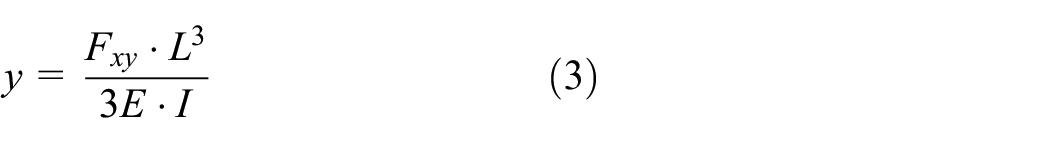
For the rough machining of the inlet section, a cemented carbide milling cutter with a YT15 grade was selected. The cutter had an elastic modulus (E) of 530 GPa, a bending strength (
Comparative experimental study on the rough machining of impeller channels
Compared with the conventional rough machining method of five-axis side milling, fixed-axis plunge milling has a larger axial force and smaller radial force on the cutter. As a result, this method is suitable for the machining of deep and narrow channels. To verify the effect of fixed-axis plunge milling in the cutting of real impeller materials (FV520B), a comparative study was performed regarding the machining efficiency and cost of fixed-axis plunge milling, linear axis linkage high-speed milling and five-axis side milling.
Impeller rough machining using the fixed-axis plunge milling method
The impeller cutting experiment with the FV520B material was performed using rough machining, semi-finish machining and finish machining cutter paths in the trial cutting of nylon materials. The test was conducted with a DMG DMU125P five-axis NC machine tool (Figure 16).

DMG DMU125P five-axis machining centre.
Rough machining of the impeller channel outlet segment
For these experiments, a cemented carbide powder-coated blade (model: XOMX120408TR-ME08/F40M) 29 was selected because cemented carbide powder-coated tools provide excellent machinability performance in terms of reduced cutting force, enhanced machined surface morphology and surface finish, and lower cutting temperature. 30 And an R217.79-2025.0-XO12-2AN two-tooth plunge milling cutter bar with a diameter of 25 mm (SECO, Sweden) was used as the cutter (Figure 17). The cutter path that was adopted was the same as in the trial cutting of the nylon materials. The radial cutting depth was 0.25 times the tool diameter, which was 6.25 mm. As recommended by the cutter manufacturer, the linear cutting speed ranged from 80 to 110 m/min. Also, the rotation speed of the main shaft was set to 1200 rpm, which was equal to a linear cutting speed of 94.2 m/min. According to the Machining Technologist’s Manual, 19 the feed speed was set to 312 mm/min (feed per tooth = 0.13 mm/z), and the machining time was 12 min. The impeller after machining is displayed in Figure 18.

SECO Φ25 plunge milling cutter.

Impeller outlet after fixed axes plunge milling
Rough machining of the impeller channel middle segment
In this set of tests, a cemented carbide powder-coated blade (model: XXMU10H308PR-MJAH140) was chosen. 31 As shown in Figure 19, an EVX10020RL two-tooth plunge milling cutter bar with a diameter of 20 mm (Tungaloy, Japan) was used as the cutter. Additionally, the cutter path used in the trial cutting of the nylon materials was employed. The radial cutting depth was 5 mm, which was 0.25 times the tool diameter. The linear cutting speed ranged from 80 to 120 m/min and the rotation speed of the main shaft was set to 1400 rpm (linear cutting speed = 88 m/min), as per the cutter manufacturer’s guidelines. Following the Machining Technologist’s Manual, 19 the feed speed was set at 220 mm/min (feed per tooth = 0.079 mm/z), and the machining time was 9 min. Figure 20 presents an image of the impeller after machining.

Tungaloy Φ20 flat-end milling cutter.

Impeller midpiece after fixed axes plunge milling.
Rough machining of the impeller channel inlet section
A φ10 two-tooth flat-bottomed milling cutter (Fujigen, Japan) was selected as the cutter for these experiments (Figure 21). Besides, the cutting parameters applied in Section ‘Identification of cutting parameters and verification of cutter strength calculations’ were adopted for machining. The rotation speed was 1600 rpm (linear cutting speed = 50 m/min), the feed rate was 64 mm/min (feed per tooth = 0.02 mm/z), the radial cutting thickness was 2.5 mm and the machining time was 39 min. A depiction of the impeller after rough machining is displayed in Figure 22.

FUJIGEN Φ10 flat-end milling cutter.

Impeller inlet after fixed axes plunge milling
Semi-finish machining of the blade and finish machining of the impeller
After rough machining, it is necessary to perform semi-finish machining of the blade and finish machining of the leading edge, blade and hub. Variable axis plunge milling is generally employed for semi-finish machining and can be completed in two phases. For the first segment of the channel, a φ10 two-tooth flat-bottom milling cutter (Fujigen, Japan) was selected. In contrast, a cemented carbide powder-coated blade with a 20-mm diameter EVX10020RL two-tooth plunge milling cutter bar (Tungaloy, Japan) was used as the cutter of the second channel segment. Figure 22 describes the impeller after semi-finish machining. For the finish machining of the leading edge, blade and hub, a ball-end conical milling cutter with a ball-end radius of 5 mm and a half-cone angle of 3° (Changshu Cutter Factory; Figure 23) was employed. An image of the impeller after finish machining is presented in Figure 24.

R5T3 ball-end cone milling cutter.
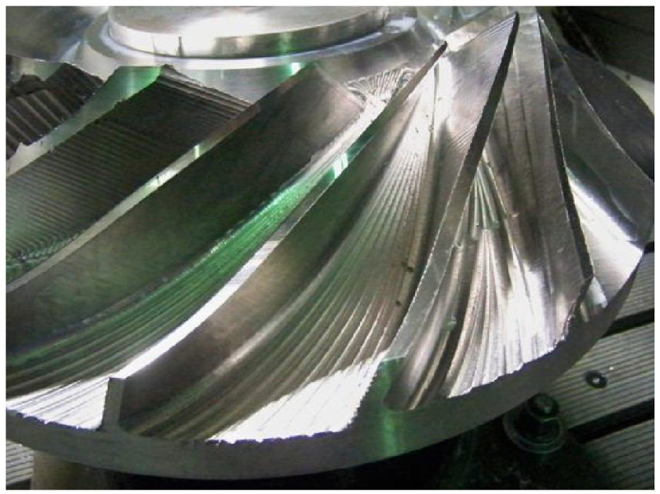
Finished impeller tunnel.
To draw a comparison between the plunge milling, linear axis linkage high-speed end milling and five-axis side milling methods, the cutting parameters, cutter diameter, cutting time and other relevant information for each machining procedure are listed in Table 3. Here, the material removal volume represents the volume of all the material removed from the workpiece in the corresponding operation, while the material removal rate signifies the volume of material removed from the workpiece in 1 min.
Machining information of fixed axes plunge milling.

Rough machining with the linear axis linkage high-speed end milling method
According to previous reports and the geometric characteristics of the impeller, each channel can be divided into three regions during impeller rough machining using the high-speed end milling method. Moreover, the cutter axis vector was not optimised, and it remained unchanged during the machining process in each region. Also, hyperMILL commercial software was used for NC programming. The cutter information, cutting parameters and machining time used for each machining region are presented in Table 4. Besides, the cutters are displayed in Figure 25 and the machining process is shown in Figure 26.
Machining information of linear shaft linkage high-speed milling.


Milling cutters for high-speed milling: (a) Stellramϕ25 round nose milling cutter, (b) Tungaloy Φ20 flat-end milling cutter and (c) FUJIGEN Φ10 flat-end milling.

High-speed milling processes of the impeller tunnel: (a) after milling of the outlet segment, (b) after milling of the middle segment and (c) after milling of the inlet segment.
Rough machining with the five-axis side milling method
Five-axis side milling is a conventional impeller machining method. Generally, a ball-end milling cutter is used to perform layered side milling of the channels. Owing to the geometric characteristics of the impeller, the channel can be machined in three layers from the shroud to the hub. A small feed rate and large cutting depth were adopted during machining, and the cutting depth was generally 70%–80% of the cutter diameter. NREC software was used for NC programming, and the cutting parameters were selected according to the Machining Technologist’s Manual. 14 The cutter information, cutting parameters and machining time in each machining program are listed in Table 5. Additionally, Figure 27 illustrates the cutters and Figure 28 depicts the machining process.
Machining information of five-axis side milling.


Milling cutters for five-axis layered flank milling: (a) R10T2 carbide ball end milling cutter, (b) R8T3 HSS ball end milling cutter and (c) R6T3 HSS ball end milling cutter.

Five-axis layered flank milling of the impeller tunnel: (a) after milling of the upper layer, (b) after milling of the middle layer and (c) after milling of the nether layer.
Cutting efficiency analysis
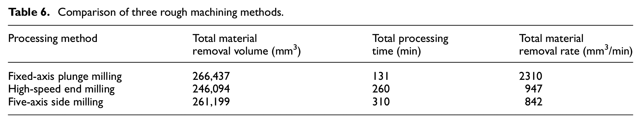
The total material removal volume, total machining time and total material removal rate of the three rough machining methods were compared, and the results are shown in Table 6. It was ascertained that the machining efficiency of conventional five-axis side milling was lower than that of fixed-axis plunge milling and linear axis linkage high-speed milling. Due to the large cutting depth and five-axis linkage, the feed speed was significantly limited. Besides, the cutter wear was fast and the cutters had to be replaced frequently during machining. This further reduced machining efficiency and incurred higher machining costs. As a result, this method is rarely used by impeller machining enterprises. Cutter-path planning is complicated to conduct in fixed-axis plunge milling since the automatic segmentation of impeller channels and the identification of the best cutter axis direction cannot be achieved through commercially available software. Furthermore, the residual allowance after machining is uneven, and semi-finish machining is still required. In this study, variable axis plunge milling was applied to the semi-finish machining of the blade. After semi-finish machining, the material removal volume of variable-axis plunge milling was higher than that of both linear-axis linkage high-speed milling and five-axis side milling. Additionally, this method simplified the finish machining of the blade and was at least twice as efficient as the other two methods. Regarding the rough machining of the channel outlet segment, the adoption of a cutter with a 25 mm diameter led to a material removal rate for fixed-axis plunge milling of 10,832 mm3/min. The material removal rate for linear axis linkage high-speed milling was only 1998 mm3/min, meaning that the machining efficiency was more than five times better. In the middle segment of the channel, the material removal rate for fixed-axis plunge milling and linear-axis linkage high-speed milling was 6894 and 789 mm3/min, respectively. This equated to a machining efficiency increase by a factor of almost nine. As for the inlet segment of the channel, the material removal rate for fixed-axis plunge milling and linear-axis linkage high-speed milling was 894 and 309 mm3/min, respectively. This reflected an increase in machining efficiency of a little less than three times. Therefore, fixed-axis plunge milling was considerably superior to linear-axis linkage high-speed milling. More specifically, fixed-axis plunge milling with large-size cutters exhibited especially obvious advantages. Thus, in the rough machining of large-sized impellers, the fixed-axis plunge milling method is the most preferable.
Comparison of three rough machining methods.
Comparison of machining costs
For the benefit of impeller manufacturers, the production costs were also evaluated. In the cutting experiment, the overall cost mainly includes machine tool operating costs and cutters/blades costs. Specifically, the machine tool operating cost was $42.86/h, while the machining costs of the individual machining methods are listed in Table 7. In the table, ‘Number’ denotes the number of cutters/blades consumed in the corresponding operation, ‘Unit price’ is the price per cutter/blade, ‘Machine hour’ represents the processing time of the corresponding operation and ‘Cost’ is the summation of the machine tool operating costs and cutter/blade costs.
Detail of processing costs.

The overall cost of the five-axis side milling method was $415.73. It exhibited no advantage over the other two methods due to its low efficiency and high cost. Compared to the high-speed milling method, the fixed-axis plunge milling method had a slightly higher cutter cost ($121.45 vs $116.01). However, the machining time was significantly lower (2.2 h vs 4.3 h), due to the higher machining efficiency. Of the three methods, the fixed-axis plunge milling method possessed the highest machining efficiency and the lowest production cost. In the experiment, only one channel was machined for each method, so the fixed-axis plunge milling method may present even more significant advantages in the rough machining of the entire impeller.
Conclusion
The cutter-path planning method of fixed-axis plunge milling described in a previous study 15 was applied to the trial cutting of nylon materials, and the geometric correctness of the cutter paths was verified. On that basis, rough and finish machining experiments of FV520B stainless steel were conducted. The fixed-axis plunge milling rough machining method was compared with the conventional five-axis side milling method and the linear axis linkage high-speed milling method. In the comparison experiments, to ensure the operational safety of fixed-axis plunge milling for the impeller channel inlet segment, which was narrow and deep, an empirical formula was established using cutting force-related orthogonal experiments to identify the cutting parameters and guarantee cutter strength during processing. Thanks to the above preparations, the experiment proceeded smoothly and the experimental results indicated that fixed-axis plunge milling exhibited significant advantages regarding machining efficiency and costs. Furthermore, fixed-axis plunge milling with large-size cutters demonstrated particularly obvious benefits.
Footnotes
Handling Editor: Sharmili Pandian
Author contributions
Improve processing efficiency and machining precision of centrifugal 3D impeller.
Declaration of conflicting interests
The author(s) declared no potential conflicts of interest with respect to the research, authorship, and/or publication of this article.
Funding
The author(s) disclosed receipt of the following financial support for the research, authorship, and/or publication of this article: This work was supported by Natural Science Foundation of Shanghai, and the Award Number is 15ZR1417200.
Consent to participate
Yes.
Consent for publication
Yes.