
Abstract
Face gear transmission is the transmission mechanism composed of cylindrical gear and face gear. At present, the tooth making method of face gear is still tooth cutting, with low material utilization and low production efficiency. The metal streamlines are cut off, resulting in low fatigue strength of gear teeth. In this paper, the forming of hot rolling was numerically simulated, with which the characteristics of equivalent stress field, equivalent strain field, rolling force variation, and metal flow in the process of rolling were analyzed. Finally, a hot rolling experimental device was set up, by which the face gear test piece was rolled. Then its tooth surface precision was investigated. The research reveals that hot rolling spur face gears is technological feasible and has promising prospects in industrial applications.
Introduction
Face gear transmission is a transmission mechanism composed by meshing of cylindrical gear and face gear, which is used to transmit the motion and power between intersecting shafts or staggered shafts. Face gear transmission has incomparable advantages in the field of aerospace because of its small volume, large reduction ratio, light weight, and low vibration and noise. 1 At present, face gears are commonly formed by cutting, which has low efficiency and high production cost. Tooth cutting can ruin the streamlines inside the metal material and reduce the bending strength of the tooth root. 2 In recent years, delightful progresses have been achieved in near net shaping machining of spiral bevel gears, so as to solve the problem of low material utilization by forming uniform and dense structures on the surfaces of gear teeth.3,4 The tooth surface shapes of face gears are special, and the use of precision forging has the defect of lower mold service life. 5 As an efficient manufacturing technology, hot rolling can improve production efficiency and reduce its cost.
Neugebauer et al. 6 established the gear rolling model and improved the gear bearing capacity. Takemasu et al. 7 proved that rolled gear tooth surfaces had relatively higher strength. Kamounchcong8,9 analyzed and studied the feasibility of cylindrical gear rolling based on the rolling principles. Khodaee and Melander 10 proposed that during the process of cylindrical gear rolling, the mold gear rotating and feeding speed would directly affect the resulted tooth profile. Sasaki et al. 11 achieved the tooth profile accuracy of DIN5 by shaping the tool gear and rolling the powder metallurgy helical cylindrical gear. Fu 12 revealed the influence mechanism of technical parameters on the changes of metal internal structure in rolling large module cylindrical gear by studying the changing processes of the microstructure during near net shape forming. Zhu et al. 13 studied the hot rolling of large module gears, established the microstructure evolution model, and analyzed the variation law of rolling forces. Qiao et al. 14 applied DEFORM-3D to reveal the flowing law of metal materials in rolling. Zhao 15 studied the forming mechanism of axial rolling for spur gear, and analyzed the principle of electromagnetic induction heating, as well as, the technology and forming mechanism of gear axial rolling in details. Ma 16 proposed a new technique of forced tooth splitting axial rolling, and studied the gear generating principle, free tooth splitting error, material flow mechanism, workpiece tooth length and height, rolling gear design method, experimental machine tool development, and workpiece accuracy. Zhang 17 researched the rolling life of gear mold, expounded the main processes and mechanism of fatigue failure, and the methods of quantitative calculation of fatigue life and analysis of crack propagation. Wang 18 studied the material fluidity in the process of gear axial rolling, and analyzed the stress of gear blank in the forming process by investigating the rolling forming simulation parameters and blank diameter. Zhang 19 carried out numerical simulation analysis on the rolling forming of straight bevel gear, analyzed the forming process of the lugs on the left and right sides of the tooth profile during the rolling process of bevel gear, and put forward the forming mechanism of lug defects. Jin et al. 20 studied the surface residual stress of hot-rolled aviation face gear. Zhang et al. 21 carried out the forming defects analysis for hot rolling hypoid gear. Wang et al. 22 studied the axial warm rolling process of the spur gear after heating. The researches on gear rolling technologies worldwide mainly focus on the cold rolling of small module cylindrical gears and the hot rolling forming of medium module cylindrical gears, which focus on the rolling forming technologies of face gears would hardly be found. In order to promote the industrial application of face gears, it seems necessary to carry on the research of their rolling forming technologies.
Numerical simulation of face gear hot rolling
Establishment of the coordinate systems for face gear machining and the cutter tooth surface equations
Establishment of gear tooth surface equation
The machining of face gears can be modeled after the machining method of cylindrical gears, based on the principle of generation. Cutting tools with the same or similar parameters as the cylindrical gears meshing with face gears are used for machining, as shown in Figure 1. The surface gear is machined, according to the principle of generative machining. Given the transmission ratio, the involute cutter tooth surface rotates relative to the machined face gear at the fixed rolling ratio, and the cutter envelope surface of the slotting cutter machines the tooth surface of the face gear. Therefore, the tooth surface equation of the face gear is derived from the tooth surface equation of the gear shaping cutter based on the meshing principle.

Schematic diagram of surface gear machining.
Based on the schematic diagram of face gear machining, with the tool rotation axis as the coordinate axis

Surface gear machining coordinate system.
From Figure 2, the transformation matrix between different coordinate systems can be calculated, and the transformation matrix

Figure 3 represents the tooth surface coordinate system of involute cutter, which corresponds to the face gear machining coordinate system in Figure 2.

Cutter involute coordinate system.
From Figure 3, the vector equation


In the formula,
Establishing the meshing equation
Assume the point is a point in the meshing area between cylindrical gears and face gears.

Therefore, the velocity vector

Similarly, in the face gear motion coordinate system

The velocity vector

Use

Where:

Convert the angular velocity vector

Use

Based on the gear meshing principle, the proper meshing conditions between the cutter tooth surface and the face gear tooth surface are obtained as follows:

Substitute (2-7) and (2-15) into (2-16) which is the proper meshing condition, the followings can be obtained:

where
Establishment of tooth surface equation for the face gear
The tooth surface vector

From (2-17):
Substitute (2–17) to (2–18) to calculate the tooth surface equation.
The rolling technology of face gear researched in this paper took the basic parameters of spur gear and its meshing cylindrical gear shown in Table 1 as an example. The three-dimensional model of spur gear blank was established with UG and saved as STL file. Figure 4 is a three-dimensional modeling diagram of the face gear.
Geometric parameters of spur gear and cutter.


Diagram of gears.
Setting of boundary conditions
The three-dimensional modeling STL file was imported into DEFORM-3D software to establish the numerical simulation model of hot rolling. To establish the rolling model of spur gear in DEFORM-3D, many factors needed to be considered, such as the preheating temperature of gear blank, the limitation of model boundary conditions and the non-linearity of material properties in the rolling process. In order to simplify the calculation, in the meantime, ensuring that the simulated rolling face gear was close to the actual working condition, the finite element simulation of hot rolling spur gear was simplified as followings:
In the rolling process, the elastic deformation of the mold gear and the gear blank is tiny, which could be ignored. The material for the gear blank was set as rigid plastic, 20CrMnTi, and the mold gear was set as rigid. The rolling temperature was set to 900°C.
The grid number of gear blank was set to 150,000. The grid was divided automatically, and the local grid refinement ratio was 0.01.
In the simulated rolling process of spur gear, the simulating model was set as the heat transferring type. The ambient temperature was set to 25°C, which was the same as the initial temperature as the mold. The contacting heat coefficient was set to 5 n/s/mm/C, the convection coefficient was 0.02 n/s/mm/C, and thermal radiance was 0.7.
Rolling motion description and parameter settings
The schematic diagram of the rolling forming motion for the face gear is shown in Figure 5. After the tooth blank was heated to 850°C–950°C through online intermediate frequency heating, the tool gear and the face gear were forced to mesh under the drive of the servo motor, and the tooth profile of the rolling face gear was fed axially along its axis under the force of the upper hydraulic cylinder. The lower face gear meshed with the tool gear to balance the axial force of rolling. In the rolling simulation, the cylindrical gear needed to be fed along the axial direction of the spur tooth face gear while rotating. The gear blank experienced plastic deformation under the compression of the cylindrical gear, and the protruding part conducted generative motion with the teeth of the cylindrical gear to generate the tooth profile of the face gear.
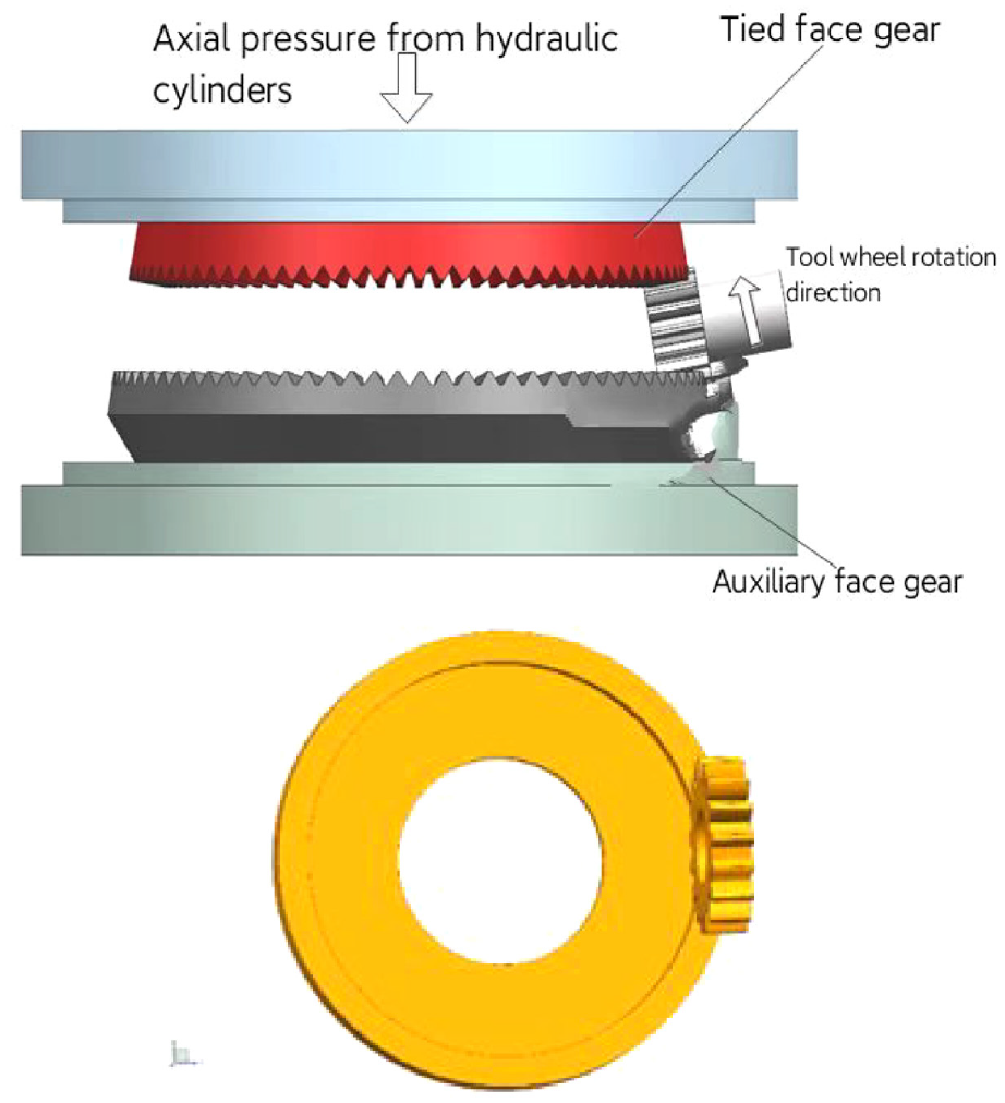
Schematic diagram of face gear rolling forming motion.
The rotating velocity of the mold gear was set to 30r/min and that of the face gear blank was set to 8.8 r/min. The feeding speed of the mold gear was set to 0.1 mm/s.
Numerical simulation analysis of the spur surface gear
The hot rolling forming analysis of the face gear
The deformations of the gear blank with different feeding depths of the mold gear were presented in Figure 6. The mold gear got in touch with the gear blank and formed a uniform tooth grooves on the surface, as shown in Figure 6(a). With the continuous increase of the feeding depth, the metal flow ranges were expanding, which spread from the gear blank surface to its bottom. And the tooth grooves were deepening, in the meantime, the tooth heights were increasing, as shown in Figure 6(b). When the mold gear was fed to the target depth, the complete tooth profile was rolled, as shown in Figure 6(c) and (d).

Rolling forming diagram of the face gear: (a) feed 20%, (b) feed 60%, (c) feed 100%, and (d) complete tooth profile.
Analysis of equivalent stress field of hot rolling face gear
According to the gear tooth forming process, the rolling process can be divided into initial stage, gear tooth forming stage, and gear tooth finishing forming stage. Figure 7 shows the equivalent stress diagram of hot rolled surface gear. When it was in the initial forming stage, from Figure 7(a), it could be seen that at this time, the mold gear was in contact and engaged with the gear blank, whose tooth top squeezed the tooth grooves of the gear blank. Therefore, the equivalent stress at the tooth grooves of the gear blank was relatively large, which was less in other areas. The maximum stress was 197 MPa near the root. In the gear tooth forming stage, it can be seen from Figure 7(b) that the equivalent stress near the contact areas between the mold gear and the gear blank was 262 MPa, and the stress areas also expanded significantly. When the feeding rate reached 100%, presented by Figure 7(c), the equivalent stress of the gear blank reached the maximum value of 411 MPa. Since the mold gear had been fed to the full tooth depth, only part of the top area of the mold gear teeth was in contact with the tooth root of the gear blank. In the following finishing stage, the feed rate remained unchanged, while the equivalent force was decreased.
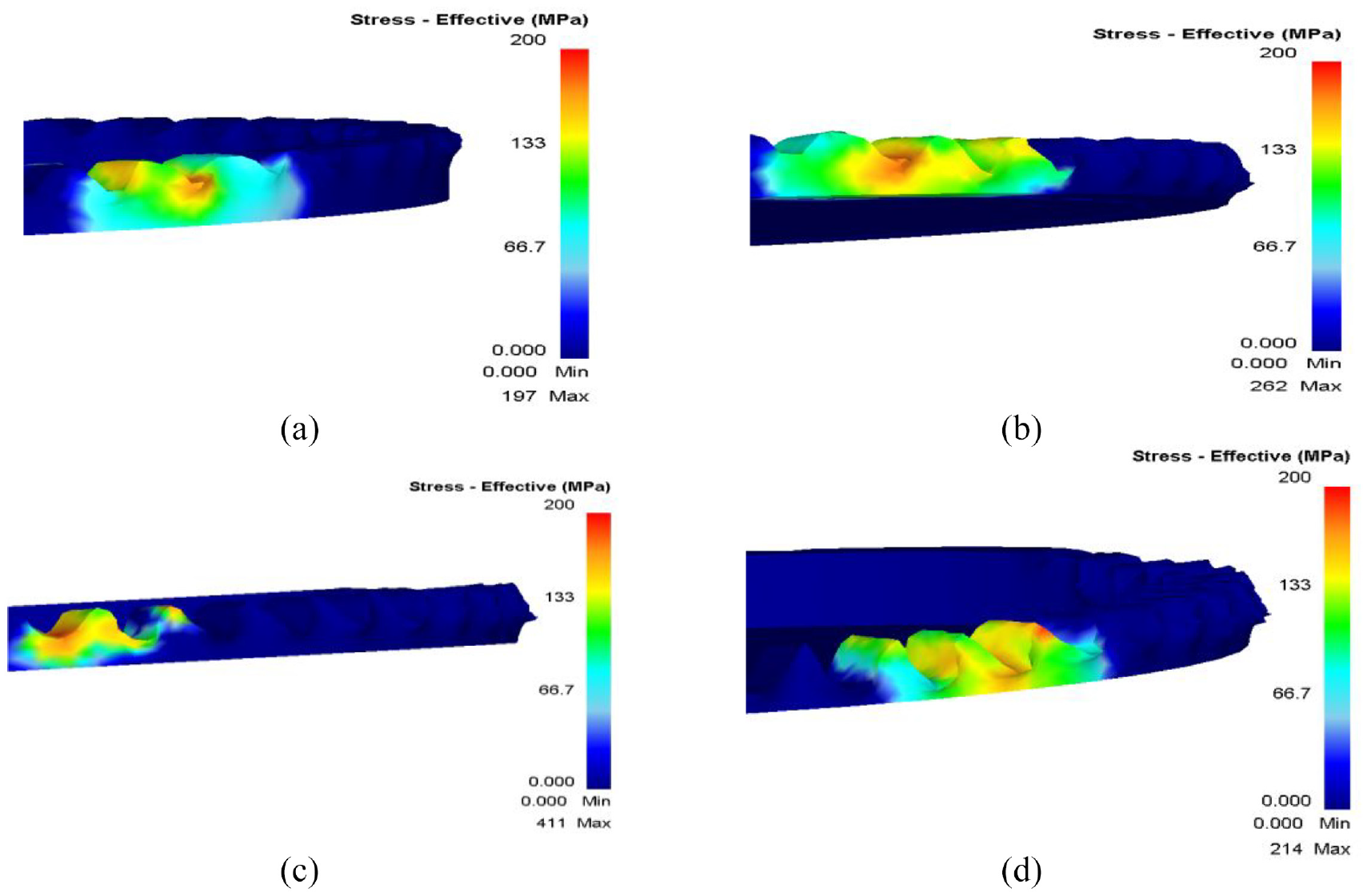
Equivalent stress field of spur surface gear hot rolling: (a) feed 20%, (b) feed 60%, (c) feed 100%, and (d) finishing stage.
The above analysis shows that with the continuous increase of feeding rate, the tooth tops of the mold squeeze the tooth grooves of the gear blank. As the stress begins to diffuse from the surface of the gear blank to its bottom, and the stress distribution area expands gradually.
Analysis of the equivalent strains for hot rolling spur face gear
In the hot rolling processes of spur face gear, the equivalent strain distributions of the gear blank in different stages are shown in Figure 8. When the feeding rate is 20%, as shown in Figure 8(a), the equivalent strain is mainly distributed on the surface area of the gear blank, which is only limited to the area where the gear blank contacts the mold gear. The rolling of spur face gear is mainly a process of local deformation of the gear blank surface. When the feeding rate reaches 60%, shown in Figure 8(b), the equivalent strain increases, which changes the most obviously at the tooth root. The equivalent strain on the tooth surfaces on both sides of the gear blank increases continuously and develops toward the tooth thickness. The radial equivalent strain area of the gear blank is relatively large and extends to the bottom. When the feeding rate reaches 100%, as shown in Figure 8(c), the equivalent strain of the whole gear blank tooth profile increases to a certain extent, and further deformations take place in the tooth thickness and the radial direction. In the finishing stage, as shown in Figure 8(d), when the gear teeth of the gear blank have been formed, it can be seen that the equivalent strain is evenly distributed in the direction of the tooth profile. Seen from the whole rolling evolution process, the maximum equivalent strain in different stages occurs in the direction of the midpoint of the tooth width inclined to the tooth root area.

Equivalent strain fields of hot rolling spur face gear: (a) feed 20%, (b) feed 60%, (c) feed 100%, and (d) finishing stage.
It can be seen from the above analysis that the tooth top of the mold continuously extrudes the tooth groove of the gear blank, whose deformation is the largest, and the maximum strain occurs inclined to tooth root.
Analysis of the metal flow characteristics of hot rolling spur face gear
In the process of hot rolling spur face gears, the internal structure of metal for the gear blank is elongated along the direction of the metal flow, and the internal metal fiber structures continuously distributed macroscopically. The continuously distributed metal streamlines make the metal show various anisotropy, and the tensile strength, plasticity, and toughness in the horizontal direction are obviously better than those in the vertical direction.
Applying the meshing function in the post-processing functions of DEFORM, the horizontal line on the specified vertical section of the gear blank was set to replace the metal streamline in the horizontal direction. As a result, the continuity and changes of the metal streamlines of the gear blank in the rolling process could be clearly presented, as shown in Figure 9. In the entire rolling process of the face gear, the metal streamlines of gear blank were not broken, but continuous, which was conducive to maintaining the original mechanical properties of the metal. During the rolling process, it could be clearly seen that the metal streamlines were bent to different degrees, among which these on the surface of the gear blank were the most complex. It revealed that the metal on the surface of the gear blank changes the most during the rolling process of the face gear. The farther away from the tooth surface inward, the smaller the changes of metal streamline. In the face gear tooth profile, the metal streamlines were gradually dense and bent to the tooth root. In the process of rolling, the metal material flowed to the tooth top of the face gear. The metal at the bottom of the tooth groove of the blank was squeezed by the mold gear, and the density of the metal streamlines at the tooth root increased, which was conducive to improving the bending strength of the tooth root of the face gear. It could also be observed from Figure 9 that the left and right metal streamlines were asymmetric, which indicated that the metal flow velocities on the left and right surfaces of the mold gear teeth were inconsistent. Under the effects of the tangential friction between the mold and the tooth surface of the gear blank, it would eventually lead to the metal sharpening on the top of the gear teeth for the gear blank.

Metal streamline of rolling face gear: (a) feed 20%, (b) feed 60%, and (c) feed 100%.
Experimental study on hot rolling spur face gear
Experimental devices
The experimental devices consisted of the rolled face gear and its drive box, the mold gear and its drive box, the balance face gear and its support device, two hydraulic slides and the control system, as shown in Figure 10. Five movements could be realized, which were the rotary movement of the mold gear, the rotary movement of the rolled face gear, the rotary movement of the balance face gear, the axial movement of the rolled face gear, and the axial movement of the balance face gear.
The hydraulic sliding table was driven by the hydraulic system, which realized axial feed for the hot rolling test-bed. The hydraulic system could ensure the axial force of the rolled face gear and that of the balance face gear were equal, to make sure the balance of radial forces on both sides of the mold gear. The face gear to be rolled and the mold gear were reduced driven by the servo motor through the worm and worm gear, which rotated according to the set speed ratio.
When the rolled gear blank was heated to a certain temperature and depth, the sliding table fed driven by the hydraulic system. After reaching the specified position, the mold gear began to perform the forced generating motion with the blank. With the continuous increase of feeding depth, when the sliding table moves to the set ending position, namely the dead point, the teeth of the face gear would be formed and the rolling would finish.
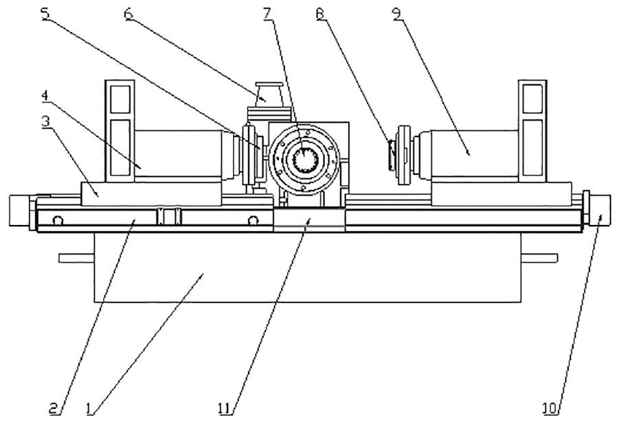
Experimental devices of hot rolling face gear. 1: Test-bed base. 2: Feeding rail of the rolled face gear. 3: Feeding slide of the rolled face gear. 4: Drive box of the rolled face gear. 5: The rolled face gear. 6: Drive box of the mold gear. 7: The mold gear. 8: The balance face gear. 9: Supporting device of the balance face gear. 10: Feeding slide of the balance face gear.
Hot rolling forming
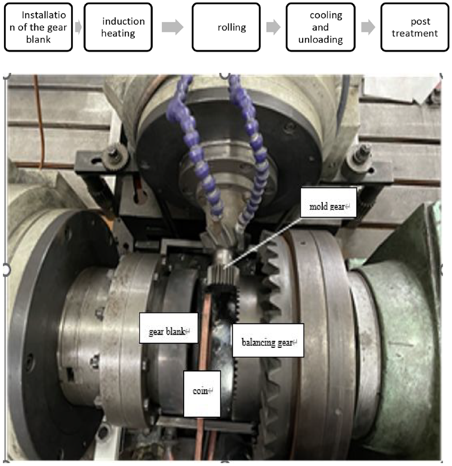
The testing field of hot rolling face gear is shown in Figure 11. The main steps of the rolling experiment were presented as the followings:
In the rolling process, the face gear blank and the mold gear were forced to form a generating motion with a constant rolling ratio. The contacting area between the gear blank and the mold gear was lubricated with 30% graphene solution. The hydraulic slide fed at a fixed rate.
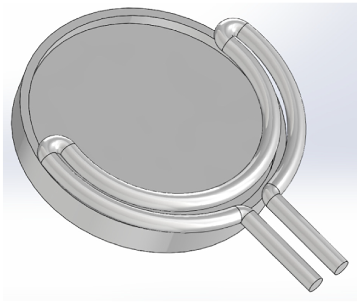
The power supply of heating the gear blank was 75 kW. Figure 12 shows the structural diagram of the heater. At the frequency of 6000 Hz, the heating depth was 10 mm, as shown in Figure 13.
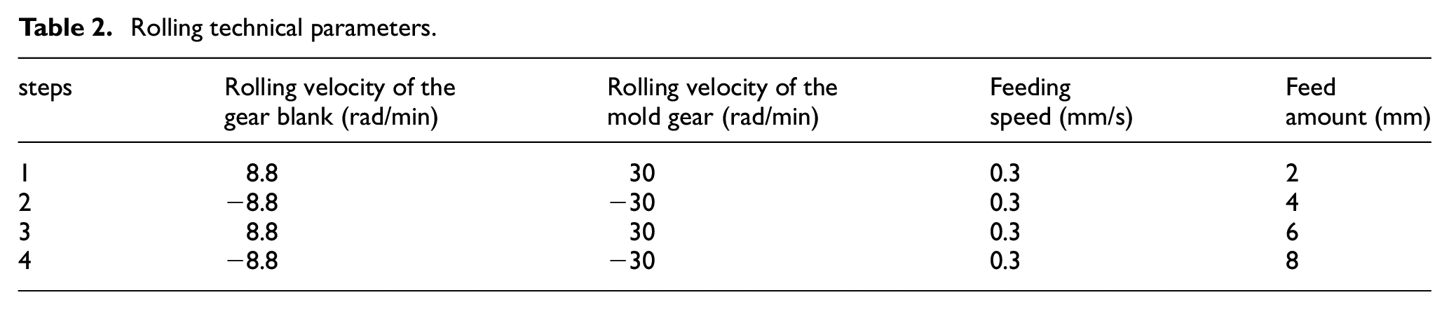
Table 2 shows the set rolling technical parameters. While the rolled face gear was fed axially, the gear blank was being rolled reversely and repeatedly by the mold gear with a constant rolling ratio.
After feeding to the target depth, the induction heating power supply was turn off, the hydraulic slide was held back, and the gear blank was out of engagement with the mold gear. The gear blank began to be cooled naturally. The rolled spur face gear is shown in Figure 15.
The rolling device of the hot rolling test.
Structural diagram of the heater.

Heating of the gear blank.
Rolling technical parameters.
The influence law of various parameters during rolling is shown in Figure 14.

Relationship of each factor level and the proportional coefficient.
By combining orthogonal experiments, the optimal combination of machining parameters could be obtained as followings: rolling temperature 950°C, friction factor 0.3, feed rate 0.3 mm/s, and the rotating speed of the gear to be processed 30 r/min. By analyzing the range values, it could be seen that the degree of influences of four factors on metal flow line defects was sequentially as the followings: feeding speed, friction factor, initial rolling temperature, and rotating speed of the gear to be machined. Then, the combination of optimal and non-optimal parameters were used to roll respectively, and the forming results are shown in Figure 15.

Hot rolled spur face gear: (a) vertical view of the spur face gear, (b) formed by non-optimal parameters, and (c) formed by optimal parameters.
Tooth surface error detection
The accuracy of the rolled face gear by the optimum parameters was tested by the Gleason650GMS, the gear measuring center, as shown in Figure 16.
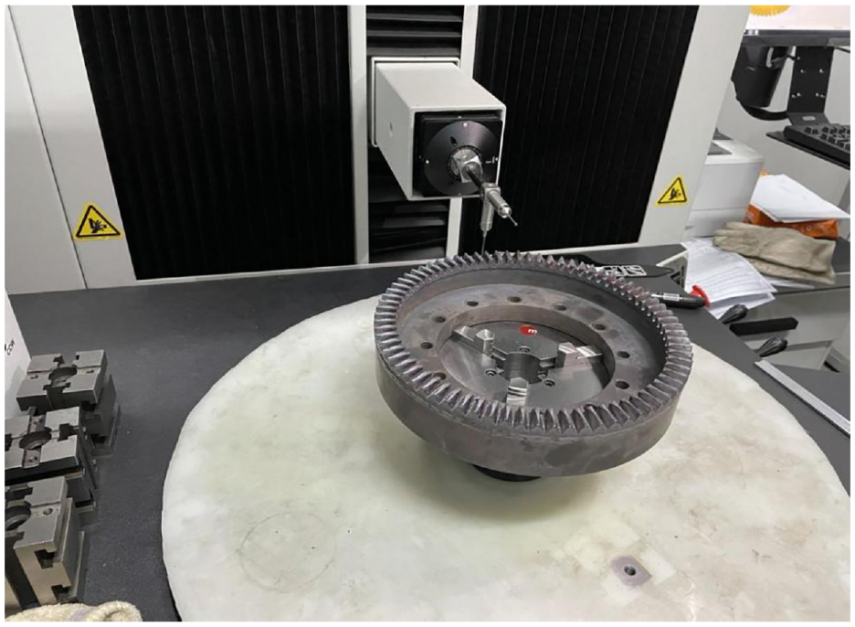
Tooth surface error detection.
The results of measurement are shown in Figure 17. The maximum cumulative deviation of tooth pitch, Fp, was 172.6 μm, Grade 10, and the Minimum Fp was 136.7 μm, Grade 9. The cumulative deviation of single tooth pitch was Grade 10. It showed that the hot rolling process could be applied in machining the face gears with certain accuracy, which would be acceptable after tooth surface finishing machining.

Test report.
Observe the metal flow lines at the top, surface, and root of the gear tooth, and obtain the morphological changes of the metal flow lines at different parts of the gear tooth, as shown in Figure 18. It can be seen that the metal flow line at the root of the tooth is the densest and most obvious; The metal flow lines at the tooth top, tooth surface, and tooth root positions are all distributed along the direction of the mold gear rolling, which is, along the tooth profile of the gear; The direction of the streamline is perpendicular to the normal direction of the tooth surface, indicating that during the rolling process, the material was subjected to the rolling force and the extrusion of the tooth surface of the mold gear, flowing from the tooth root to the tooth top, and forming a metal streamline distributed along the tooth profile on the tooth surface. The results indicated that upgrade metal streamline distribution could be obtained through hot rolling machining, which verified that the experimental results were basically consistent with the numerical simulation results.

Sample metal flow diagram: (a) tooth top, (b) tooth root, and (c) tooth surface.
Conclusions
The characteristics of equivalent stress field, equivalent strain field and material flow of hot rolling spur face gear were analyzed by numerical simulation. It was found that the maximum stress occurred at the contacting areas between the mold gear and the gear blank. The maximum equivalent strain field appeared at midpoint of the tooth width inclined to the tooth root area. The maximum density of the metal streamlines was at the tooth root, which were beneficial to improve the bending strength of the tooth root.
The rolling test-bed was set up, based on which the face gear testing piece was rolled. The tooth surface error of the testing piece was detected on the gear measuring center, whose report showed that the machined face gear has a certain accuracy. As a result, the feasibility of the hot rolling face gear was verified technically.
Footnotes
Handling Editor: Chenhui Liang
Author contribution
All the authors contributed significantly to the work with the order provided.
Declaration of conflicting interests
The author(s) declared no potential conflicts of interest with respect to the research, authorship, and/or publication of this article.
Funding
The author(s) disclosed receipt of the following financial support for the research, authorship, and/or publication of this article: This work is supported by the National Major Science and Technology Project (HT-J2019-VII-0017-0159) Funds, the Natural Science Foundation of China (Grant Nos. 51975185, 52005157, 52175049), and the Science Foundation of Post PhD (Grant No. 2021M690051).
Ethical approval
Not applicable.
Consent to participate
Not applicable.
Code availability
Not applicable.
Consent to publication
All the authors have reached agreement for publication.
Data availability
The datasets used in our study are available from the corresponding author on reasonable request.