
Abstract
With the development of industrial technology, the application of large diameter-thickness ratio integral discs in various high precision vessels is becoming more and more important. At present, the forming processes of large-diameter disc mainly includes welding and multiple local upsetting, but these processes exhibit large defects and cannot meet the requirements of industry. Therefore, a new metal plastic forming technology, namely rotary forging with multi-cone rolls (MCRs) is proposed to integrally form large diameter and ultra-thin discs. The forming process was simulated by DEFORM-3D finite element analysis software, and the deformation characteristics of MCRs disc were revealed. The results show that the axial plastic deformation of disc can be divided into three stages. In the first stage, the plastic deformation area was basically symmetrical, and the deformation was relatively stable. In the second stage, the plastic deformation area on both sides was different, which was in the unstable stage and easy to produce defects. In the third stage, the plastic deformation area was approximately symmetrical for a long time, and the plastic deformation was stable. At the same time, the influence of process parameters on the form characteristics of MCRs, the main defects in the deformation process and the preventive measures were studied. The research results are helpful to better understand the metal plastic forming technology of MCRs and promote the further development of MCRs.
Keywords
Introduction
With the development of modern industry, the demand of all kinds of high-pressure sealed vessels for integral forming parts is increasing. The cylindrical shell of large hydrogenation reactor and large spherical tank for deep-sea exploration are all produced by forging process of large-diameter disc parts. The stretch forming of the rocket fuel storage tank requires an integral disc with a diameter of 4 m and a thickness of 8 mm, and an integral disc with a diameter of more than 8 m is required for the end plate and head plate of the nuclear reactor pressure vessel and other high-pressure vessel. At present, the main forming methods of large-diameter disc are welding, cutting sheet metal, and multiple local upsetting of plate. However, these processes have high material consumption, low production efficiency, and poor product performance, which cannot meet the needs of nuclear power, chemical industry, military industry, aviation, and other departments for integral forming parts.
Rotary forging is an advanced metal plastic forming technology, which is widely used to manufacture the engineering parts such as disc, ring and gear, and it offers the following advantages: low forging pressure, high machining accuracy, and low level of noise. The forming force is 1/10–1/5 of the traditional forging equipment and the dimensional accuracy of rotary forging parts is 0.02 mm. Therefore, many scholars have studied rotary forging.
Loyda et al. 1 studied the effect of rotary forging on the microstructure behavior of a nickel-based superalloy. Zhang 2 studied the parameters of force and energy during the rolling process and derived the calculation formula, it can provide the basis for equipment development. Pérez 3 analyzed micro-structural and texture evolution of high strength materials during cold rotary forging. Canta et al. 4 used lead and steel materials to carry out rotary rolling forming test, and obtained the energy distribution of rotary rolling process. Jin et al. 5 optimized the cold orbital forging of component with deep and narrow groove. Liu et al. 6 studied four tracks of the cold orbital forging and the influence of unequal eccentricity on the movement of swing head. Zhu et al. 7 studied the forming of rotary forging with double symmetry rolls. For the research on the forming of discs and rings, Wang et al.8,9 summarized a new metal flow model using 3D rigid-plastic finite element method, and revealed the deformation mechanism of rotary forging of ring. Liu et al.10,11 analyzed the mushroom effect and center-thinning of rotary forging of the cylindrical workpiece. Oh and Choi 12 analyzed the central defects in the forming process of disc and derived the formula for the center-thinning of the disc. Zhou et al.13,14 studied the deformation distribution and forming defects in the process of rotary forging of the cylindrical workpiece. Zheng et al.15–17 studied the flow stress curve of titanium alloy disc at different temperatures, and analyzed the law of metal flow and the strain distribution during forging. Han and Hua 18 and Hua and Han19,20 conducted further study on the plastic and wear deformation mechanisms of cylindrical and ring workpiece.
However, the traditional rotary forging is mainly used to form small and medium-sized parts with a diameter less than 600 mm, which large parts cannot be formed integrally and greatly limits the development of rotary forging technology. Therefore, in order to meet the needs of the industry for large-diameter discs and expand the application of rotary forging technology, a new metal plastic forming technology, namely rotary forging with multi-cone rolls (MCRs) is proposed to solve the above problems. Through the establishment of three-dimensional finite element model, a large number of simulation calculations were carried out to reveal the plastic deformation law of MCRs and the influence of process parameters on the forming of disc parts. In addition, the twin rollers rotary forging equipment was slotted and transformed into MCRs equipment, and the effectiveness of the technology for large diameter disc parts was verified by experiments. The research results are helpful to further understand the MCRs and promote the further development of rotary forging technology.
Working principles of MCRs
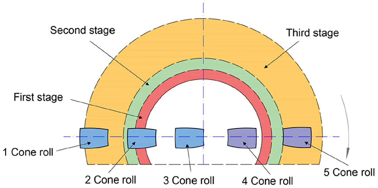
MCRs is a metal plastic forming technology with odd cone rolls and more than three. The working principle of MCRs is shown in Figure 1. Taking five cone rolls as an example, the cone rolls are distributed on both sides of the press, with odd (3) cone rolls on one side and even (2) cone rolls on the other side. The sliding cross beam drives the cone roll to move downward. Simultaneously, the workpiece rotates around the press axis driven by rotating lower die. When the cone roll contacts the workpiece, it rotates around its own axis driven by the friction force and compresses the workpiece to realize the rotary forging of the workpiece. In the forming process, the part of the same side cone roll that has not been rolled produces a step, which is rolled by the cone roll on the other side after the lower die rotates half circle. When the workpiece reaches the predetermined height, the upper die stops feeding, and the lower die continues to rotate the finishing surface. Finally, the workpiece is formed.

Schematic diagram of MCRs.
Finite element modeling simulation procedures
Geometry models and meshes
This paper performs a 1:20-shrink-ratio finite element simulation calculation on a 10-m disc. The forging drawing and geometric model of product are shown in Figure 2. The upper die of MCRs was composed of five cone rolls with equal height distribution along the diameter direction of the workpiece. When the cone rolls were distributed, it is necessary to ensure that the steps generated by the gap between the two cone rolls can be flattened by the other cone roll in the lower half of the circle. In order to ensure the fixation of the workpiece in the lower die and prevent the billet from shaking, a 3 mm groove was added in the lower die, so the thickness of the billet was increased by 3 mm (bottom step) accordingly. The die structure diagram and three-dimensional FE model are shown in Figures 3 and 4.
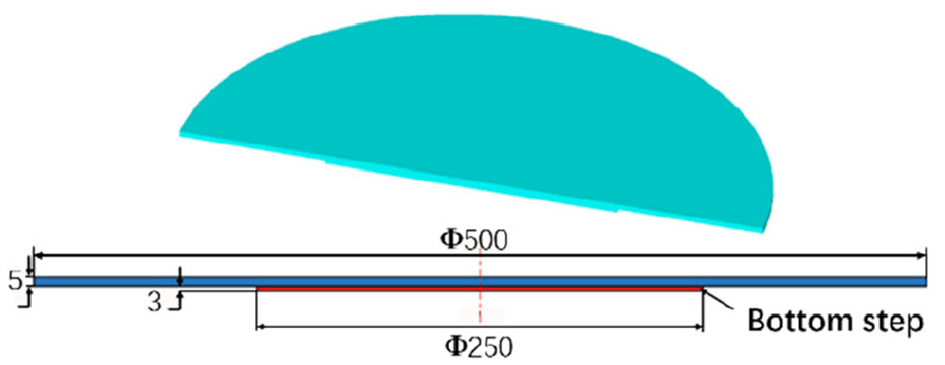
Forging drawing and geometric model of product.

3D FE model of MCRs.
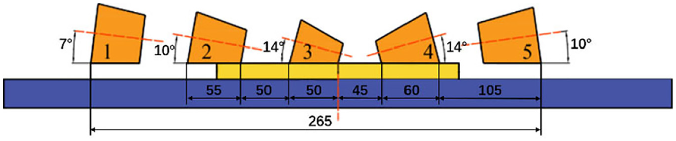
Structure diagram of MCRs.
In order to improve the accuracy and resolution of geometric and field variables, the workpiece was discretized using a tetrahedral mesh with 33,424 elements and 7680 nodes. The workpiece material is AISI 1045 (elastic-plastic material), and the material properties at the elastic stage of the material are shown in Table 1.
Material property data.

Boundary conditions and process parameters
Since the rotary forging adopted in this paper belongs to hot rotary forging, the maximum friction condition was selected in the simulation. Friction in the model was defined as:

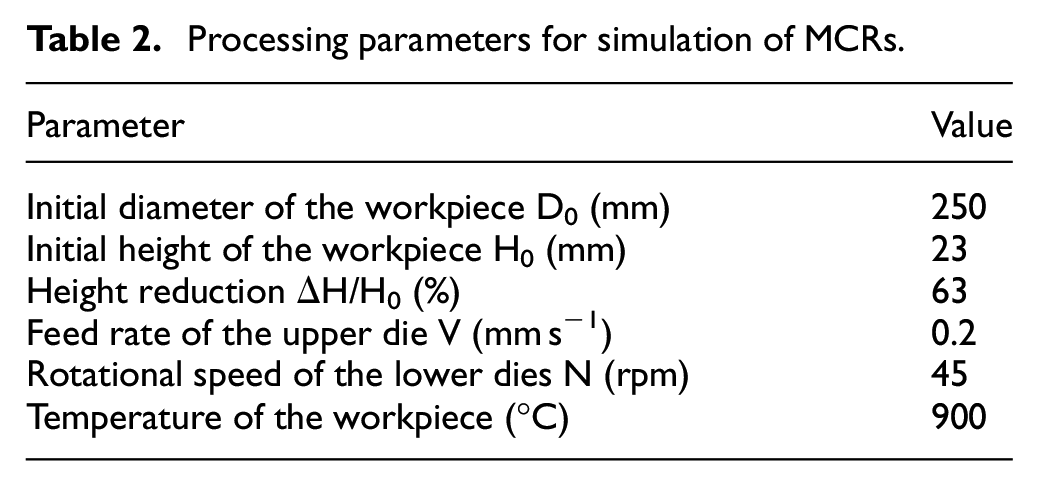
Where τf is the friction stress, m is the friction factor and k is the shear yield stress. Due to the asymmetrical forces on both sides of MCRs, the friction factor was set as 0.7 in order to prevent the workpiece from shaking. The ambient temperature was defined as 20°C, the convective heat transfer coefficient between workpiece and die and air was set as 0.02 N/s/mm/°C, and the heat transfer coefficient between the workpiece and the die was set as 5 N/s/mm/°C. Other process parameters are shown in Table 2.
Processing parameters for simulation of MCRs.
Results and discussion
Deformation characteristics of MCRs
Compared with traditional rotary forging, MCRs has the characteristics of highly nonliner, local contact, compex axial, radial and circumferential dynamic plastic flow process. Due to the motion of MCRs is the compound motion of five cone rolls and the structure is asymmetric, a certain height of steps will be formed on the surface during the forming process. These factors make the plastic deformation of MCRs more complicated than traditional cold rotary forging.
Deformation characteristics of axial section of the workpiece
In order to explore the plastic deformation characteristics of MCRs, the axial and surface PEEQ (equivalent plastic strain) of the cylindrical workpiece were analyzed in detail. Figure 5 shows the distribution of deformation stages, and Figure 6 shows the PEEQ distribution of the disc in the axial direction. It can be seen from Figures 5 and 6 that the plastic deformation of the disc formed by MCRs can be divided into three stages. The first stage, which was the initial stage of deformation, at this time the workpiece was only contact with the rolls 2, 3, and 4. As with traditional rotary forging, the metal on the upper surface of the cylindrical workpiece first satisfied the yield condition and started plastic deformation, and the plastic deformation zone gradually expanded along the radial and axial direction, as shown in Figure 6(b) to (d). With the increase of forming time, the contact area between cone rolls on the left and the workpiece increased gradually, and the transfer range of the plastic deformation zone was gradually greater than that in the right part, as shown in the local plastic deformation Figure 6(d′) of 6(d). From the first stage, it can be seen that the plastic deformation zone was basically symmetrical distribution at the beginning deformation of MCRs, which indicated that the difference in force between both sides was small and the initial deformation was relatively stable. Figure 6(b′) is the local plastic deformation diagram of Figure 6(b). From Figure 6(b′), it can be seen that the expansion of plastic deformation zone along the axial and radial direction at the beginning was similar to the propagation of water wave, which indicated that the cylindrical workpiece conformed to the transmission characteristics from the upper surface to the lower surface.
Distribution of the deformation stage.

PEEQ in the axial direction of the cylindrical workpiece: (1)stage 1, (2)stage 2, and (3)stage 3.
Figure 6(2) shows the second stage of the deformation.
Due to the expansion of plastic deformation zone, the plastic deformation zone gradually penetrated the whole workpiece, as shown in Figure 6(e). As the forming process continued, the contact area with the roll 4 began to produce large deformation zones, as shown in Figure 6(f). Under the direct action of the roll 4, the metal deformation degree of the contact area was relatively maximum. Due to the rotation of the workpiece and the rolling of the left cone rolls, a large deformation zone was also generated in the left part, and the plastic deformation zone gradually expanded in the axial and radial directions, as shown in Figure 6(g). With the increase of the contact area between the left cone roll and the workpiece, the difference of the plastic deformation zone on both sides of the workpiece decreased, as shown in Figure 6(h). In the second stage, the difference between the plastic deformation zones on both sides increased, which made the second stage unstable and prone to various defects.
Figure 6(3) shows the third stage of deformation. The workpiece began to contact with roll 5, as shown in Figure 6(i). As the contact area of the right cone rolls increased, the plastic deformation zone difference between the two sides decreased gradually, as shown in Figure 6(j). And with the increase of time, the diameter of the workpiece increased gradually, the contact area between the workpiece and the lower die increased, thus leading to the compensation effect of friction on the unbalanced force on both sides of the cone roller was increased. At the same time, the friction also contributed to the symmetrical distribution of plastic deformation zones on both sides. With the increase of the diameter of workpiece, the workpiece began to contact with roll 1, and the plastic deformation zone was still symmetrical, as shown in Figure 6(k). Finally, with the continuous feeding of the upper die and the gradual expansion of the plastic deformation zone, the workpiece was gradually formed, as shown in Figure 6(n). It can be seen from the three stages that the plastic deformation zone was approximately symmetrical distributed for a long time during the forming process, which indicated that the deformation process was stable and the workpiece was in a stable forging state.
In the forming process, the edge region was pushed by the internal plastic deformation zone, and small plastic deformation occurred. The edge of the cylindrical workpiece was in a state of small plastic deformation and elastic deformation. In the design of MCRs, the roll 3 was in direct contact with the center, and the central region was not in the state of small plastic deformation and elastic deformation, which made the plastic deformation distribution of the whole cylindrical workpiece more uniform.
Surface plastic deformation of MCRs
In the process of MCRs of disc, the contact area between the two sides of the cone rolls and the workpiece changed dynamically. In addition, in the forming process, the surface will form steps due to the design principle of MCRs. Therefore, in order to further study the plastic deformation characteristics of MCRs, the surface plastic deformation of the cylindrical workpiece was studied in detail.
Figure 7 shows the surface PEEQ distribution of the cylindrical workpiece in different time. It can be seen from the Figure 7 that the surface PEEQ distribution of the cylindrical workpiece exhibited a water wave pattern, extending from the central region to the edge of the workpiece, and was approximately symmetrical. At the beginning of the deformation, the maximum deformation zone was generated in the contact area between roll 4 and the workpiece, as shown in Figure 7(a). Due to the small difference of the PEEQ value in each region at the beginning, and the small feed amount, the duration of the first stage was longer. As a result, the plastic deformation zone in a certain range of strain value expanded rapidly on the surface to reach the initial penetration of the whole cylindrical workpiece, as shown in Figure 7(b). At this time, the surface strain value was not much different, and it was in the process of stable forming. As the forming process continues to reach the second stage, a large plastic deformation zone was generated in the contact area between the roll 4 and the workpiece. At this time, the surface plastic deformation zone was asymmetric, and the deformation process was easy to be unstable, as shown in Figure 7(c). The large plastic deformation zone gradually expanded in the radial direction, and some metal in the small plastic deformation zone was fused to the large plastic deformation zone across the plastic deformation zone. In addition, some metal in the maximum strain zone expanded to the small strain zone across the maximum strain zone, forming a new composite strain zone with the metal in small plastic strain zone, as shown in Figure 7(d). Finally, the surface plastic deformation zone where the strain changed from small to large in the radial direction and then decreased successively was formed, as shown in Figure 7(e). With the expansion of the plastic deformation zone, the workpiece was gradually formed, as shown in Figure 7(f).

Surface PEEQ distribution of the cylindrical workpiece.
Influence of the process parameters on MCRs
In the process of MCRs, the cone roll is in direct contact with the central region during the design of the cone roll, the defects of center-thinning and center-thickening will not occur. However, due to the rapid rotational speed of the cone roll, defects such as flying chip and folding were easy to occur during the forming process, as shown in Figures 8 and 12 (Figure 12 will be analyzed later). Folding detroys the integrity of the surface of the cylindrical workpiece, leaving gaps in the workpiece, and easily generating stress concentration under heavy load working conditions, causing crack propagation, which may cause fatigue fracture of the workpiece. Flying chips are the main reason for the folding of MCRs, and they are easily involved in the cone roll, which affects the surface quality of the workpiece.

Flying chip defect in forming process.
In order to reduce the defects in the process of rotary forging and study the forming process of MCRs in detail, several main process parameters (Rotational speed of lower die N, Initial diameter of blank Φ, Bottom step thickness H) were analyzed in this paper. In order to study the influence of the initial diameter of the blank Φ on MCRs, Φ = {240, 250, 260, 270, 280, 290, 300} mm was selected, and other process paremeters are consistent with Table 2. In order to study the influence of the lower die rotational speed N on MCRs, N = {30, 35, 40, 45, 50, 55, 60} rpm was selected, and other process paremeters are consistent with Table 2. In order to study the influence of bottom step thickness H on MCRs, H = {1, 2, 3, 4, 5} mm was selected, and other process paremeters are consistent with Table 2.
Influence of initial diameter of the disc
According to the plastic deformation law of MCRs, the larger the diameter of the blank was, the larger contact area between the blank and the lower die was, and the greater compensation effect of friction on the unbanlanced forces on both sides was, which made the forging process more stable. And the larger the diameter of the blank, the plastic deformation will go beyond the first and second stages directly to the third stage, the forming process in the third deformation stage was more stable, which will reduce various defects in the forming process, thereby improving the quality of the formed workpiece.
In the simulation process of DEFORM-3D software, if there are flying chip defects, the system will remesh and remove more than one third of the tetrahedron of mesh distortion, thus reducing the amount of calculation. Therefore, the degree of the defect can be judged by the volume loss during the simulation process. Figure 9 shows the variation curve of the influence of the initial diameter of the blank on the volume loss, and Figure 10 shows the position change diagram of the contact between the blank with different initial diameter and the upper die. It can be obviously seen from Figures 9 and 10 that as the initial diameter of the blank increased gradually, the closer the blank was to the roll 5, the smaller the volume loss percentage was. When the initial diameter of the blank was less than 270 mm, the volume loss was serious. When the diameter of the blank was greater than 270 mm, the volume loss was greatly reduced and less than 1.2%, almost no volume loss. That is to say, with the increase of the initial diameter of the billet, the less flying chips, the smaller the volume loss and the more stable the swaging process.

Influence of initial diameter of blank on volume loss.

Contact position between the blank with different initial diameter and the upper die.
Figure 11 is a schematic diagram of folding defects after forming with different initial diameters of the blank. It can be seen from Figure 11 that the folding defects gradually decreased with the increase of the initial diameter of blanks. A large reduction occurred when the initial diameter was larger than 270 mm, and there was almost no folding defect when the initial diameter was 300 mm. The folding of MCRs of discs was mainly produced at the same time with the flying chip. In order to better understand the causes of defects and the relationship between the initial diameter of the workpiece, the following will be analyzed in detail.

Schematic diagram of folding defects after forming with different initial diameters of the blank.
Figure 12 shows the contact metal flow process of the cone roll in MCRs. It can be seen from Figure 12 that in the process of MCRs of disc, due to the too high rotational speed of the cone roll and blocking effect of cone roller on the metal flow of step, metal accumulation was formed in contact area, and then flying chip defect was formed. Under the action of the cone roll, the metal mainly flowed downward along the cone roll. If the thickness of the blank was thick, the resistance of the metal flowing downward along the cone roll was large, and some of the metal flowed in the opposite direction, thus gradually forming flying chip defect. After the formation of the flying chip, the metal flowed inward under the pressure of the cone roll, which was easy to form folding in the intersection of the flying chip and the workpiece, and the flying chip involved in the cone roll was also easy to produce a large number of folding defects. With the increase of the blank diameter, the thickness of the blank was smaller, and the plastic deformation zone was easier to penetrate the workpiece for axial metal flow, which can effectively reduce the flying chip and folding defects. In addition, the increase of the blank diameter increased the contact area between the blank and the lower die, and the compensation effect on the left and right unbanlanced force of the cone rolls increased, which made the rotary forging more stable and helps to reduce defects.

The contact metal flow process of the cone roll in MCRs.
Influence of rotational speed of the lower die
In the design of MCRs, the lower die rotation drove the blank to rotate together, and the cone roll rotated under the friction between the cone roll and the blank. In this paper, the axis of the cone roll pass through the center of the blank except for the cone roll 3. The cone roll 3 is small, which has little tensile effect on the central region, and the central is prone to thickening. In order to avoid this defect, the cone roll 3 was designed to directly contact the central region, resulting in a certain distance between the axis of the cone roll 3 and the center. Due to the small distance, the calculation was based on the axis of the cone roll 3 passing through the center.
The relationship between the rotation of the cone roll and the revolution of the lower die is shown in Figure 13. In the process of MCRs, the cone roll is rolling relative to the workpiece, and there is no relative sliding, then the equation is:

Relationship between the rotation of the cone roll and the revolution of the lower die.

obtained from equation (2)

where n1 is the lower die rotational speed, n2 is the cone roll rotational speed. According to the above formula, the cone rolls rotational speed under different lower die rotational speed was obtained, as shown in Table 3.
The cone rolls rotational speed under different lower die rotational speed.

Figure 14 shows the variation curve of volume loss at different lower die rotational speeds. It can be seen from Figure 14 that with the increase of the lower die rotational speed, the volume loss percentage decreased ripidly, and then a certain fluctuation occurred, and finally the volume loss percentage starts to increase again. At low rotational speed, the force of the cone roll on the blank was reduced, which made it difficult to form metal accumulation at the contact. However, the volume loss percentage increased significantly at low rotational speed, mainly because the height of the steps of per unit turn was higher, and the metal at the contact was difficult to flow downward, thus formed metal accumulation. Although the reduction of rotational speed can reduce the metal accumulation at the contact, the increase of step height at low rotational speed was the main factor, and more obvious the effect was with the lower rotational speed, which led to the increase of volume loss and flying chip defects. When the rotational speed continues to increase, the height of the step per unit turn decreased, which made the force at the contact between the cone roll and the blank decreased, and at the same time, the increase of the rotational speed made the force at the contact increased. In this stage, the two factors alternately dominated, showing the fluctuations in volume loss. When the rotational speed was greater than 50 rpm, the influence of the rotational speed was dominant, and with the increase of the rotational speed, the larger the volume loss was, the more serious the defect was.

Variation curve of volume loss at different lower die speed.
Figure 15 shows the folding defects at different lower die rotational speed. Because flying chip was the main cause of folding, the change of folding defect with rotational speed was basically consistent with the change of volume loss percentage with rotational speed. It can be seen from Figure 15 that no matter how the lower die rotational speed changed, the folding defect decreased gradually with the increase of the initial diameter of the blank. When the initial diameter of the blank was 270 mm, a large number of folding defects occurred. The folding defect increased significantly at low speed, which seriously affected the surface quality of the formed workpiece. The folding defect also increased gradually at high rotational speed, and the defects were least when the loweer die rotational speed was 40 and 50 rpm. Therefore, selecting a reasonable rotational speed was conducive to reduce flying chip and folding defects during forming process.

Folding defects at different lower die rotational speed: (a) Φ = 270 mm, (b) Φ = 280 mm, (c) Φ = 290 mm, and (d) Φ = 300 mm.
Figure 16 shows the influence of different lower die rotational speed on the surface plastic deformation when the initial blank diameter was 300 mm. It can be seen from Figure 16 that the surface plastic deformation of the blank still maintained water waveform change under different lower die rotational speeds, and the plastic deformation of both sides of the blank remained symmetrical during the forming process. With the increase of the lower die rotational speed, the strain value of the large plastic deformation zone tended to increase. The main reason was that with the increase of the lower die rotational speed, the rotational speed of the upper die cone roll increased, which increased the acting energy of the cone roll on the contact area, and finally the greater the lower die rotational speed, the greater the strain value of the large deformation zone.

Influence of different lower die rotational speed on the surface deformation: (a) N = 35 rpm, (b) N = 40 rpm, (c) N = 45 rpm, and (d) N = 50 rpm.
Influence of the bottom step thickness
Due to the large diameter of the disc, in order to improve the Simulation results, the blank thickness was increased by 3 mm (bottom step) to stationary the blank position and prevent the blank from shaking with the rolls. In the simulation study, it was found that the thickness of bottom step had an important influence on the forming and defect. Therefore, this paper studied the influence of different step thickness on forming defects.
Figure 17 shows the variation curve of the volume loss with different bottom step thickness. It can be seen from Figure 17 that when the initial diameter of the blank was greater than 290 mm, the volume loss percentage increased gradually with the increase of the bottom step thickness. When the initial diameter of the blank was less than 290 mm, the volume loss percentage gradually increased when the bottom step thickness was less than 4 mm, and decreased sharply when the bottom step thickness was greater than 4 mm. It can be seen from the plastic deformation characteristics of MCRs that the contact area between rolls 2 and 4 and the workpiece was the main area of volume loss due to its large thickness. With the increase of the bottom step thickness, the blank thickness at the contact of rolls 2 and 4 gradually increased, and the metal at the contact between rolls and workpiece was more difficult to flow downward, and it was easier to form metal accumulation, resulting in a gradual increased of volume loss percentage.

Variation curve of the volume loss with different bottom step thickness.
When the bottom step thickness reached a certain value, the volume loss decreased, which was contrary to the conclusion of the analysis. Therefore, this chapter analyzed this in detail. Figure 18 shows the metal flow at the contact of MCRs of disc. R+ represented the flow outward along the radial direction, and R− represented the flow inward along the radial direction. The contact metal between the surface step and the cone roll flowed downward along the cone roll, but also to both sides of the cone roll. Since the resistance of the metal flowed inward was greater than the resistance of the metal flowed outward, the innner and outer flow boundary at the entrance of the step was close to the outer edge of the step, and the innner and outer flow boundary at the exit of the step was close to the inner edge of the step. With the increase of the step thickness, it was more difficult for the plastic deformation zone to expand in the axial direction when th blank thickness was large, which made it easier for the metal at the step contact to flow in the radial direction, reducing the metal accumulation. When the bottom step thickness reached a certain value, although it was more difficult for the metal to flow downward along the cone roll, at the same time the radial outward flow at the contact increased, which can reduce the volume loss.

Metal flow at the contact of MCRs of disc.
Figure 19 shows the folding defects under different bottom step thickness (H). It also can be seen from Figure 19 that the variation of folding defects and volume loss had approximately the same law, with small local differences. When the bottom step thickness was 4 mm, there were more defects, and when the bottom step thickness was 1 mm, the folding defects were the least. With the increase of the bottom step thickness, the folding defects tend to increase. Therefore, in order to reduce the defects in forming and increase the utilization rate of the blank, a smaller bottom step thickness should be selected in production.

Folding defects under different bottom step thickness: (a) Φ = 270 mm, (b) Φ = 280 mm, (c) Φ = 290 mm, and (d) Φ = 300 mm.
Since the blank with initial diameter of 300 mm had the least defects, the plastic deformation of the blank with initial diameter of 300 mm was analyzed under different thickness of bottom step. Figure 20 shows the influence of different bottom step thickness on the surface plastic strain of the disc. It can be seen from Figure 20 that different bottom step thickness had little influence on the forming process, and the forming process was still the gradual expansion of the plastic deformation zone, and the overall plastic strain distribution presented a water wave shape.
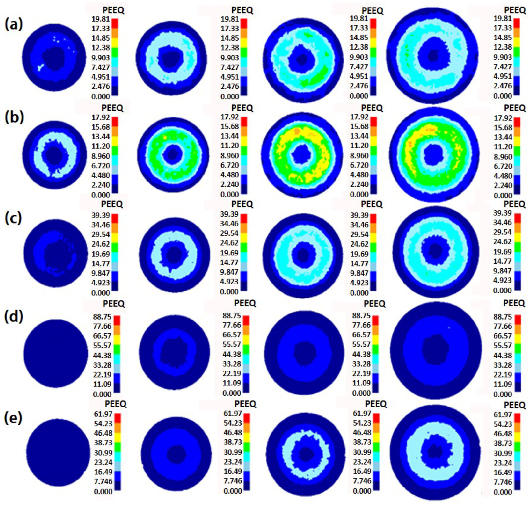
Influence of bottom step thickness on the surface plastic strain: (a) H = 1 mm, (b) H = 2 mm, (c) H = 3 mm, (d) H = 4 mm, and (e) H = 5 mm.
Figure 21 shows the influence of different bottom step thickness on the degree of inhomogeneous deformation. It can be seen from Figure 21 that with the bottom step thickness increased gradually, the degree of inhomogeneous deformation (the difference between the maximum and the minimum PEEQ) generally increased. From the above analysis, it can be seen that large bottom step thcikness can cause the increase of the strain value of the large plastic deformation zone. The minimum strain value decreased with the change of bottom step thickness, while the maximum strain value increased with the change of bottom step thickness. Finally, the total degree of inhomogeneous deformation increased gradually. When the initial diameter of the blank was 270 mm, the degree of inhomogeneous deformation decreased, mainly because the tetrahedron strain was too large during the simulation, which will be removed to remesh, resulting in the change of the total strain. Therefore, there will be some fluctuations during the simulation.

Influence of bottom step thickness on the degree of inhomogeneous deformation.
Feasibility verification of MCRs
As the multi-cone roller rolling is a new forming technology, the research on it is in the preliminary stage, and its equipment has not been developed. In order to verify the feasibility of MCRs technology, based on the original twin-cone roll rolling equipment, grooving was carried out on the roll to simulate the rolling of multi-cone roll. Figure 22(a) shows a rotary forging press with double rolls, which is mainly composed of five parts, such as transmission parts, dies, sliders, hydraulic cylinders, and frames, as shown in Figure 22(b).

500T rotary forging press with double rolls: (a) rotary forging press with double rolls and (b) structure of rotary forging press with double rolls.
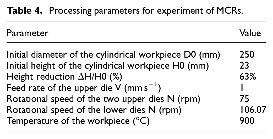
Figure 23 shows the slotted structure of the cone rolls. Processing parameters for experiment are shown in Table 4. Figure 24 shows the formed disc, it has been proved that MCRs is an effective method for manufacturing large diameter-thickness ratio discs.
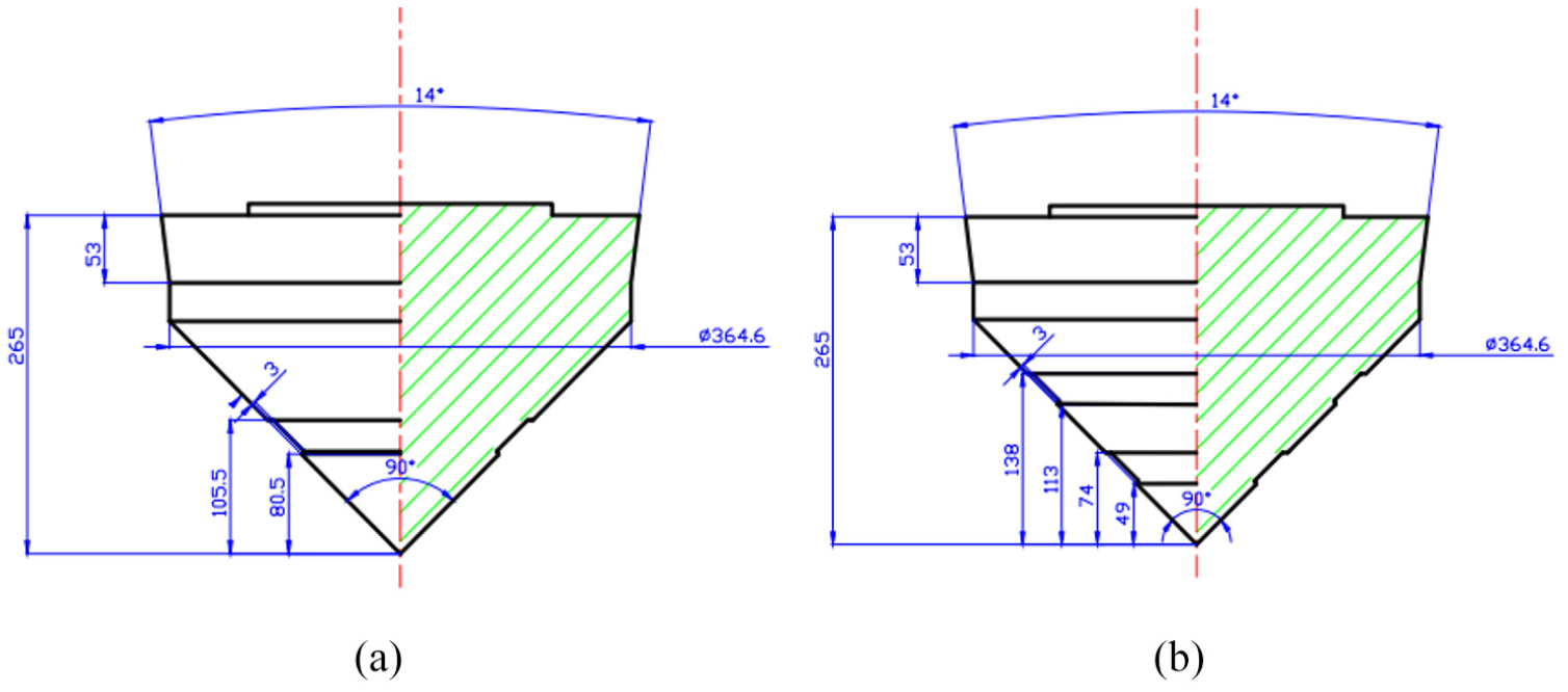
Schematic diagram of the slotted cone rolls: (a) left cone roll and (b) right cone roll.
Processing parameters for experiment of MCRs.
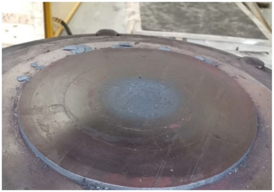
The formed large-diameter disc.
Conclusions
In this paper, a new technology of metal plastic forming, MCRs, was studied, and its plastic deformation law and the influence of process parameters were studied. The following conclusions can be drawn.
The axial plastic deformation of the disc formed by MCRs was mainly divided into three stages. In the first stage, the plastic deformation zone was basically symmetrically distributed, and the deformation was relatively stable. In the second stage, there are differences between the plastic deformation zone on both sides, which was in an unstable stage and prone to various defects. In the third stage, the plastic deformation zone was approxiamtely symmetrically distributed for a long time during the forming process, the plastic deformation was stable, and the workpiece was in a stable rolling state. The distribution of surface PEEQ of the disc was water wave shape, which was approxiamtely symmetrical.
The larger the initial diameter of the workpiece was, the smaller the axial thickness was, and the plastic deformation zone was easier to penetrate the axial direction for metal flow, which was conducive to reduce the two defects of folding and flying chip, and can make the previous forming more stable. A certain rotational speed of the lower die was conducive to reduce the defects in the forming process, and both lower rotational speed and higher rotational speed increase the defects.
Increasing the thickness of the bottom step was beneficial to reduce defects in the forming process, but it was also increase the degree of inhomogeneous deformation. When the bottom step reached a certain thickness, the forming defects tended to decrease. In order to reduce the defects in forming and increase the utilization rate of the blank, a smaller bottom step thickness should be selected in production.
The results of this study provide useful guidancr for further understanding the advanced metal plascie forming thchnology of MCRs.
Footnotes
Handling Editor: James Baldwin
Declaration of conflicting interests
The author(s) declared no potential conflicts of interest with respect to the research, authorship, and/or publication of this article.
Funding
The author(s) disclosed receipt of the following financial support for the research, authorship, and/or publication of this article: The National Natural Science Foundation of China (No. 51875427). And the Article Publishing Fee (APC) was funded by Suizhou-WUT Industry Research Institute grant number suikefa [2019]9.