
Abstract
Three-dimensional rolling is a novel forming process for three-dimensional surface parts, which combines the rolling process with multi-point forming technology. This process employs a pair of forming rolls as a forming tool; the residual stress of sheet metal makes the sheet metal generate three-dimensional deformation by controlling the nonuniform distribution of roll gap of the forming rolls. In this article, two types of forming processes are investigated for three-dimensional surface parts with the same target shape in different roll adjusting radius. The roll adjusting radius of a forming process is much larger than the target transverse curvature radius of the forming part, and the roll adjusting radius of another forming process is equal to the target transverse curvature radius of the forming part. Finite element analysis models are established; spherical and saddle surfaces are simulated. The corresponding experimental results are obtained. The dimensional accuracy of the forming parts using the two types of forming processes is compared, and the difference between the two types of forming processes for forming parts is analyzed through simulated results. The bendable roll rotates around its bent axis easily if its bending deformation is small; therefore, the forming process that the roll adjusting radius is much larger than the target transverse curvature radius of the surface part has relatively extensive application prospect. The comparison and analysis of the forming results may provide useful guidance on optimizing the three-dimensional rolling process for three-dimensional surface parts.
Keywords
Introduction
Nowadays, three-dimensional surface parts are widely used in automobiles, airplanes, ships and modern architectures. In modern industry, diversity of products, short production cycle and rapid product updates have prompted researchers to develop new forming process that can realize rapid and lower-cost forming of sheet metal, such as incremental sheet metal forming technology,1–4 multi-point forming technology 5 , and rolling technology. 6 Nakajima 7 introduced the idea of discrete die; he established an automatically reconfigurable discrete die using small-diameter pins as a forming tool. Each pin’s position was set to form the surface contour to produce three-dimensional surface parts. Walczyk and Hardt 8 developed a generalized procedure for designing a discrete die and then designed a pair of plate-forming dies. The dies are set to shape and used to stamp benchmark parts out of steel sheet. Papazian 9 developed a reconfigurable tooling and a closed-loop shape control system for stretch forming of sheet metal for aircraft. Li et al. 10 designed a multi-point forming apparatus; the reconfigurable dies comprised close-packed punch elements and the height of each element could be adjusted automatically by an electric motor. Several commercial multi-point forming machines have been developed for manufacturing three-dimensional surface parts.
Continuous forming technology is suitable for small-lot or single production of sheet metal part because of the low setup cost. Li and coworkers11–14 explored a flexible forming process composed of a top flexible roll and two bottom flexible rolls to manufacture three-dimensional sheet metal parts. The sheet metal has three-dimensional deformation by adjusting the curvature of each flexible roll and the displacement of top flexible roll. Shim et al.15,16 developed the line array roll set (LARS) process composed of three rows of the upper rolls and three rows of the lower rolls, and each row of rolls was composed of multiple independent short rolls. The motor-driven rolls arrayed in the upper and lower central rows can simultaneously deform and move the sheet metal using the friction between the sheet metal and the rolls. Cai and coworkers17,18 developed a continuous roll-forming process that combined rolling technique with the bendable rolls for three-dimensional surface parts. The configuration of bendable rolls makes the sheet metal bend in the transversal direction, and the longitudinal bending is from the nonuniform longitudinal elongation generated by rolling. As the forming roll can only bear relatively small bending deformation and is difficult to rotate around its bent axis in the condition that its bending deformation is relatively large, this method is not suitable for producing three-dimensional surface parts that the width of sheet metal is large with relatively small transverse curvature radius.
In this article, the author mainly investigates the difference between two types of forming processes for the same target forming parts. The forming roll rotates around its axis easily if the roll adjusting radius is much larger than the target transverse curvature radius of the forming surface, which is suitable for producing three-dimensional surface parts including the wide sheet metal with relatively small transversal curvature radius, and the range of application is relatively more extensive for three-dimensional surface parts than the forming process developed by Cai and coworkers17,18 The roll adjusting radius for another forming process is equal to the target transverse curvature radius of the forming surface, which is the same as the forming process developed by Cai and coworkers17,18 The dimensional accuracy of two types of forming processes for forming parts is compared, and the difference between the two types of forming processes for forming parts is analyzed through simulation results.
Three-dimensional rolling process based on two rolls
Principle of three-dimensional rolling process
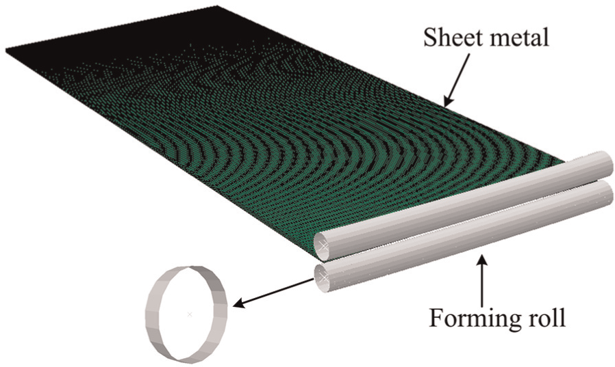
The schematic diagram of the three-dimensional rolling process is shown in Figure 1. The two-roll system is composed of a pair of matched rolls. Each roll can be adjusted and bended with small deflection independently by a series of control points on the roll, and the bending roll can rotate along its own axis under the restriction of shape-adjusting assembly. At the beginning of the forming process, the curved shape of the axis of the forming roll and the appropriate nonuniform distribution of roll gap between the two forming rolls are configured by adjusting the relative position of each control point; then, driving the two rolls to rotate around their respectively bent axes, the sheet metal is fed, the rotations of forming rolls deform and move the sheet metal by the friction between the forming rolls and the sheet metal. In this process, the nonuniform distribution of roll gap between the forming rolls makes the nonuniform elongation of the sheet metal in the longitudinal direction and the residual stress makes the sheet metal generate three-dimensional deformation. By changing the distribution pattern of roll gap, three-dimensional surface parts with different shapes can be formed through the three-dimensional rolling process.
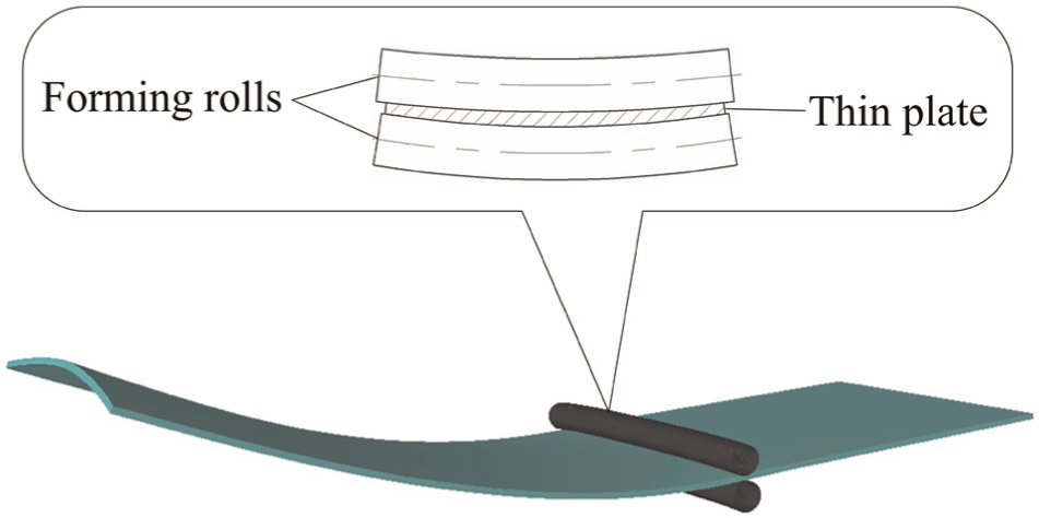
Schematic diagram of three-dimensional rolling process.
Formulation of the three-dimensional shape
As the longitudinal elongation of the sheet metal is different in the transverse direction, it is assumed that the longitudinal length after deformation at a point x in the transverse direction is Δl(x), the longitudinal strain is as follows
where εu(x) is the strain of longitudinal elongation, Δl(x) is the longitudinal length after deformation, and Δl0 is the initial longitudinal length.
In the rolling process of sheet metal, the plastic deformation of sheet metal is relatively large, so that the elastic deformation of sheet metal can be ignored. Rolling is the deformation process of volume conservation, equation (2) is obtained as follows
where εδ is the strain in thickness, εu is the longitudinal strain, and εν is the transverse strain.
As the ratio of the thickness and width of the sheet metal are usually extremely small, the width spread of the sheet metal is assumed negligible in order to simplify the analysis: εν = 0. It is considered that the distribution of strain of sheet metal is uniform in the thickness direction because of the small thickness of the sheet metal. The equation can be simplified as
where δ0 is the initial thickness of the sheet metal and δ(x) is the thickness of the forming surface.
It is assumed that the roll adjusting radius is R (as shown in Figure 2), and the value of R may be much larger than that of RT, The forming process is the same as the forming process developed by Cai and coworkers17,18 if R is equal to RT. In the Cartesian coordinates, the transverse arc length l(x) of the forming surface can be expressed as
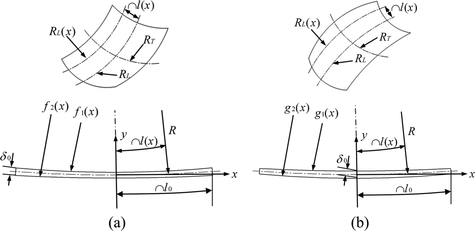
Derivation of the nonuniformly distributed roll gap: (a) convex surface and (b) saddle surface.
where l(x) is the transverse arc length of three-dimensional surface.
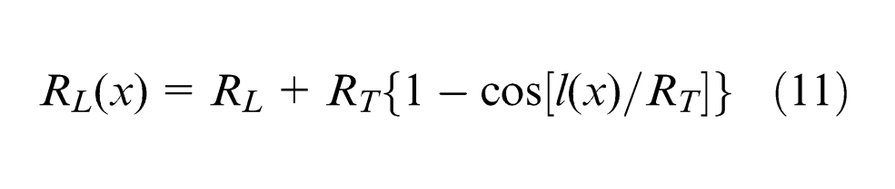
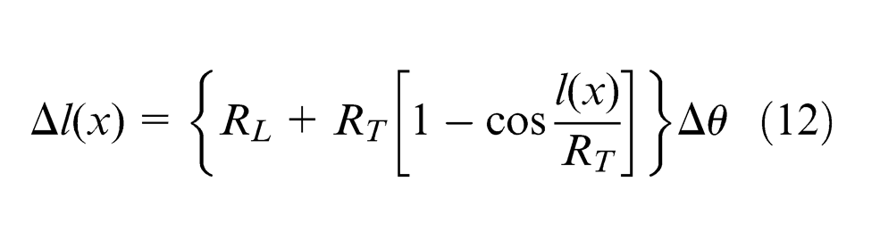
If the forming surface is a convex surface shown in Figure 2(a), the longitudinal radius of curvature RL(x) and corresponding arc length Δl(x) of the convex surface can be expressed as follows
where RL(x) is the longitudinal curvature radius at a point x, RL is the longitudinal main curvature radius of convex surface, RT is the transverse main curvature radius of convex surface and Δθ is the corresponding normal angle of the arc length of the surface.
It is assumed that the thickness of edge of the sheet metal on both sides is unchanged before and after rolling process, equation (7) is obtained as follows
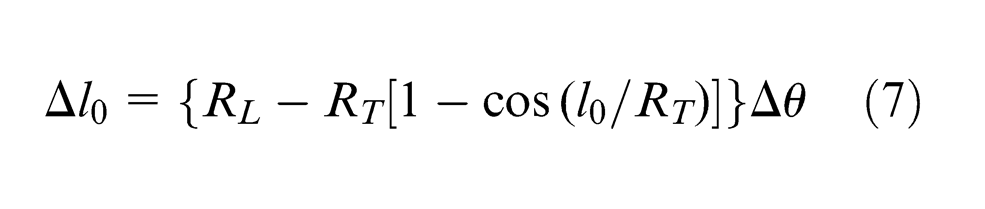
where l0 is half the width of sheet metal.
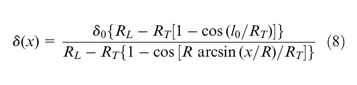
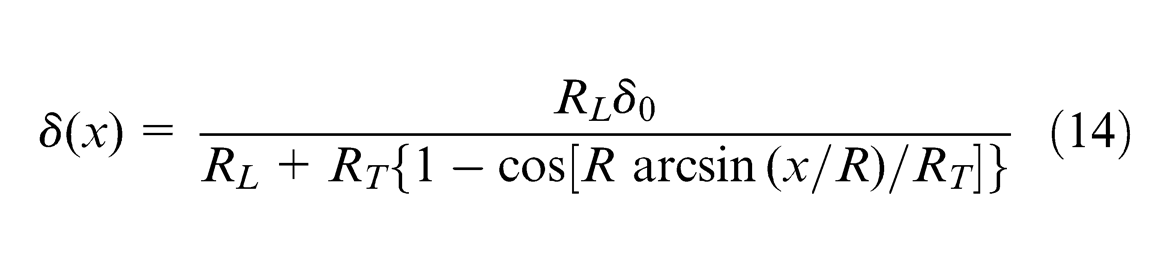
The thickness distribution of convex surface δ(x) is obtained as follows
The contour curve of the upper and lower rolls can be obtained, respectively, according to the thickness distribution of convex surface
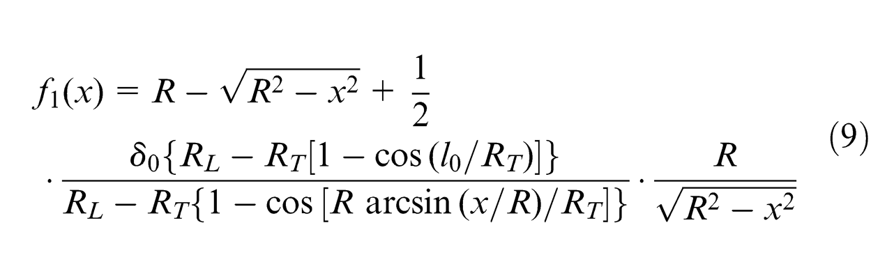
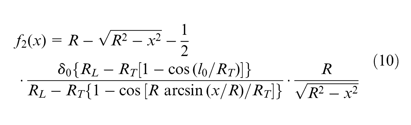
where f1(x) is the contour curve of the upper roll of convex surface and f2(x) is the contour curve of the lower roll of convex surface.
Similarly, if the forming surface is a saddle surface shown in Figure 2(b), the longitudinal radius of curvature RL(x) and corresponding arc length Δl(x) of the saddle surface could be obtained as follows
It is assumed that the middle thickness of the sheet metal in the transverse direction is unchanged before and after rolling, equation (13) is obtained as follows

The roll gap function δ(x) of saddle surface is obtained as follows
The contour curve of the upper and lower rolls can be obtained, respectively
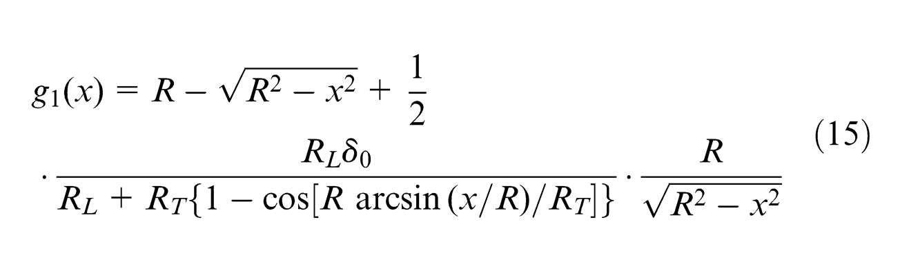

where g1(x) is the contour curve of upper roll of saddle surface and g2(x) is the contour curve of lower roll of saddle surface.
Experimental equipment for three-dimensional rolling process
Based on the three-dimensional rolling process principle, a small experimental device has been designed (as shown in Figure 3). The rolls are made of high-strength material, which can bear small bending deformation, and the outer diameter of each roll is 5 mm. Each roll is piecewise controlled by 10 control units and the maximum width of sheet metal that can be processed is 300 mm.

Experimental equipment.
Finite element model
To research three-dimensional rolling process deeply, ABAQUS/Explicit is chosen to conduct related numerical simulations. As each roll rotates around its curved axis in the experiment, the bendable roll is divided into many segments to establish the finite element model. The initial blanks are rectangular of 300 mm in length, 120 mm in width, and 2 mm in thickness, and the sheet blanks are modeled with C3D8R solid elements that are eight-node linear brick, reduced integration element. The rolls are simulated with analytical rigid bodies that do not need to be meshed in order to improve computational efficiency. The spin rate of each roll in the simulation is taken as 100 rad/s. The material of sheet metal used in the numerical simulation is low-carbon steel 08AL sheet; the relevant material parameters are the density ρ = 7800 kg/m3, elastic modulus E = 210 GPa, the yield strength σs = 135 MPa, and Poisson’s coefficient ν = 0.31. Spherical and saddle surfaces of the two types of forming processes are simulated, respectively. Figure 4 shows the finite element model of the spherical surface.
Finite element model of the spherical surface.
Results of numerical simulation and experiment
Analysis of the forming results
Figure 5 shows the simulated results and corresponding experimental results of the two types of forming processes for three-dimensional surfaces. It is observed that simulated results are well in agreement with the experimental results, which verifies the feasibility of using the simulation to guide the experiment. The simulated and corresponding experimental results of spherical and saddle surfaces on the left in Figure 5 and the corresponding plastic strain distribution of spherical and saddle surfaces on the left in Figure 6 are formed in the condition that the roll adjusting radius (R = 3600 mm) is much larger than the target transverse curvature radius of the forming surfaces (RT = 370 mm for spherical surface and RT = 420 mm for saddle surface); the simulated and corresponding experimental results of spherical and saddle surfaces on the right in Figure 5 and the corresponding plastic strain distribution of spherical and saddle surfaces on the right in Figure 6 are formed in the condition that the roll adjusting radius is equal to the target transverse curvature radius of the forming surfaces. In order to gain the same-size spherical surface or saddle surface using the two types of forming processes, the distribution of roll gap needs to be adjusted in the numerical simulation process. Therefore, the plastic strain values of the two types of forming processes are somewhat different for the same forming surface. In general, the nonuniform distribution of roll gap leads to the nonuniform plastic strain distribution of the forming parts in the transverse direction, and the plastic strain distribution of the forming part is substantially continuous in the longitudinal direction, which indicates that the forming process is stable. The plastic strain values of spherical surfaces are gradually decreasing from the middle to the edge of the sheet metal in the transverse direction; however, the plastic strain values of saddle surfaces are gradually increasing from the middle to the edge of the sheet metal in the transverse direction, which is consistent with the proposed theory.
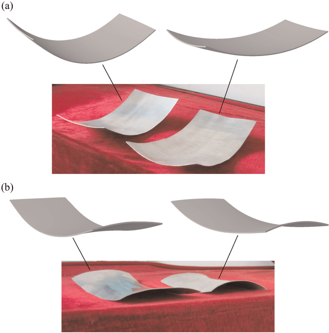
Simulated results and corresponding experimental results of two types of forming processes for three-dimensional surfaces: (a) simulated and experimental results of spherical parts and (b) simulated and experimental results of saddle parts.
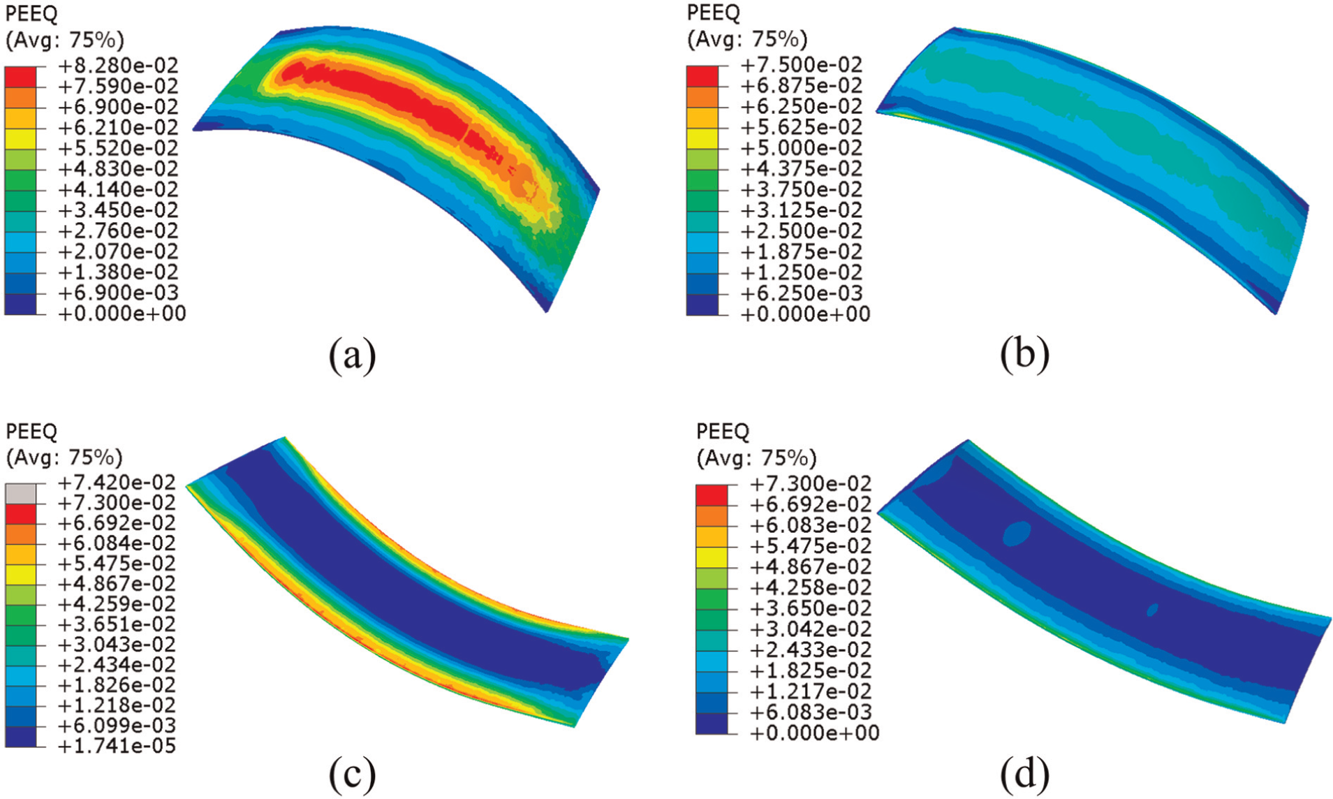
Plastic strain distribution of two types of forming processes for three-dimensional surfaces: (a) plastic strain distribution of the spherical surface (R = 3600 mm), (b) plastic strain distribution of the spherical surface (R = 370 mm), (c) plastic strain distribution of the saddle surface (R = 3600 mm), and (d) plastic strain distribution of the saddle surface (R = 420 mm).
Analysis of shape errors of simulated results
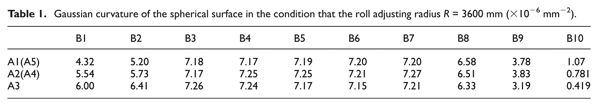
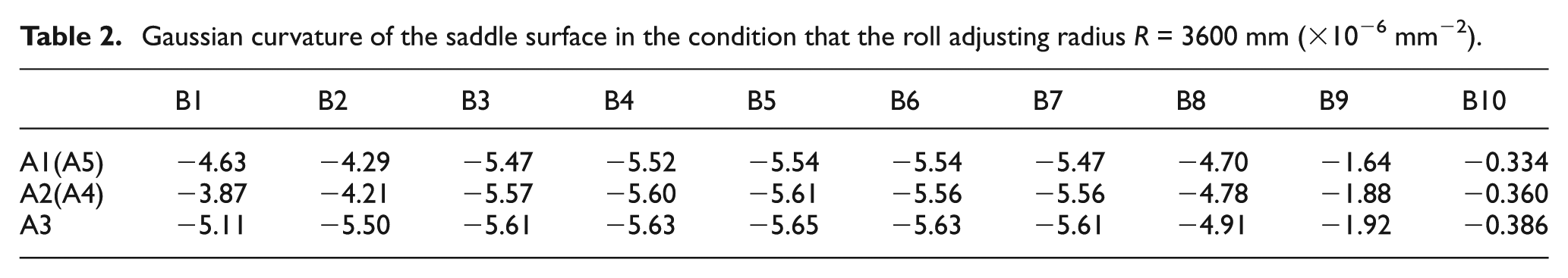
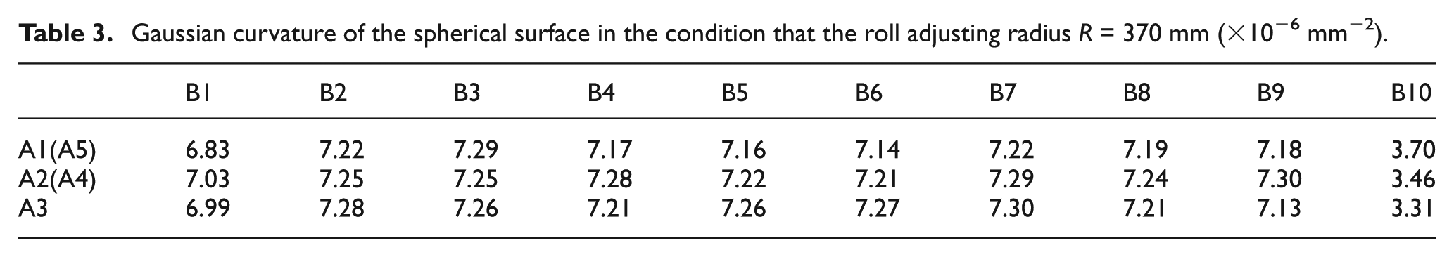
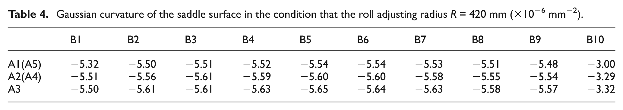
The dimensional accuracy of two types of forming processes for three-dimensional surfaces is investigated through analyzing simulation results. The roll adjusting radius is set as R = 3600 mm for one type of forming process and R = 370 mm for another forming process to obtain the spherical surface parts that the longitudinal and transverse curvature radii are RL = RT = 370 mm; the roll adjusting radius is set as R = 3600 mm for one type of forming process and R = 420 mm for another forming process to obtain the saddle surface parts that the longitudinal and transverse curvature radii are RL = RT = 420 mm. As Gaussian curvature determines the local shape of a point on a surface, the change of surface shape can be reflected by comparing the Gauss curvature of a point and the near point. It is assumed that kmax and kmin are the two principal curvatures of a point on a surface. The Gaussian curvature K of the point can be expressed as

The Gauss curvature is greater than zero for forming convex-shaped surface and less than zero for forming saddle-shaped surface. The Gauss curvature of all points on the spherical surfaces of two types of forming processes should be equal and the theoretical value is 7.30 × 10⁻⁶ mm−2 in the condition that the longitudinal and transverse target curvature radii are RL = RT = 370 mm; the Gauss curvature of saddle surfaces using the two types of forming processes is gradually decreasing from the middle to the edge of the sheet metal in the transverse direction, and the theoretical value is from −5.67 × 10⁻⁶ to −5.55 × 10⁻⁶ mm−2 in the condition that the longitudinal and transverse target curvature radii are RL = RT = 420 mm. The three-dimensional parts of two types of forming processes are divided into many same-size regions, the dimension of each region of the forming surface is 24 mm in the transverse direction and 30 mm in the longitudinal direction, and the Gaussian curvature of central point represents the surface shape of corresponding region, respectively, as shown in Figure 7. The measured results are listed in Table 1 for the spherical surface part and Table 2 for the saddle surface part in the condition that the roll adjusting radius is set as R = 3600 mm for one type of forming process; in another forming process, the results are listed in Table 3 for the spherical surface part in the condition that the roll adjusting radius is set as R = 370 mm and Table 4 for the saddle surface part in the condition that the roll adjusting radius is set as R = 420 mm. In the tables, the data of A1 row are equal to that of A5 row and the data of A2 row are equal to that of A4 row as the forming parts are symmetric about A3 row. The Gaussian curvature of forming parts between the B3 and B7 columns is close to the Gaussian curvatures of the targets that the roll adjusting radius is set as R = 3600 mm for one type of forming process, as shown in Tables 1 and 2; the maximum relative deviation of the Gaussian curvature is 2.05% for the spherical part and 1.44% for the saddle part between the B3 and B7 columns of the forming parts; the Gaussian curvature of forming parts between the B2 and B9 columns is close to the Gaussian curvature of the targets that the roll adjusting radius is the same as the target transverse curvature radius of the forming surface parts for another type of forming process, as shown in Tables 3 and 4, the maximum relative deviation of the Gaussian curvature is 2.33% for the spherical part and 1.76% for the saddle part between the B2 and B9 columns of the forming parts. The effective forming regions of the forming parts are different though the comparison of the data results of two types of forming processes, the length of effective forming region (between the B2 and B9 columns in Figure 7(b) and (d)) of the forming process that the roll adjusting radius is the same as the target transverse curvature radius of the forming surface parts (between the B2 and B9 columns in Figure 7(a) and (d)) of another forming process that the roll adjusting radius is much larger than the target transverse curvature radius of the forming surface parts (between the B3 and B7 columns in Figure 7(a) and 7(c)).
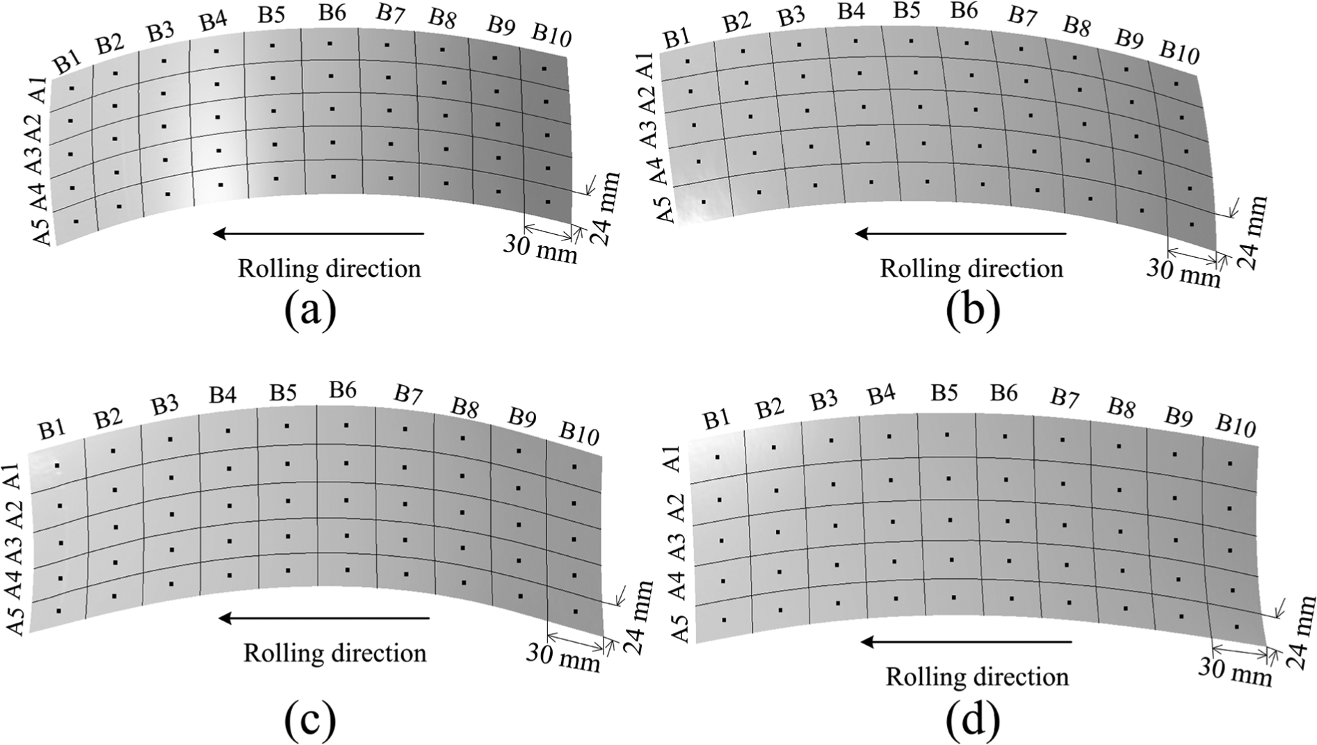
Division of two types of three-dimensional surface parts of simulated results: (a) spherical surface (R = 3600 mm), (b) spherical surface (R = 370 mm), (c) saddle surface (R = 3600 mm), and (d) saddle surface (R = 420 mm).
Gaussian curvature of the spherical surface in the condition that the roll adjusting radius R = 3600 mm (×10−6 mm−2).
Gaussian curvature of the saddle surface in the condition that the roll adjusting radius R = 3600 mm (×10−6 mm−2).
Gaussian curvature of the spherical surface in the condition that the roll adjusting radius R = 370 mm (×10−6 mm−2).
Gaussian curvature of the saddle surface in the condition that the roll adjusting radius R = 420 mm (×10−6 mm−2).
The difference between the data results of two types of forming processes is analyzed by comparing the corresponding spherical surface parts. At the beginning of forming process, the difference value of the longitudinal tensile strain between the upper and lower surfaces of the sheet metal for one type of forming process that the roll adjusting radius is the same as the target transverse curvature radius of spherical surface is greater than that of another type of forming process that the roll adjusting radius is much larger than the target transverse curvature radius of spherical surface (as shown in Figure 8). The difference value of the longitudinal tensile strain between the upper and lower surfaces of the sheet metal is greater; the target shape is gained more easily. Thus, the shape of head region is closer to the target shape if the roll adjusting radius is the same as the target transverse curvature radius of the forming surface parts. The metal will flow to the tail due to the small resistance of the trail region near the end of forming process, and the difference value of the longitudinal tensile strain between the upper and lower surfaces of the sheet metal decreases gradually, which makes the shape less than the target shape in the trail region, as shown in Figure 9. The forming process that the roll adjusting radius is much larger than the target transverse curvature radius of the forming surface parts has relatively larger shape error in the tail region as the difference value of the longitudinal tensile strain between the upper and lower surfaces of the sheet metal is almost entirely provided by the residual stress that is caused by the nonuniform elongation of sheet metal in the longitudinal direction; however, the difference value of the longitudinal tensile strain between the upper and lower surfaces of the sheet metal for another forming process that the roll adjusting radius is the same as the target transverse curvature radius of the forming surface parts is provided by the relatively large bending deformation of the rolls as well as the residual stress that is caused by the nonuniform elongation of sheet metal in the longitudinal direction.
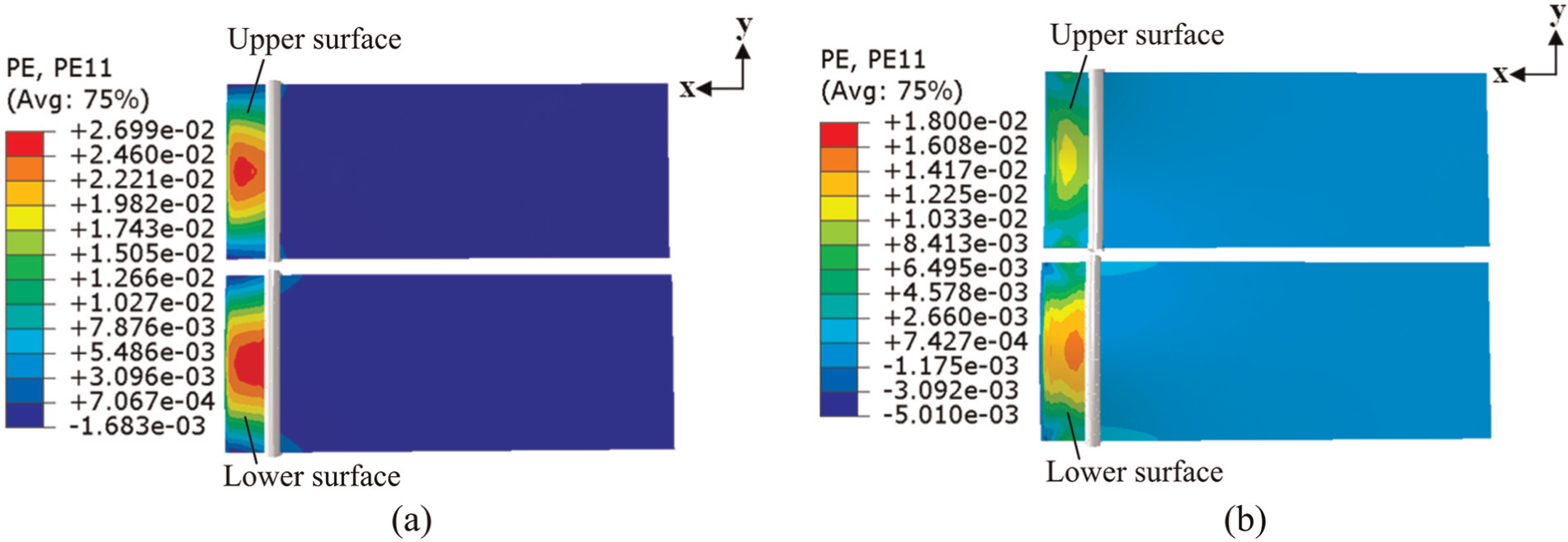
Difference value of the longitudinal tensile strain between the upper and lower surfaces of spherical parts at the beginning of the forming process: (a) spherical part (R = 3600 mm) and (b) spherical part (R = 370 mm).
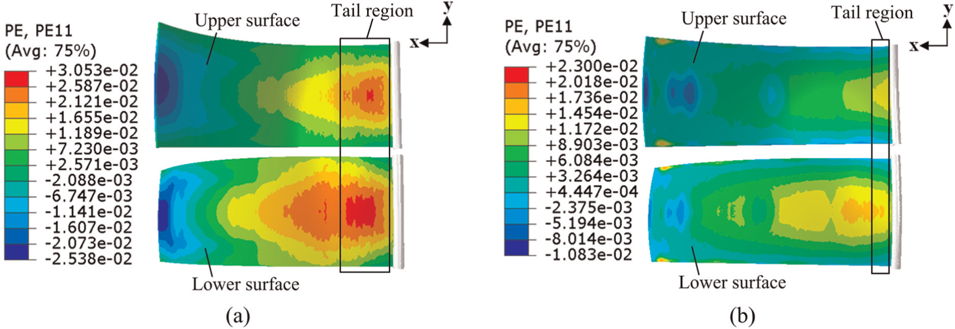
Difference value of the longitudinal tensile strain between the upper and lower surfaces of spherical parts at the end of the forming process: (a) spherical part (R = 3600 mm) and (b) spherical part (R = 370 mm).
Conclusion
Three-dimensional rolling is a novel continuous forming technology for three-dimensional surface parts, which combines the rolling process with multi-point forming technology. The work reported here is focused on the difference between the two types of forming processes that the bending deformation of the forming rolls is different for the same-size forming surface part. Based on the investigation, the following conclusions can be drawn:
The length of effective forming region of the forming part of the forming process that the roll adjusting radius is the same as the target transverse curvature radius of the forming parts is longer than that of another forming process that the roll adjusting radius is much larger than the target transverse curvature radius of the forming parts.
The difference value of the longitudinal tensile strain between the upper and lower surfaces of the sheet metal is almost entirely provided by the residual stress that is caused by the nonuniform elongation of sheet metal for the forming process that the roll adjusting radius is much larger than the target transverse curvature radius of the forming parts; however, the difference value of another forming process that the roll adjusting radius is the same as the target transverse curvature radius of the forming parts is provided by the relatively large bending deformation of the rolls as well as the residual stress that is caused by the nonuniform elongation of sheet metal.
Research shows that the forming results are relatively well if the roll adjusting radius is the same as the target transverse curvature radius of the surface parts. Therefore, the bending deformation of forming rolls is as large as possible in the condition that the rolls can withstand and are able to rotate around their respectively bent axes in order to form three-dimensional surface parts with relatively small transverse curvature radius.
Footnotes
Acknowledgements
The authors would like to acknowledge the computer hardware support provided by High Performance Computing Center of Jilin University, China.
Declaration of conflicting interests
The authors declare that there is no conflict of interest.
Funding
Financial assistance for this study was provided by the National Natural Science Foundation of China (no. 51275202).