
Abstract
To improve the machining accuracy and production efficiency of face gears, this article presents a generating milling method for the spur face gear using a five-axis computer numerical control milling machine and proposes a milling principle of the spur face gear using a milling cutter. Based on the milling principle and theory of gearing, a mathematical model of the spur face gear milling cutter is established, and the design parameters of the cutter are determined. Considering the requirements of machine motion during the face gear milling process, a five-axis computer numerical control milling machine is developed to produce the face gear. Based on the structure of the milling machine, a mathematical model of the spur face gear is established, and a milling method is proposed. The spur face gear milling cutter is manufactured, and the face gear milling experiments are conducted on the self-developed milling machine. The measurement results of the tooth surface deviations indicate that the maximum deviation is 22.6 µm, and that the machined spur face gear accuracy can meet the requirements of roughing. The experimental results verify the validity of the proposed generating milling method and demonstrate that the generating milling method is an effective approach to improve the accuracy and efficiency of the spur face gear.
Keywords
Introduction
Gear drives are efficient precision mechanisms in industry that transmit power and motion. Among the various gears, spur face gears are used for power transmission in a growing number of applications. The advantages of spur face gears include (1) low sensitivity of bearing contact caused by misalignments, (2) reduced noise due to the low level of transmission errors, (3) possibility of torque-split and weight reduction, and (4) favourable tolerance of assembly errors compared to spiral bevel gears. Due to these advantages, face gears also have potential applications in many other fields, such as machine tools, automobiles, helicopters, and gearboxes of solar power systems.
To date, many studies have been conducted to investigate face gear processing technology. The face gear processing method includes roughing and finishing. The former includes shaping, milling, and hobbing, whereas the latter includes grinding. The roughing process is mainly used to remove material; thus, an efficient roughing method is an important factor in improving production efficiency. Litvin et al. 1 contributed to the development of face gear theory by establishing a theoretical model of spur face gears generated by a shaper, proposing a design method that avoids tooth pointing and undercutting and demonstrating that the face gear could be applied in power transmission through experiments. In terms of the roughing process, Litvin et al. 2 analysed the geometry of the spur face gear generated by a worm cutter, presented an analytical method to determine the worm thread surface of the cutter, and proposed that a face gear generated by a cutter with a rounded top edge offered better bending strength. Additionally, Litvin et al. 3 improved the tooth profile of the spur face gear to avoid edge contact, proposed a method to design a worm cutter, and obtained a worm surface free of singularities. Litvin et al. 4 subsequently proposed a design method for the helical face gear and established a mathematical model of the hobbing cutter used to produce the helical face gear. Wu and Wang 5 studied the spur face gear hobbing principle, developed a face gear hobbing simulation program and designed a hobbing cutter to perform the hobbing experiment. However, the machining accuracy and processing cost of the face gear are unsatisfactory due to the complexity of the hobbing cutter profile. Cui et al. 6 proposed a method to design the arc-tooth face gear based on the theory of gearing and performed machining experiments using Gleason cutter discs. However, this method cannot be applied to produce spur face gears due to cutter shape limitations. Yang and Tang 7 investigated the plunge milling method to produce spur face gears, calculated the processing parameters of the plunge milling cutter, and simulated the plunge milling process. However, the plunge milling method suffers from disadvantages, such as large machining errors at the tooth root and long machining time, due to the existence of the tooth root fillet and dimension limitations of the plunge milling cutter.
To improve the machining accuracy and production efficiency, many researchers have investigated the processing technology for bevel and spur gears.8,9 Gear milling is commonly used in gear processing. Suh et al. 10 studied the tool path planning algorithm for the spiral bevel gear machining process and manufactured the gear on a three-axis milling machine. Andrei et al. 11 presented a method for producing a curved face width gear, analysed the kinematics of the cutting tool and gear, and manufactured the gear using a spiral bevel gear milling machine. Ozel et al. 12 studied the manufacturing method of the straight bevel gear, deduced the manufacturing equation of the tooth surface, developed a macro program for milling a straight bevel gear, and manufactured the gear using an end mill. However, this method is less efficient than the generating method. Fan 13 presented a generalised tooth surface generation model of the spiral bevel gear manufactured by the face-milling or face-hobbing process and analysed the kinematical features of these two processes. Furthermore, Fan et al. 14 studied the tooth surface error correction method of the hypoid gear manufactured by the face-milling process, established the relationships between tooth surface errors and universal motion coefficients, and realised error correction on a hypoid generating machine. However, the proposed processes cannot be applied to produce a face gear due to the difference in tooth profiles. Safavi et al. 15 proposed a milling method for the spiral bevel gear based on the three-axis milling machine, studied the geometrical modelling and process planning of the gear, and concluded that this method could be modified to produce other types of bevel gears. However, the proposed method cannot be used to produce a face gear due to the machine motion limitations. Ozel16,17 proposed the spur gear cutting method on a computer numerical control (CNC) vertical milling machine, developed a computer-aided manufacturing (CAM) program for manufacturing stand and non-stand spur gears, and noted that the machining time increased with the modules and number of teeth. However, the problem with this method is that it is difficult to produce small module gears, and that the machining time is longer than that of the generating method. Alves et al. 18 proposed an analytical model for the spiral bevel gear with tooth modification, performed the milling experiment on a five-axis machine centre by transferring the model into CAM software, and reported that this type of machine could process any type of tooth surface. However, it would take a relatively long time to manufacture the spiral bevel gear compared to manufacturing by Gleason or Klingelnberg machines. The Gleason machine can produce face-milled or face-hobbed gears. The tooth depths change from the toe to the heel. The Kingelberg machine can produce face-hobbed gears in which gear teeth have a constant height. Although the tooth depths and tooth profiles of two types of the spiral bevel gears are different, the Gleason and Kingelberg machines each adopts the continuous generating cutting method with high production efficiency. Xie 19 proposed a milling cutter geometrical model for the face-milled spiral bevel gear and optimised the cutting edges and cutting angles to achieve improved surface quality and accuracy. Deng et al. 20 proposed a CNC face-milling method for the spiral bevel gear using a disc cutter with concave end, designed the cutter structure, calculated the tilt and yaw angle of the cutter, and demonstrated an improved cutting strip width and production efficiency. To improve machining accuracy, Fratila and Radu 21 investigated the thermal expansion and thermoelastic strain of the teeth during the gear milling process, observed that cooling and lubrication could reduce machining accuracy, and concluded that the displacement along the radial direction of the tooth was significant. Brinksmeier et al. 22 studied the influence of cutting parameters on distortion and residual stress distribution of the tooth surface and concluded that the feed speed had a significant effect on distortion. Their work provides a useful guide to choose the cutting parameters of the face gear.
However, the processing technology must be investigated to produce a spur face gear with high accuracy and efficiency because the tooth profile of the spur face gear is significantly different compared to bevel and spur gears. This article proposes a novel generating milling method for the spur face gear to improve the machining accuracy and production efficiency. First, the milling principle of the spur face gear is proposed. Based on the milling principle, a mathematical model of the spur face gear milling cutter is established, and the cutter parameters are designed. Then, a five-axis face gear milling machine is designed and developed considering the requirements of machine motion during face gear milling process. The mathematical model of the spur face gear manufactured by the milling cutter is established based on the structure of the milling machine. Finally, the milling cutter is manufactured, and the spur face gear milling experiments are performed. The validity of the proposed generating milling method for the spur face gear is experimentally verified.
Milling principle of the spur face gear
The tooth surface of the spur face gear is generated by the shaper; thus, by simulating the shaper motion, the milling cutter can be applied to produce the face gear. The milling principle of the spur face gear is illustrated in Figure 1. The imaginary shaper meshes with the face gear and simultaneously meshes with the milling cutter; thus, the milling cutter can mesh correctly with the face gear. In the milling process, the face gear rotates around its own axis yf with an angular velocity ωf, and the milling cutter rotates around its own axis zm with an angular velocity ωm and also swings around the virtual axis xs of the imaginary shaper. The relationship between the swing velocity ωs of the milling cutter and the angular velocity ωf of the spur face gear can be estimated by equation (1)

where Nf and Ns are the number of teeth in the spur face gear and imaginary shaper, respectively.
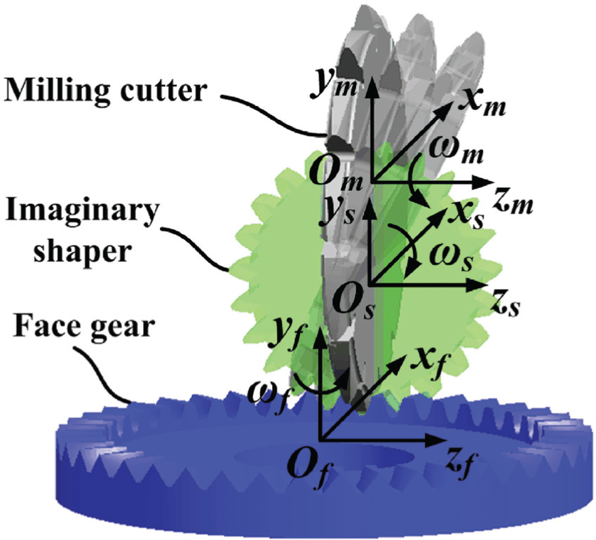
Illustration of the spur face gear milling process.
In the face gear milling process, the generating motions are the swing rotation of the milling cutter around the virtual axis of the imaginary shaper and the rotation of the face gear around its own axis. The feed motions include the rectilinear motions of the milling cutter along the tooth width and along the tooth depth. When one tooth is machined completely, the face gear performs an indexing motion along its own axis and proceeds to milling the next tooth. The process circulates until all teeth are machined.
Design of the spur face gear milling cutter
Rack cutter profile
The tooth surface of the spur face gear milling cutter is determined by the imaginary shaper. The rack cutter profile used to generate the imaginary shaper is shown in Figure 2.
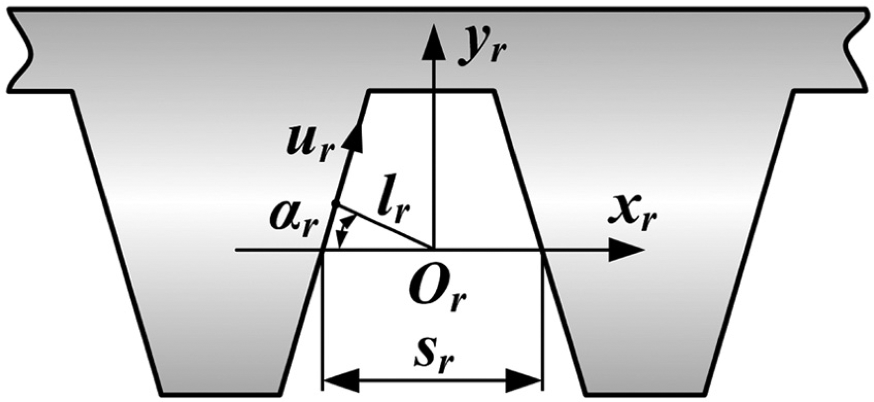
Schematic of the rack cutter.
In Figure 2, ur is the surface parameter of the rack cutter, αr is the transversal pressure angle, sr = πm/2 represents the space width, m is the module, and lr = πm cos αr/4 represents the vertical distance from the origin of coordinate Or to the rack cutter profile.
The tooth profile of the rack cutter is represented in coordinate system σr (xr, yr, zr) as
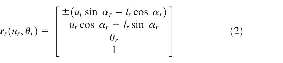
where the sign ‘±’ represents the left and right profiles of the rack cutter, and θr is the surface parameter as measured along axis zr.
The unit normal vector
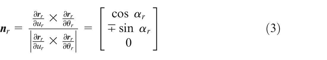
Generated tooth surface of the imaginary shaper
The imaginary shaper surface is generated by the rack cutter. The coordinate systems for generating the imaginary shaper are shown in Figure 3. The movable coordinate systems σr (xr, yr, zr) and σs (xs, ys, zs) are attached to the rack cutter and imaginary shaper, respectively. The fixed coordinate system σn (xn, yn, zn) is attached to the frame of the machine. In Figure 3, the circle represents the pitch circle of the imaginary shaper, the axis xr represents the pitch line of the rack cutter, rps is the pitch radius of the imaginary shaper, ϕs is the rotation angle of the imaginary shaper, and rpsϕs is the movement of the rack cutter. The parameters rpsϕs and ϕs determine the relative translational and rotational motions between the rack cutter and the imaginary shaper, respectively.
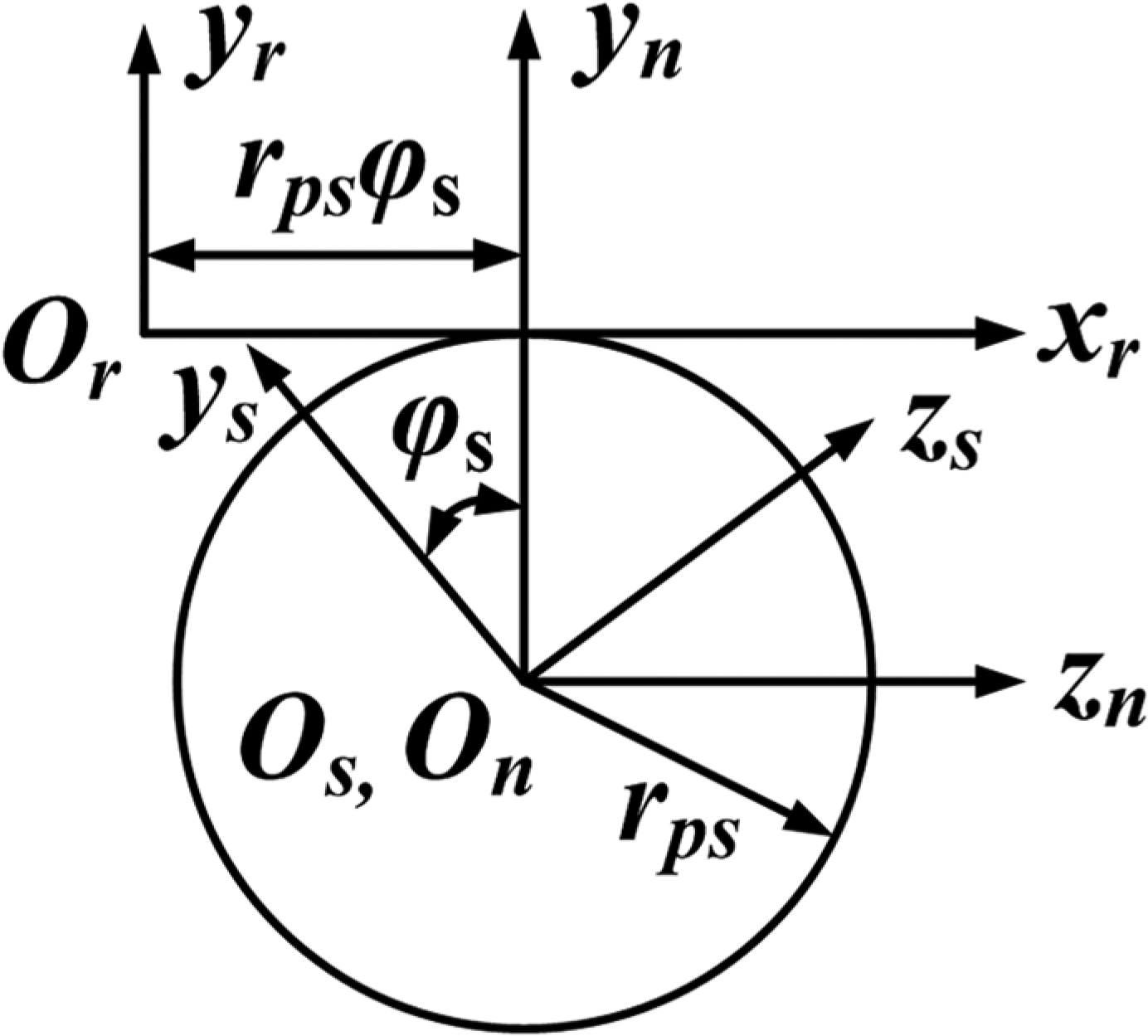
Coordinate systems for generating the imaginary shaper.
In the coordinate system σs (xs, ys, zs), the tooth surface of the imaginary shaper is represented as

where
The equation of meshing

Thus, the tooth surface of the imaginary shaper can be expressed as

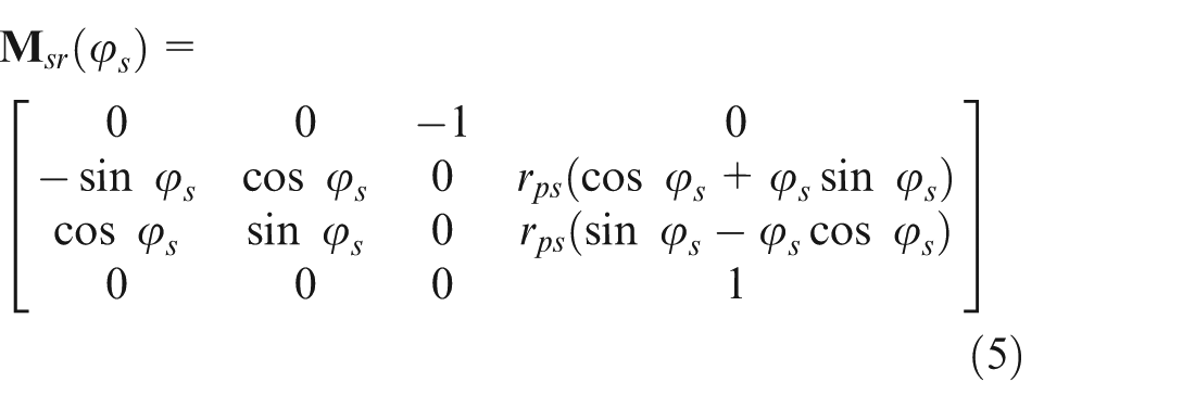
The unit normal vector

where the matrix
Tooth profile of the milling cutter
The milling cutter is used to produce the spur face gear; its profile is determined by rotating the generating line around axis zm, as shown in Figure 4. The generating line is the tooth profile of the imaginary shaper when xs = 0, namely, θr = 0 in equation (7). In Figure 4, the movable coordinate system σm (xm, ym, zm) is attached to the milling cutter, and the fixed coordinate system σm0 (xm0, ym0, zm0) is attached to the machine frame. The parameter Em = rmc − rps represents the centre distance between the milling cutter and imaginary shaper, and rmc represents the radius of the milling cutter.
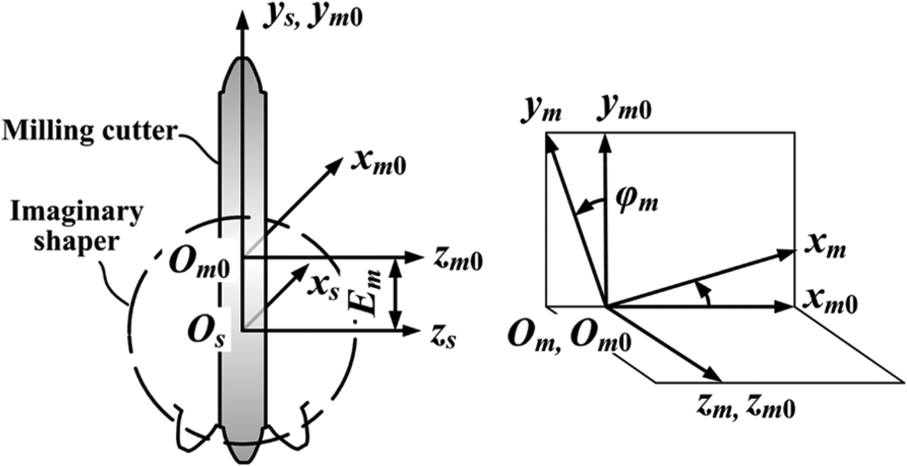
Coordinate systems for generating the milling cutter profile.
To ensure that the surface parameter of the rack cutter θr = 0, the surface equation of the milling cutter is expressed in coordinate system σm (xm, ym, zm) as

where ϕm represents the surface parameter of the milling cutter, and
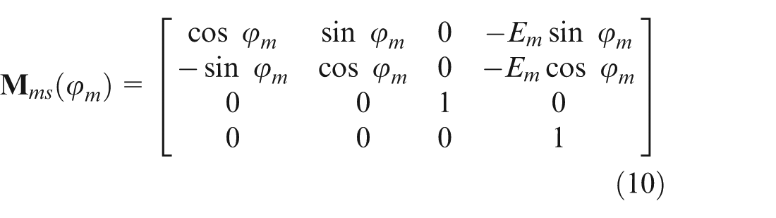
The unit normal vector of the milling cutter is expressed as

where the matrix
Parameters of the spur face gear milling cutter
Width of the milling cutter
According to the Handbook of Metal Cutting Tool Design, 23 the recommended width of the milling cutter Bm equals the width of the tooth root plus 1–3 mm. Thus, in this work, the width Bm equals the width of the tooth root plus 2 mm.
Rake angle
According to the Handbook of Metal Cutting Tool Design, 23 when the rake angle of the milling cutter γ = 0°, the tooth profile of rake face is consistent with the axial profile of imaginary shaper, which contributes to the simplification of the process of milling cutter design, manufacturing, detection, and resharpening. Thus, the rake angle γ = 0° is selected.
Parameter of relieving
The parameter of relieving Km is determined by the outer diameter of the milling cutter Dm, the number of gashes zm, and the clearance angle αa at the top cutting edge. The parameter Km, as shown in Figure 5, is calculated by
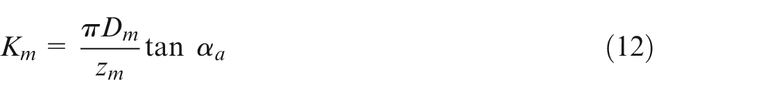
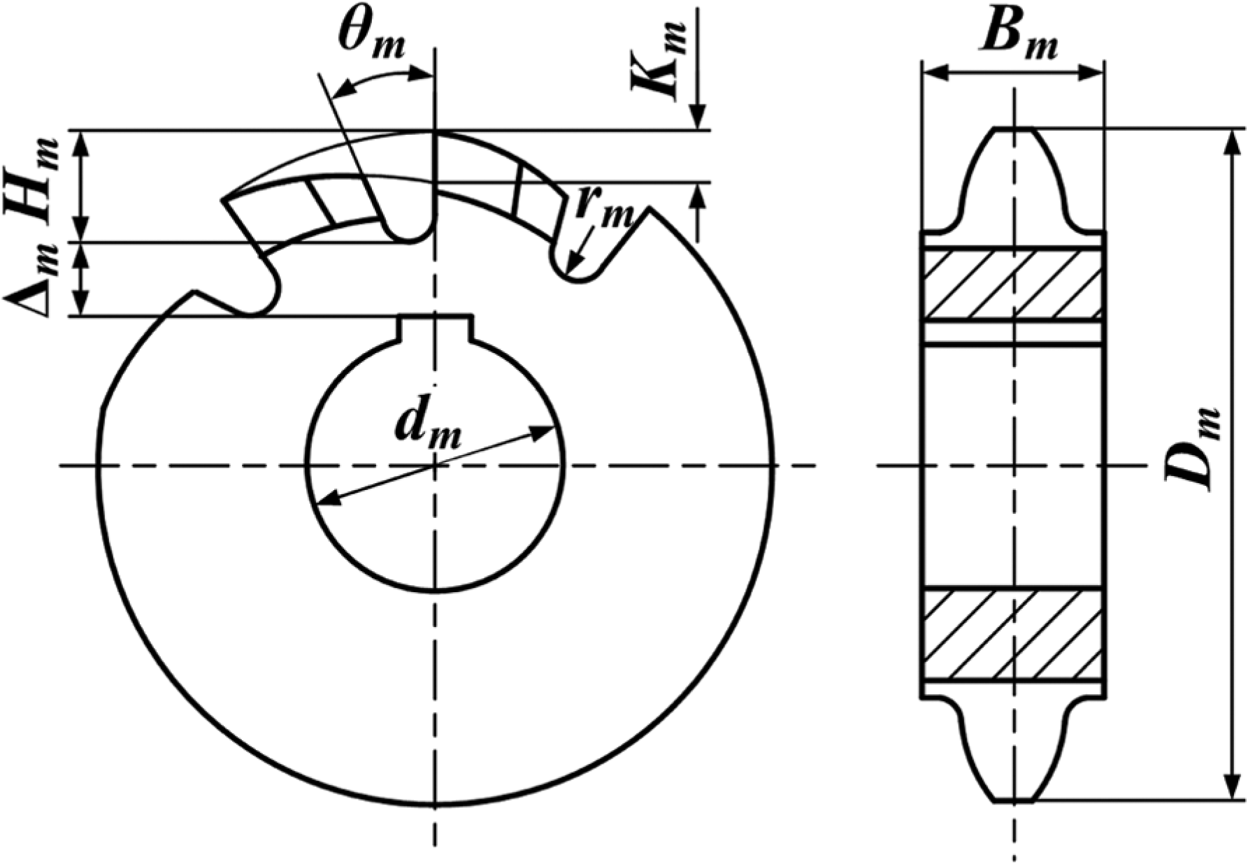
Parameters of the spur face gear milling cutter.
According to the Handbook of Metal Cutting Tool Design, 23 to ensure that the clearance angle at the lateral cutting edge is not less than 1°20′, the value of clearance angle αa is recommended to fall in the range of 10°–15°.
Parameters of the gash
The gash depth Hm is determined by the tooth depth of the milling cutter hm and the parameter of relieving Km and is calculated as follows

Flutes are classified as either straight or broken line. The former facilitates manufacturing, whereas the latter is helpful in improving the strength of the milling cutter. When the module of the milling cutter is less than 6 mm, the straight flute is selected. Otherwise, the broken-line flute is selected. 23
The root radius of the gash rm is calculated by the following formula
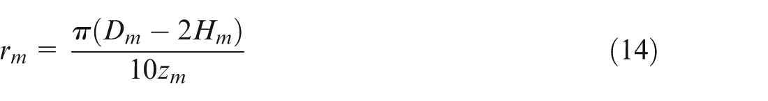
The gash angle θm is chosen to be 18°–25° by referring to the design specifications of the spur gear milling cutter. 23
To ensure the strength of the milling cutter, the distance Δm between the keyway and the root of the gash should satisfy the following formula

where dm is the bore diameter of the milling cutter.
Based on the above analysis, the flowchart of the design of the spur face gear milling cutter is illustrated in Figure 6.
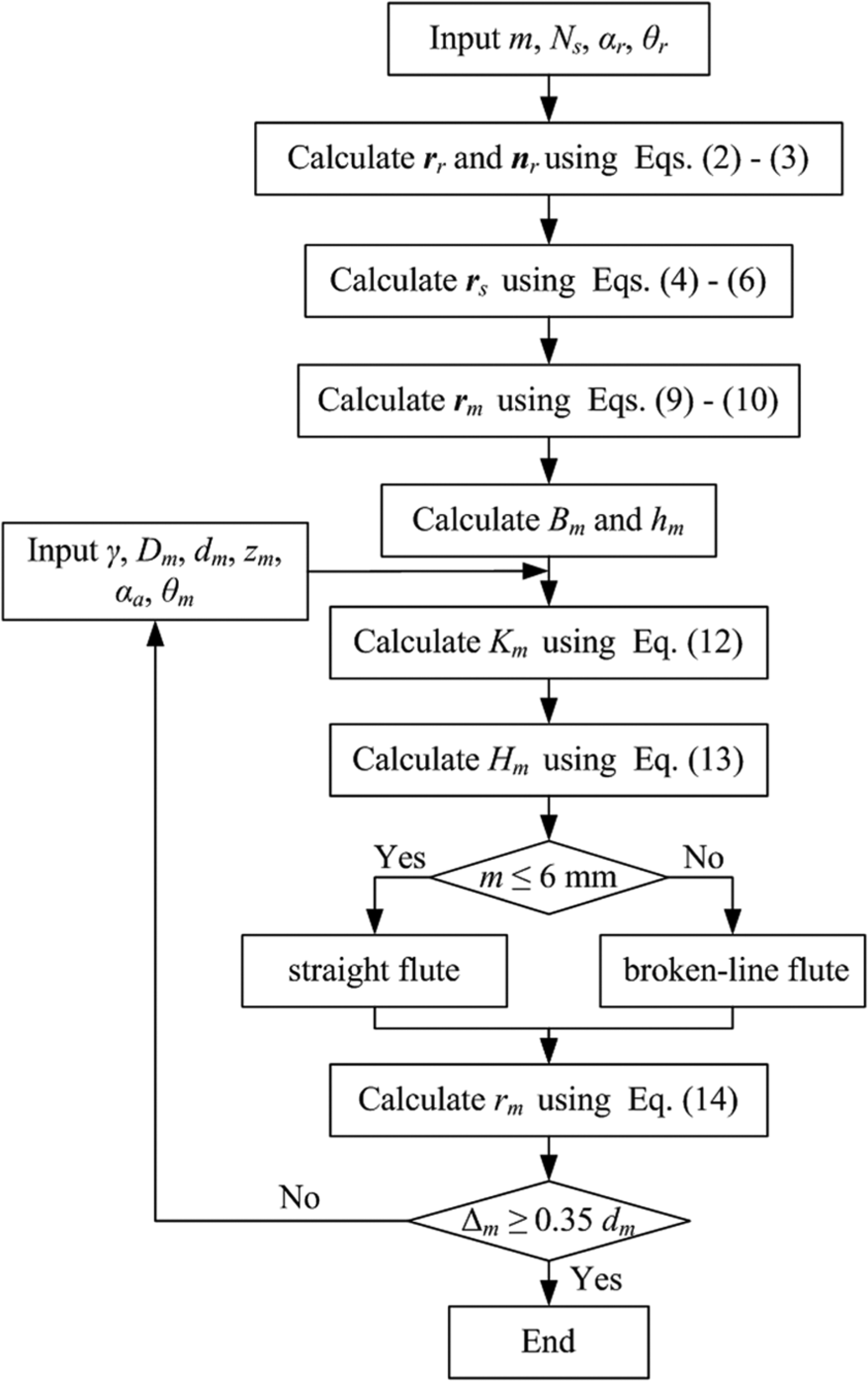
Flowchart of the design of the spur face gear milling cutter.
Milling method for the spur face gear based on the five-axis face gear milling machine
Structure of the face gear milling machine
The five-axis face gear milling machine is designed and developed in accordance with the requirements of machine motion during the spur face gear milling process. The structure of the milling machine is shown in Figure 7. The face gear milling machine has five numerically closed-loop controlled axes: three rectilinear axes (X, Y, Z) and two rotational axes (A, B). The five axes are directly driven by servo motors and can implement the prescribed motions. The radial rectilinear motion Dx is used to create the tooth surface along the tooth width. The axial rectilinear motion Dy is applied to create the tooth depth and allow additional motion between the milling cutter and the face gear. The tangential rectilinear motion Dz allows additional motion between the milling cutter and face gear.
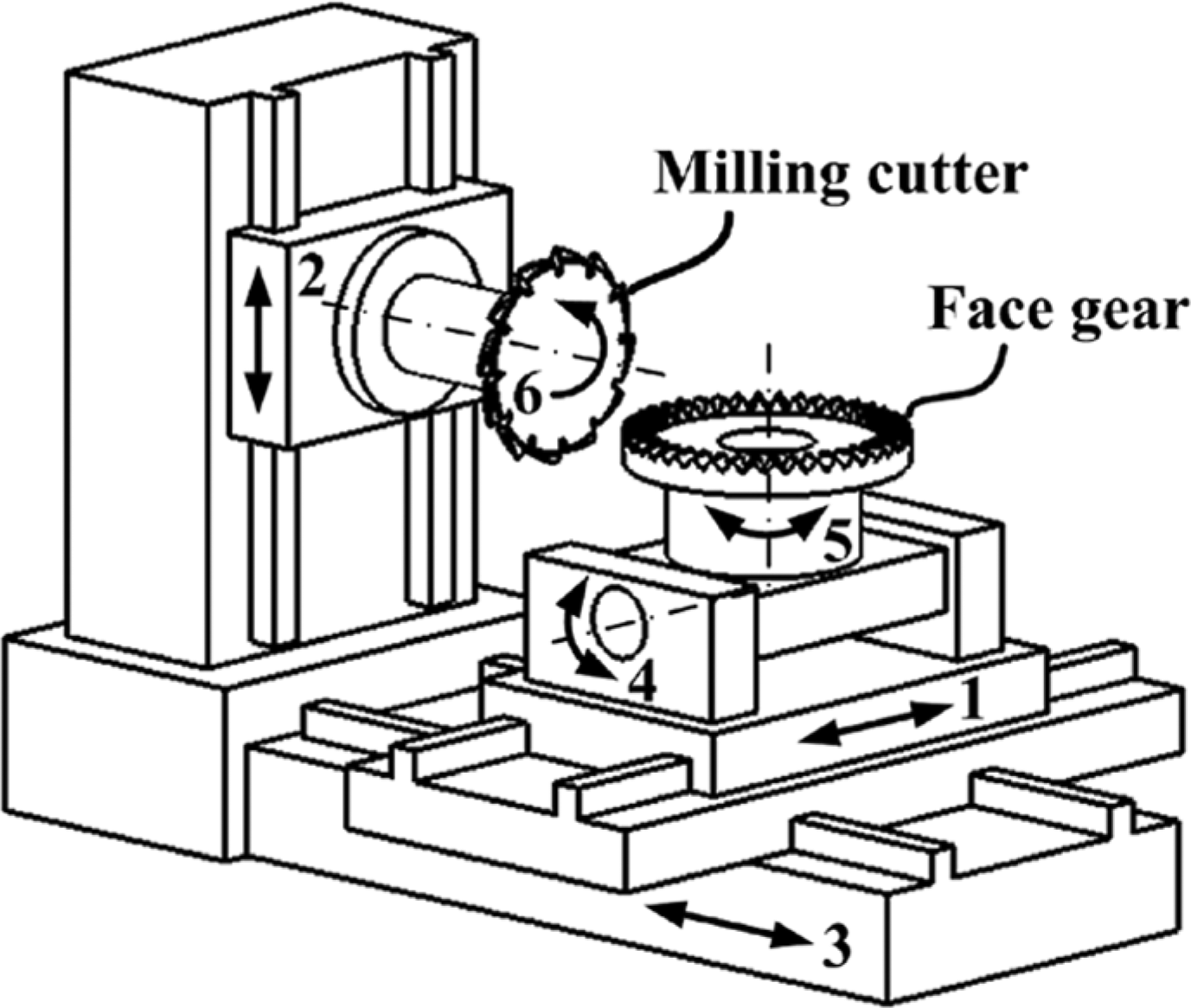
Structure of the five-axis face gear milling machine. 1. Radial slide (X, Dx), 2. axial slide (Y, Dy), 3. tangential slide (Z, Dz), 4. workpiece swivel axis (A, ϕs), 5. workpiece spindle (B, ϕf), and 6. cutter spindle.
During the face gear milling process, the rectilinear motion components Dy and Dz are coupled with the rotational motion ϕf and ϕs to produce the generating motion between the face gear and milling cutter. Moreover, ϕf and ϕs satisfy the following equation

Milling method for the spur face gear based on the five-axis milling machine
The initial position of the milling cutter is position 1, and the rotation centre of the milling cutter is O. According to the generating milling principle presented in section ‘Milling principle of the spur face gear’, the milling cutter swings around the centre of the imaginary shaper Os from positions 1 to 2 with an angular velocity ωs, and the swivel angle is ϕs. The motion path of the rotation centre of the milling cutter is arc OO′, as indicated by the red arc in Figure 8.
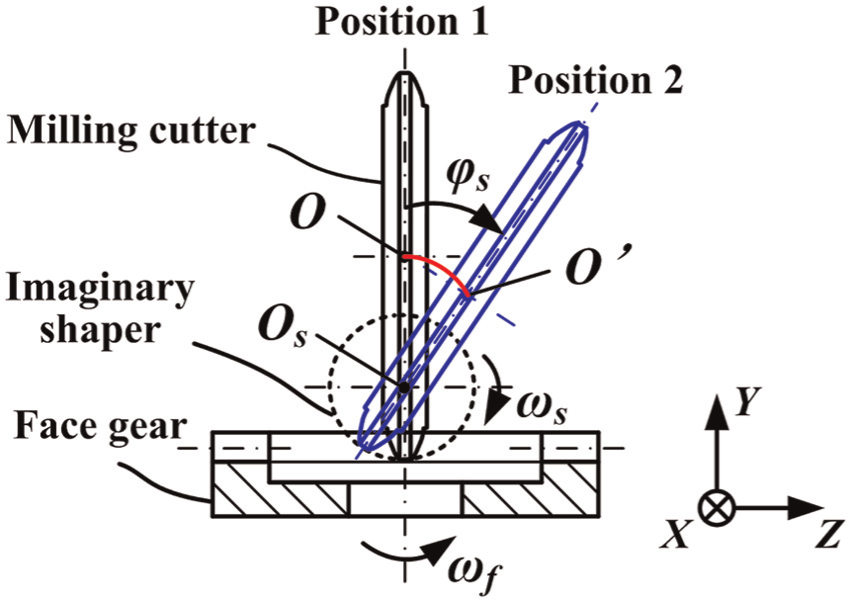
Schematic of the face gear milling process.
Due to the limitations of the face gear milling machine, the milling cutter cannot swing (see Figure 7). To achieve the relative motions between the milling cutter and face gear, the face gear must swing around the centre of the imaginary shaper Os. As a result, the face gear rotates from positions 1 to 2, as illustrated in Figure 9. Based on the structure of the milling machine, the face gear cannot directly swing around the centre of the imaginary shaper Os to reach position 2. However, it can rotate around the centre of the workpiece swivel axis Ow. Thus, the face gear first rotates around Ow to position 3 and then translates from positions 3 to 2. The rotation angle of the face gear equals the swivel angle of the milling cutter, and its value is ϕs. The translational motions of the face gear are achieved by the linkage control of the Y axis and Z axis of the milling machine, and the motion path of the face gear is line G′G as illustrated in Figure 9. During the translational motion process, the face gear also rotates around its own axis with angular velocity ωf.
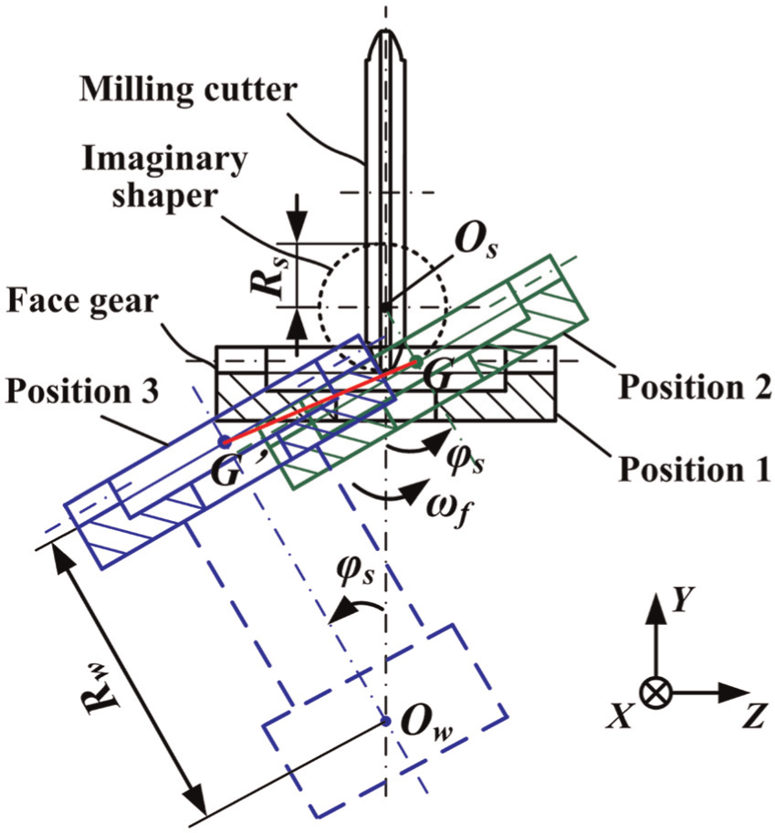
Milling method for the face gear based on the five-axis milling machine.
In Figure 9, the rectilinear motion distance of the face gear along the Y axis is

The rectilinear motion distance of the face gear along the Z axis is

where Rs is the radius of the imaginary shaper and Rw refers to the distance between the centre of the workpiece swivel axis Ow and the tooth root of the face gear.
To produce the entire tooth surface, the milling cutter is required to move along the X axis, and the motion distance Dx equals the tooth width of the face gear. Thus, the face gear can be manufactured by controlling three rectilinear motions (Dx, Dy, Dz) and two rotational motions (ϕf, ϕs).
Tooth surface equation of the spur face gear
Based on the five-axis face gear milling machine, the coordinate systems for milling the spur face gear are illustrated in Figure 10. Coordinate systems σm (xm, ym, zm) and σf (xf, yf, zf) are attached to the milling cutter and spur face gear, respectively; σa (xa, ya, za), σb (xb, yb, zb), and σc (xc, yc, zc) are attached to the axial, tangential, and radial slide, respectively; σd (xd, yd, zd) is attached to the workpiece swivel axis; and σe (xe, ye, ze) is attached to the frame of machine. The coordinate systems σa (xa, ya, za), σb (xb, yb, zb), σc (xc, yc, zc), σd (xd, yd, zd), and σe (xe, ye, ze) describe the relative spatial positions of the milling cutter with respect to the spur face gear. Thus, the tooth surface of milled face gear is expressed in the coordinate system σf (xf, yf, zf) as
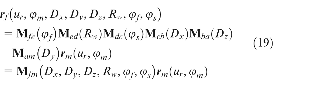
where
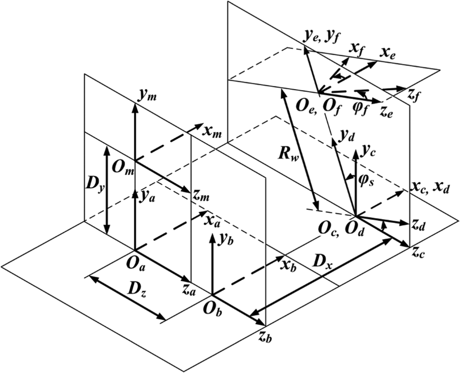
Coordinate systems for milling the spur face gear based on the five-axis milling machine.
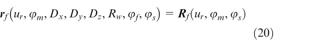
In equation (19), ϕf, Dy, and Dz are functions of ϕs (see equations (16)–(18)), Dx is a constant and is determined by the tooth width of the face gear, and Rw is also a constant and equals the distance from the workpiece swivel axis to the tooth root of the face gear. Thus, the tooth surface of the spur face gear is expressed as
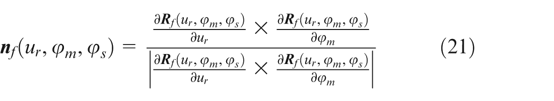
The unit normal vector of the spur face gear is expressed as
The tooth surface and normal vector of the spur face gear are determined from equations (16)–(21) combined with the equation of meshing as follows
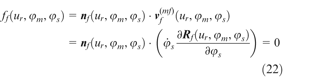
where
Calculation of the radial feed range ΔDx
During the face gear milling process, the milling cutter must implement radial feed motion to generate the entire tooth surface. Thus, the radial feed range ΔDx is larger than the tooth width. The radial feed range ΔDx is expressed as

where Ri and Ro are the inner and outer radii of the face gear, respectively, Δd is the increment and Δd = 2 mm.
Calculation of the swivel angle range Δϕs
During the milling process, the face gear must rotate around the workpiece swivel axis Ow (see Figure 9). The value of the rotation angle of the face gear equals the swivel angle of the milling cutter. In the milling process, the swivel angle range Δϕs should be selected reasonably. A small range can cause the tooth surface to be partially unprocessed, whereas a large range will hamper the production efficiency.
Figure 11 shows the limit positions of the milling cutter. The minimum value of ϕs occurs when the milling cutter is located at the initial position, as shown in Figure 11, and the minimum value of swivel angle ϕs(min) = 0. The maximum value of ϕs occurs when the milling cutter rotates around the centre of the imaginary shaper Os from the root to the tip of the spur face gear. The maximum value of the swivel angle ϕs(max) is expressed as
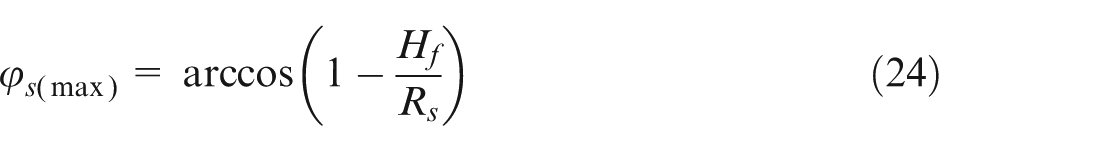
Limit positions of the swivel angle of the milling cutter.
where Hf is the tooth depth of the spur face gear.
Thus, the swivel angle range Δϕs is expressed as

where Δϕ is the angle increment and Δϕ = 2°.
Experiments
Spur face gear milling cutter
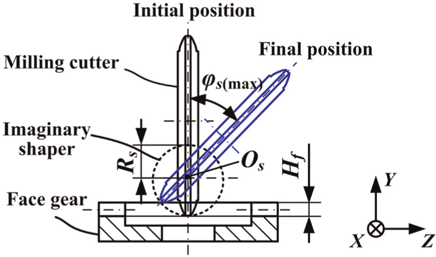
The milling cutter is designed and manufactured based on the design method presented in section ‘Design of the spur face gear milling cutter’. The design parameters of the milling cutter are listed in Table 1. The milling cutter is constructed from powder metallurgical high-speed steel (PMHSS) ASP 2030 and coated by physical vapour deposition (PVD) of AlCrN. The face gear milling cutter used in the experiments is shown in Figure 12.
Design parameters of the face gear milling cutter.
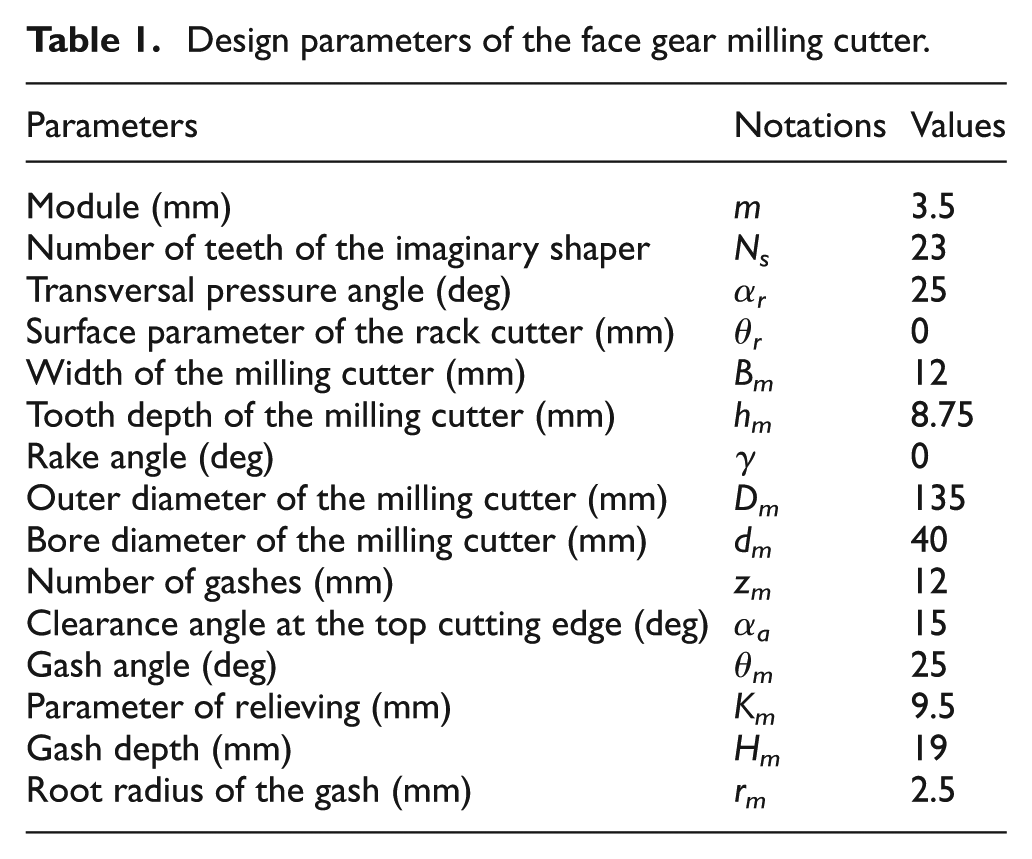
Face gear milling cutter used in the experiments.
Five-axis face gear milling machine
According to the milling principle of the spur face gear, a five-axis face gear milling machine is developed to achieve high-efficiency and high-precision CNC milling for the face gear. The machine has five numerically closed-loop controlled axes (X, Y, Z, A, B) and can implement the prescribed motions between the face gear and milling cutter. The rectilinear axis (X, Y, Z) strokes are 550, 500, and 650 mm, respectively. The A axis stroke is −105° to 15°. The power of spindle motor is 12 kW, and the maximum speed of spindle is 2400 r/min.
Spur face gear milling experiments
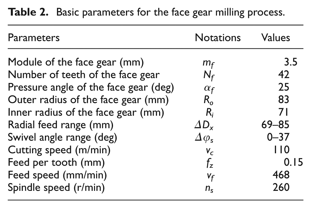
The spur face gear milling experiments were performed on the above-mentioned machine. The basic parameters for the face gear milling process are listed in Table 2. The numerical control codes were edited and transmitted to the face gear milling machine using the milling method presented in section ‘Milling method for the spur face gear based on the five-axis face gear milling machine’, and the basic parameters are listed in Table 2. Figure 13 shows the spur face gear milling process. The milling cutter rotates at a constant speed and translates along the negative Y axis. The face gear rotates around its own axis and workpiece swivel axis simultaneously, as well as translating along the positive Z axis. These translational and rotational motions are applied to generate the tooth surface. Figure 14 shows the machined spur face gear.
Basic parameters for the face gear milling process.
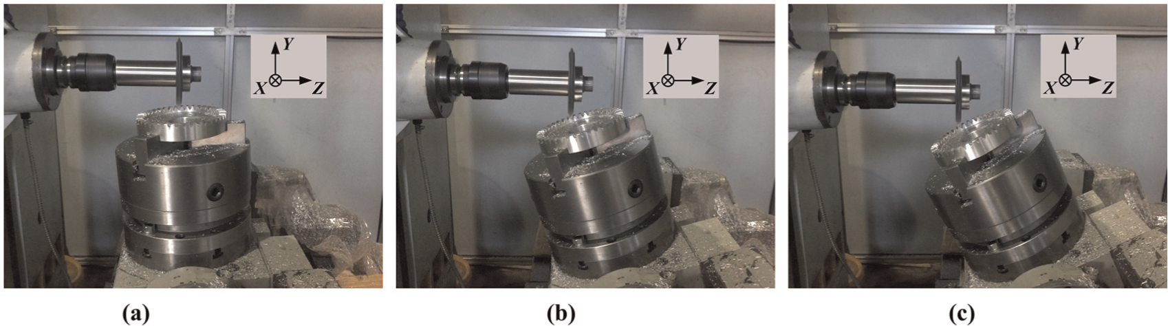
Spur face gear milling process: (a) beginning of milling, (b) middle of milling, and (c) end of milling.
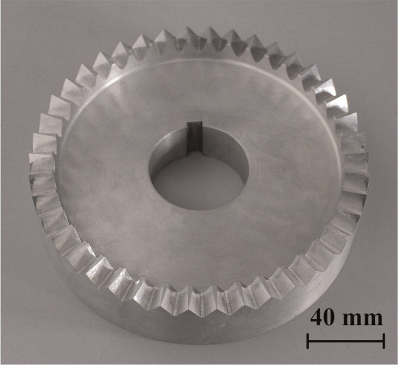
Machined spur face gear.
The tooth surface deviations were measured on a coordinate measuring machine (CMM) Leitz PMM-C 700. A rectangular grid of 45 data points on the tooth surface is predefined (5 and 9 data points along the tooth depth and tooth width, respectively) and used to determine the deviations. The theoretical space coordinates and normal vectors of the 45 data points are calculated by equations (16)–(22). The data points of the machined tooth surfaces were measured using the CMM. The deviations between the theoretical and measured tooth surfaces are shown in Figure 15. Figure 15 illustrates that the maximum deviation is 22.6 µm. Because there are no criteria for evaluating the face gear accuracy, the accuracy standard of the bevel gear was adopted to evaluate the face gear accuracy. According to the Chinese National Standard GB11365-89 Accuracy of bevel and hypoid gears, a tooth surface deviation of 22.6 µm satisfies accuracy grade 7, and this face gear accuracy can meet the requirements of roughing. Thus, the generating milling method for spur face gear proposed in this article is verified experimentally.
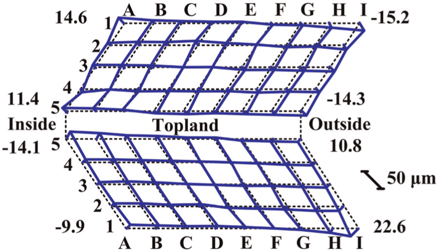
Measurement results of the tooth surface.
Conclusion
This article presents a generating milling method for the spur face gear to develop a face gear process with high accuracy and high efficiency. The main findings are as follows:
The milling principle of the spur face gear is studied. By simulating the shaper motion, the milling cutter can be applied to produce the spur face gear. Based on the generating milling method and theory of gearing, the tooth profile of spur face gear milling cutter is deduced. The structure and design parameters of the cutter are determined, and the milling cutter is manufactured to perform spur face gear milling experiments. The results of the experiment have shown that the milling cutter can be used to produce high-accuracy spur face gears.
A five-axis face gear milling machine is developed based on the requirements of machine motion during the face gear milling process. The mathematical model of the milled spur face gear is established based on the structure of the milling machine, and the milling method for the spur face gear is studied. The radial feed rang and swivel angle rang of the milling cutter are also calculated.
The spur face gear milling experiments were performed on a five-axis milling machine. The tooth surface deviations of the machined spur face gear were measured on a CMM Leitz PMM-C 700, and the maximum deviation is 22.6 µm. The experiment results have demonstrated that the generating milling method can be applied in precision milling of the spur face gear. The proposed method is confirmed to be an effective approach in improving the machining accuracy and production efficiency of the spur face gear compared to the plunge milling method.
Footnotes
Appendix 1
Declaration of Conflicting Interests
The author(s) declared no potential conflicts of interest with respect to the research, authorship, and/or publication of this article.
Funding
The author(s) disclosed receipt of the following financial support for the research, authorship, and/or publication of this article: This research is supported by the Key Project of Advanced Research Foundation of China (No. 9140A18020113HX) and Advanced Research Project of China (No. 5131802X, No. 5131812X).