
Abstract
Kinetostatics of a robot is an essential component of robotic analysis that includes actuation distribution and torque control. The extant methods mainly include the static transfer formulae and force Jacobian matrix algorithms based on the Denavit-Hartenberg (D-H) method. They can calculate the joint driving torque, but there are some limitations. This paper proposes a kinetostatics approach for analyzing the driving torque of serial manipulators. The instantaneous work done by the external load is expressed with reciprocal screw. It is the key idea of the approach to derive the kinetostatics equation in screw form and determine the required torque at each joint. This methodology is straightforward for programming. Through kinetostatic analysis of some typical serial manipulators, this paper shows the process of establishing the kinetostatics of every joint to calculate the torque in Plücker coordinates. The general spatial manipulator was analyzed and the solution demonstrates the universality of the method presented in this paper. In addition, the kinetostatic analysis method applies to all kinds of serial manipulators.
Introduction
Kinetostatic analysis of a robot is essential for actuation distribution, load balance, and precise control. It is the kinetostatics of mechanism to solve the wrench of joint space when the mechanism remains at rest or slow-motion state. When the serial robot interacts with the environment through the end effector, forces and moments will be generated at the contact position. For example, when extracting heavy objects, the end effector needs to balance the external load. When machining parts, the end effector needs to bear the force from the workpiece. In general, the joint force of the serial manipulator is generated by a separate actuation and transmitted to the end effector through the links to balance the external load. For a mechanism, the link and the joint are subjected to various forces. However, when the mechanism remains at rest or moves slowly, the influence of inertia force and other dynamic effects can be ignored, and only the static effect needs to be considered. In engineering, we hope to find out the feasible joint force and torque under the conditions of maintaining the static equilibrium of the system. Therefore, the relationship between static force and motion in joint space and end effector space plays a vital role in torque control of the robotic arm.
Therefore, the robot kinetostatics is an important research topic, and the existing methods can be found from some literatures.1,2 There are two main methods, one is based on the Static transfer formula, and the other is the Force Jacobian matrix algorithm based on the D-H method in one Cartesian coordinate system.
The serial robot is an open-chain mechanism composed of a series of links. Without considering the dynamic effect, the forces and moments in the joint space are caused by the forces and moments in the end effector space. From the perspective of Newton mechanics, the static transfer formula is derived from the end link to the primary link. 3 Similarly, Li et al. 4 investigated the statics of a 3-DOF robot for Milling based on this method. Juan and Mirats Tur 5 reviewed the basic problems of static analysis. Fischer 6 studied the statics of cylindrical joints by separating forces and moments. Lee et al. 7 calculated the parameter of linkage required to achieve static equilibrium within the static torque range In addition, some static balancing methods about spherical joint mechanisms, 8 planar linkage mechanisms,9,10 Tensegrity mechanisms, 11 and multi-link suspension 12 have also been developed. This method is widely used in different fields.13–16 The second method is the force Jacobian matrix approach based on the D-H convention. In a Cartesian coordinate system, work is the dot product of the force vector and displacement vector. From the perspective of work, the static equation of the serial robot in Cartesian coordinate system is derived. 2 It is worth noting that the core of this method is to solve the velocity Jacobian matrix based on the D-H method. On this basis, Han et al. 17 proposed a static model for serial articulated manipulators based on the analysis with standard D-H convention. Kim et al. 18 analyzed a planar double-wishbone suspension mechanism with the new Jacobian method. This method is also often adopted to analyze the kinematics and statics of the manipulator.19–21
In the aforementioned research, seldom were the kinetostatics discussed in screw coordinates in such a way. The main contributions of this paper are therefore as follows: (1) The proposed method is very concise in calculating the joint force of a serial robot based on the reciprocal screw. Statics calculation is simpler since it requires only the external load exerting on the end effector and the twist matrix of velocity for the manipulator, and does not need disassembling every joint to study the force for all joints. The calculation of the twist matrix is more convenient than that of the Jacobian matrix. (2) Different from the traditional statics method, the kinetostatics equation of a serial robot is derived in screw form. The instantaneous work done by the external load is expressed with reciprocal screw theory and the kinetostatics equation is derived under the condition of zero virtual power. (3) The real-time output of the manipulator is realized by a numerical algorithm, which is convenient for computer programming. In this study, computer programming that constructs equations of equilibrium for the studied mechanism is extended to analyze the kinetostatics of manipulators. (4) By describing the motion and force in terms of twist and wrench, a unified description method can be established in one coordinate frame, which makes the mechanism analysis more straightforward.
Screw kinetostatics
For the prescribed inputs of actuator velocity

where S is called the twist matrix. Twist matrix can be expressed as

in which

where p represents the pitch of a screw.
Note that a rotational screw, which is commonly used to represent rotational joints, can be obtained by setting the pitch

where vector
Equation (1) expresses the twist of the serial manipulator. The twist matrix is formed by the unit screws of the rigid body, and it can be programmed on a computer for general calculation.
Similar to kinematic analysis, the force of a rigid body can be expressed by a wrench. The driving forces/torques for the specified wrench on the end effector are expressed by
The reciprocal screw theory indicates that the constraints exerted to the point attached to the end effector are reciprocal to its twist. Two screws,
Furthermore, the twist and wrench are expressed by using Plücker coordinates 24


In this way, the reciprocal product of two screws can be expressed as

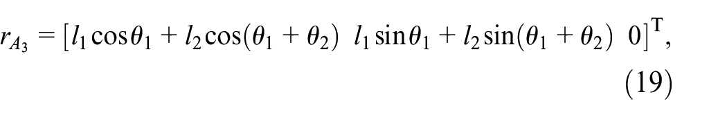
From the above discussion, we know that any generalized instant velocity of a rigid body can be described by a twist, and any set of generalized forces that act on a rigid body can be described as a wrench. A screw vector can be expressed by using the Plücker coordinates for a twist or wrench. 24 By describing the motion and force using the twist and wrench, a unified description method can be established in screw form, which makes the mechanism analysis more easy.22,23
Kinetostatics of the serial manipulator
Figure 1 shows the serial manipulator composed of multiple links connected by rotational pairs. The twist matrix is

A serial manipulator in space.
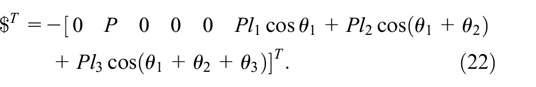
There is a torque input by the motor at each rotational joint in the kinematic chain. Assume that the instantaneous work done by the input torque is

According to the reciprocal screw theory, we gain that the instantaneous work done by the external load is

where
Because

Equation (9) can be expressed as follows:

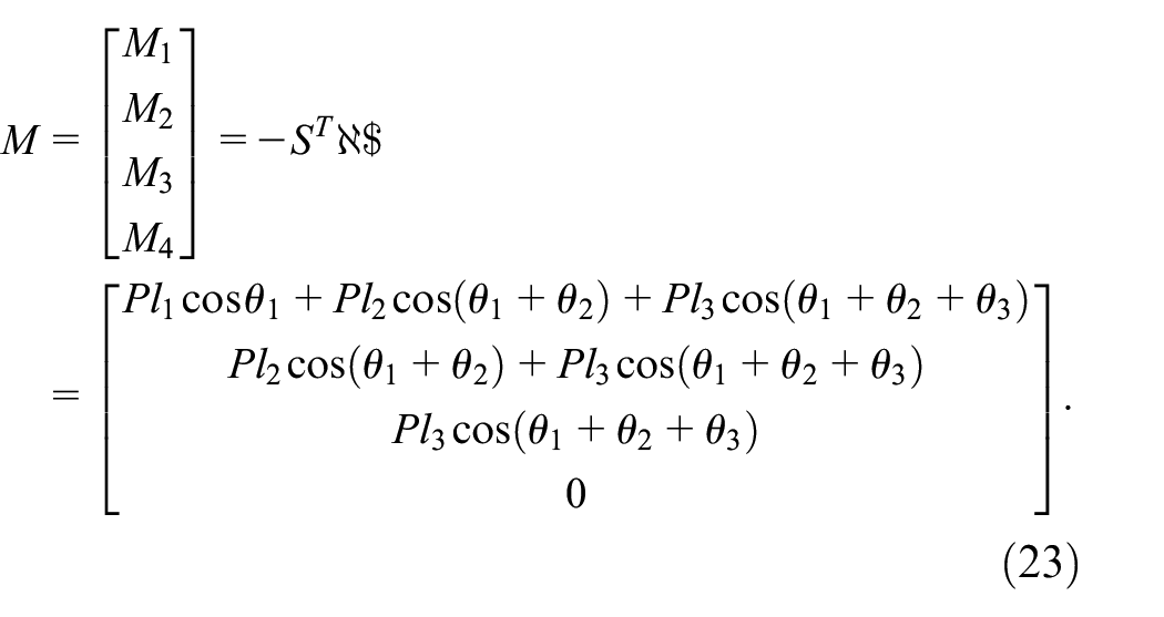
For a balanced kinematic system, equating the input and the output virtual powers, one obtains

Substituting equations (10) and (11) into equation (12) presents

Since

Therefore, torques for all joint motors are expressed in the vector form of

Through the above analysis, we easily analyze the kinetostatics of serial manipulators. By programming the algorithm, the torques required by the motors of a serial robot can be easily obtained. It should be pointed out that the relationship between the angular displacement, time, and angular velocity during the moving process should be satisfied as follows:

where
Determine the initial amount, including the length of each link
Calculate other angle variables at
All angular displacements at
Substituting $ and
To solve the input torques in a period, we should update the twist matrix
Substituting the twist matrix
In summary, the process of torque control and actuation distribution for the kinetostatics of a serial robot is shown in Figure 2. The process not only expresses the motion and operating force of the robotics system in a unified way but also realizes the real-time acquisition of joint torque and is convenient for control. Based on the kinetostatics strategy, the corrected joint torque for torque control and actuation distribution can be obtained.

The process of the kinetostatic analysis of a serial robot.
Analysis of typical serial manipulators
A planar redundantly actuated robotic arm
Figure 3 illustrates a planar 4-DOF redundant robotic arm. Establish a coordinate frame shown in Figure 3, where the coordinates of the end effector are

The redundant robotic arm.
The twist matrix of the end effector can be gained from equation (1). At this time,
In the absolute coordinate system, the coordinates of these joints are


Therefore, the screw matrix is

The wrench of the end effector is
Based on the proposed kinetostatics analysis method, we get that
The primary steps to get the input torque of each joint were given. The trajectory of the robot is also shown in Figure 4(a). The inverse kinematics can be referred to Zhao et al. 22 and Gan et al. 25 and joint angular velocity was calculated, as shown in Figure 4(b).

Motion parameters of a 4-DOF redundant robotic arm: (a) motion trajectory of the redundant robotic arm and (b) joint angular velocity of the redundant robotic arm.
Next, the kinostatics for redundantly robotic arm can be performed programmatically
Stipulate the length of each link and the angular displacement of each joint. Table 1 shows the initial parameters.
After all initial structure parameters at t = 0 are brought into equation (15), we get the initial torques at t = 0.
Through equation (16), the angular displacement will be replaced at the next moment. Finally, we obtain the motion performance of the robot under the input moment within a period.
Initial parameters of the redundant robotic arm.

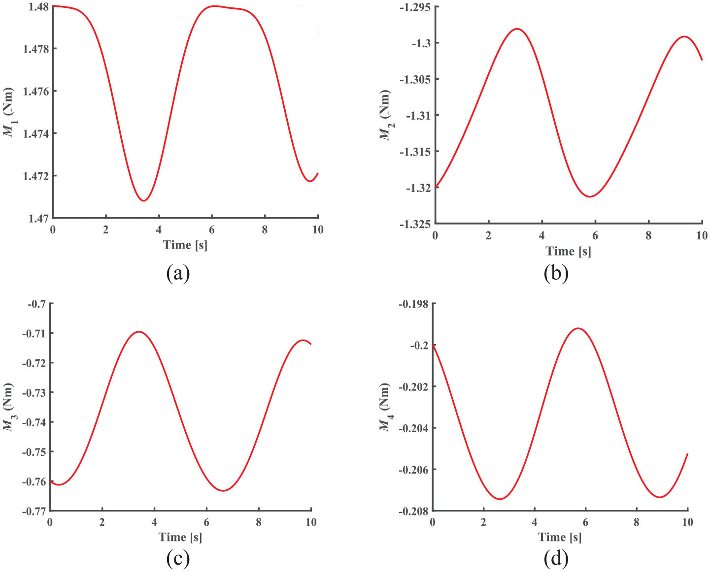
The proposed algorithm is programmed, and through numerical calculation, the torque curve of each joint is illustrated in Figure 5. It can be seen that this algorithm solves the joint torques very succinctly.

Torque of each joint for the 4-DOF redundant robotic arm: (a) torque of joint 1, (b) torque of joint 2, (c) torque of joint 3, and (d) torque of joint 4.
The torques of the motors at every joint of the serial robotic arm are changing cyclically as the robot starts to move from the initial parameters listed in Table 1.
4R spatial manipulator
Figure 6 shows a 4R spatial-type manipulator. The spatial type involves four twist screws, namely

A spatial-type 4R manipulator.
The position vector of all joints was calculated geometrically from Figure 6:


where
These unit axial vectors for rotational joint are expressed as follows:


These unit screws of pure rotation are expressed as follows:

As shown previously, the twist matrix of this spatial manipulator is

Furthermore, the end effector is utilized to realize the grasping operation of the object, and the external load is

Suppose
Structure parameters and initial values of the 4R spatial type manipulator.


Motion parameters of the 4R spatial manipulator: (a) motion trajectory of the 4R manipulator and (b) joint angular velocity of the 4R manipulator.
Therefore, by substituting equations (34) and (35) into equation (15), the actuation of the 4R manipulator was obtained. The driving torque of the 4R manipulator can be calculated in a period (see Figure 8).
The simulation results of the joint torque for the 4R spatial manipulator: (a) the torque of joint 1, (b) the torque of joint 2, (c) the torque of joint 3, and (d) the torque of joint 4.
This example shows that the kinetostatics algorithm proposed in this paper not only fits in with the planar serial mechanism but also suits the spatial mechanism of multiple degrees of freedom.
Six-axis spatial robot
There are 6-axis vectors of pure rotation in the 6-axis spatial robot shown in Figure 9. Each axis vector is attached to a joint. The 6-axis manipulator consists of two parts, namely, a primary joint and a minor joint. The six joints of the 6-axis robot are all rotary ones. There are six columns in the twist matrix that is expressed as follows:


The general case of a 6-axis robot.
The link coordinate system of the 6-axis robot is shown in Figure 10. An absolute coordinate system is established on the base, and an end coordinate system is attached to the end effector.

Schematic diagram of a 6-axis robot.
The position vector of the point
In this simulation, the angular velocity of the robot joint and the trajectory of the robot end effector are shown in Figure 11. The initial structural parameters are shown in Table 3.

Motion parameters of the 6-axis robot: (a) motion trajectory of the 6-axis robot and (b) joint angular velocity of the 6-axis robot.
Geometric parameters and initial values of a 6-axis robot.

In this case, the joint driving torques of the manipulator are used as the input. Based on the geometric parameters and initial values, the torques
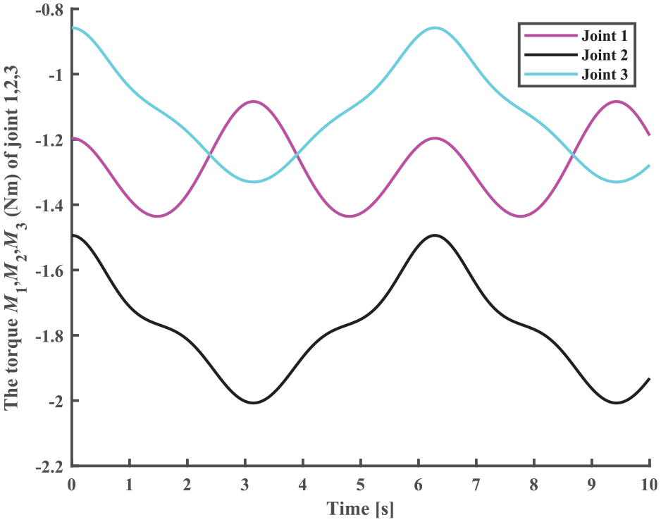
The torque of joint 1, 2, 3 for the 6-axis robot.
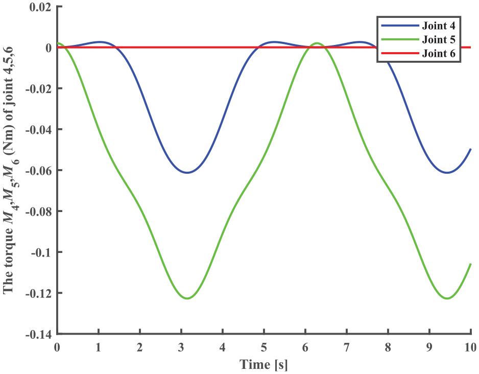
The torque of joints 4, 5, and 6 for the 6-axis robot.
From Figures 12 and 13, we find that the motors at joints 1, 2, 3, 4, and 5 are changing cyclically. The torque of joint 6 is constantly zero. This is true from Figure 13 since all the external forces pass through the center of joint 6. Moreover, the maximum torque value of joint 5 is greater than that of joint 4. This is because
Based on the analysis of joint torque with a 6-axis robot, the numerical algorithms are efficient and comprehensible in calculating the torques of all joints. Furthermore, the joint torque of a spatial serial multi-chain robot can be dynamically controlled on time by applying this kinetostatics algorithm.
Discussion
The essence of kinetostatic analysis is to analyze the equivalent transformation of forces between different coordinate systems. The principle of equivalence is to make two force systems equivalent. The equivalence principle includes the static equilibrium principle and the virtual work principle. Next, we discuss the differences between the two classical methods and our methods.
Static transfer formula
According to Craig 1 , it can be known that the static transfer formula between two neighbor links is

where

Static equilibrium of neighbor links.
The joint torque to keep the system in static equilibrium is the dot product of the joint axis vector and the torque vector applied on the link

To solve the joint torque using this method, it is necessary to disassemble each joint and recurse the force transmission between two links one by one. Take the robot arm with
Force Jacobin matrix based on D-H convention
From the perspective of work, the force Jacobian matrix method presents the joint torques

where
The joint torque is the vector product of

For rotational joints,

where
Using this method, it is necessary to write the transformation matrix of each joint coordinate system relative to the 0-coordinate system, which is a process of concatenation. When there are
Screw kinetostatics
The joint torque is the reciprocal product of the twist matrix and end effector force screw, as shown in equation (15).
The main advantage of the screw method is that the twist matrix is generated into the unit screw through each joint. Unlike the construction of the Jacobian matrix based on D-H convention, the screw kinetostatics can solve the twist matrix more easily because there are only two coordinate systems. On the one hand, if the two coordinate systems are established according to D-H convention, the unit screw only needs the third and fourth columns of the transformation matrix. On the other hand, the unit screw can be obtained more easily through the Rodrigues transformation. On the contrary, the D-H method usually involves complex calculations, and some scholars have compared them 26 in the differential kinematics of robot manipulators.
Based on the discussions above, it can be concluded that our method is simpler than the statics transfer method in calculation steps and the force Jacobian method in calculation cost. In addition, our method has realized computer programming, and three cases verify the universality of the method.
Conclusions
A new approach is proposed for kinetostatics of serial manipulators. The method considers that the instantaneous work done by the external load is expressed with reciprocal screw. It makes good use of the fact that the screw of a rigid body is composed of force and moment of a marking point on the body that coincides with the origin to express the external loads of a linkage. The kinetostatic equation in screw form is very concise and can solve the torques of joint space. Compared with the static transfer formula, the method proposed in this paper can directly solve the joint torque of the robot without disassembling the joint. Compared with the force Jacobian matrix method, our method reduces the calculation in solving the twist matrix.
Representative redundant robotic arms and spatial manipulators were selected for case studies. The proposed method was used to analyze the manipulators, and the calculation results were validated through simulations. Through the kinetostatic analysis of typical serial mechanisms, this paper shows the process of establishing the torque model in Plücker coordinates. The results indicate that the proposed method is extremely straightforward and provides a very convenient way for programming at a computer. Hence, the method can be utilized in control and motion planning of a robot.
Footnotes
Appendix

| Notation | Meanings of the notation |
|---|---|
| the velocity vector of the actuated joint | |
| the twist (velocity screw) of the end effector | |
| the twist matrix | |
| dual vector of the actuated joint | |
| unit axial vector for a rotational joint | |
| p | the pitch of a screw |
| the position vector of a point on the axis of the screw | |
| $ | the wrench (force screw) of the external load |
| the position vector of the action point | |
| the instantaneous work done by the input torque | |
| the instantaneous work done by the external load | |
| the column vector of torques for all joint motors | |
| reciprocal product of two screws | |
| the joint angular displacements at | |
| the joint angular displacements at | |
| interpolation cycle time | |
| the homogeneous transformation matrix |
Handling Editor: Chenhui Liang
Declaration of conflicting interests
The author(s) declared no potential conflicts of interest with respect to the research, authorship, and/or publication of this article.
Funding
The author(s) disclosed receipt of the following financial support for the research, authorship, and/or publication of this article: This work was supported in part by the Basic Research Project Group of China under Grant 514010305-301-3, in part by the National Natural Science Foundation of China under Grant 51575291, in part by the National Major Science and Technology Project of China under Grant 2015ZX04002101, in part by the State Key Laboratory of Tribology, Tsinghua University, and in part by the 221 Program of Tsinghua University.