
Abstract
To suppress chatter is very important for ensuring processing quality and efficiency in ultrasonic-assisted grinding of thin-walled workpiece of SiCp/Al composites. Based on the chatter mechanism analysis, a stability analysis model is built and the analytical method is proposed. The cutting parameters can be selected reasonably based on the lobe diagram of stability, and the experiments were conducted using the parameters of selected points on lobe diagram. The experimental results show that the cutting force and surface roughness of unstable points are much larger than that of stable points, the vibration marks appear on the workpiece surface with unstable machining, and the surface quality is better in stable machining, which indicate that the chatter could be suppressed by this method to guarantee machining quality and efficiency.
Introduction
Thin-walled part has been widely used in aerospace owing to high load ability and low weight. SiCp/Al composites have outstanding properties such as high bearing ability, high specific strength, high temperature resistance, light weight, etc.1–3 This material has been used to manufacture thin-walled workpiece, however, it is difficult to machine due to the reinforced particles involved in aluminium matrix and the processing difficulty increases with increasing particle volume fraction.4,5 There have been a lot of studies about machining SiCp/Al composites with some conventional and non-conventional processing methods in published literatures, but these methods could not fully satisfy the requirements for high accuracy and high efficiency in machining of SiCp/Al composites parts with complicated shapes.6,7 Ultrasonic-Assisted Grinding (UAG), also known as rotary ultrasonic machining, has many excellent processing characteristics. It is appropriate for machining many difficult-to-cut materials and fit for SiCp/Al composites processing as well.8–10
SiCp/Al thin-walled workpiece manufactures need to meet strict quality requirements and it has many features, such as big cutting allowance, poor manufacturability, high requirements for shape coordination, low relative stiffness, high accuracy, etc., which is easy to generate deformation, instability and chatter due to cutting force variation during processing. Existing research shows thin-walled part stiffness decreases as wall thickness minishes, which will lead to reduction of natural frequency. When exciting force frequency multiplication of machining system is close to natural frequency, chatter will occur easily. To avoid chatter happen, ancillary shoring will be added on the key position of thin-walled part generally to improve stiffness, however, this method is little effect for precious part machining. If cutting parameters drastically reduce, cutting chatter will avoid to some extent, but it will seriously affect the processing efficiency and do not conform to economy requirement. 11
In 2010, Adetoro et al. 12 considering nonlinearity of cutting force coefficient, axial entrance angle and axial cutting depth, presented an improved prediction method of stability lobes using nonlinear dynamics to adapt various changes on account of different tools in thin-walled part machining. Kolluru and Axinte 13 investigated coupling effect of dynamic responses of milling cutter and workpiece, and on this basis dynamic modelling is conducted, then optimised stability lobe is got. In 2014, Arnab carried out stability analysis for thin-walled cylinder turning and developed a processing model, using finite element analysis, semidiscretisation and nonlinear cutting force method. The result indicated that workpiece thickness and tool position have an important influence on processing stability. 14 Li et al., 15 proposed a nonlinear dynamic model to restrain chatter in milling of thin-walled part made of titanium alloy, and cut-in angle of clearing chatter was obtained according to this model. Jia et al. 16 designed a pneumatic fixture to control support force on the thin-walled workpiece, and the three dimension stability lobe diagrams were obtained to predict the chatter stability. Zheng et al. 17 obtained the relationship between material removal and vibration response and indicated the vibration amplitude of processing system increases as the workpiece thickness lessens. Sun et al. 18 proposed a novel stability analysis method for rotary ultrasonic milling thin-walled workpiece through defining an ultrasonic function angle, and the stability lobe diagrams were achieved according to the semi-discrete method. The current literatures indicate that most of thin-walled parts are made of aluminium alloy or titanium alloy and plentiful studies have been conducted for chatter suppression, but these research methods could be as important references for chatter analysis in UAG of thin-walled workpiece of SiCp/Al composites.
This article is oriented to develop a simple and effective method to restrain chatter during processing. Based on the characteristics of UAG, material behaviour of SiCp/Al composites, chatter mechanism analysis and dynamic characteristics of machining system, a mathematical model of stability analysis and stability judgement criterion are established, where the key parameters in the model are determined through modal and cutting experiments. Then the stability lobe can be obtained using MATLAB, enabling optimisation selection for spindle speed and axial cutting width. The SiCp/Al composites reinforced with 45% volume SiC particles of average size 3 μm were used to machine a thin-walled plate on the basis of optimised parameters. The experimental results indicate that chatter is avoided and processing quality is enhanced through this method in UAG of SiCp/Al thin-walled workpiece.
Model building and analysis
In machining process, cutting vibration will bring about many negative effects, such as fatigue failure of machine tool workpieces, reduction of machining precision and surface quality, tool wear or breakage, etc. The cutting vibration can be divided into the following categories: free vibration, forced vibration, self-excited vibration and mixed vibration, where the self-excited vibration has the greatest effects on machining system. Kumabe Junichiro, a Japanese scholar, presented the insensitivity vibration principle, which explained the relation between workpiece natural frequency fn and tool vibration frequency f during cutting process. When f ≈ fn, the machining dynamic change is similar to ordinary cutting chatter appeared during the cutting process; when f/fn > 3, the machining dynamic change will be stable, this characteristic is equivalent to improve the rigidity of machining system, and it has the same effect as improvement of clamping force, usage of support frame and improvement of spindle rigidity. 19 In this article, the ultrasonic frequency is greater than 20 kHz that is much higher than the workpiece natural frequency, which satisfies the insensitivity vibration principle and the ultrasonic vibration will not cause chatter in UAG of SiCp/Al composites workpiece. Chatter in general machining is mainly caused by the interaction of tool regeneration effect and workpiece regeneration effect, and the ratio of two effects varies in different processes. In the process of SiCp/Al composites machining by UAG, due to the effect of ultrasonic vibration, the tool wear is very low, and the tool damage almost does not appear, so the tool regeneration effect has a low impact on chatter. Due to existing of reinforced particles, there will be various defects in the machining process, such as particle breakage, particle packing, particle shedding, etc., which will lead to fluctuations of cutting force and remove thickness, and the chatter will occur in severe case. Therefore, the regeneration effect of workpiece is the main reason result in chatter when SiCp/Al composites processed by UAG.
The chatter in UAG machining process is similar to that in ordinary grinding. The machining system is simplified, including discretisation of continuous system, linearisation of nonlinear system and neglecting of the change of workpiece modal characteristics caused by material removal. On the basis of the above analysis, the machining process model is established, as shown in Figure 1.

Model of UAG process.
Suppose that at any time t during UAG processing, the following equation is satisfied

Where U0(t) is the total feed of grinding wheel (mm), Xm(t) is the structural deformation of machine tool (mm), Xc(t) is the contact deformation between tool and workpiece (mm), Wg(t) is the total tool wear (mm) and Ww(t) is the total removal of workpiece (mm). In equation (1), the expressions of each item is


Where Gm(s) is the transfer function of machine tool structure, Fn(t) is the radial cutting force (N), kc is the contact stiffness between tool and workpiece (N/mm), Tg is the tool regeneration effect period (s), Tw is the workpiece regeneration effect period (s), ΔWg(t) is the instantaneous tool wear (mm) and ΔWw(t) is the workpiece instantaneous removal (mm). ΔWg(t) and ΔWw(t) can be represented as


Where kg is the tool wear coefficient (N/mm), kw is the workpiece cutting force coefficient (N/mm) and b is the axial cutting width (mm).
The machine tool structure is simplified as a single degree of freedom system, and the transfer function is

where km is the structural stiffness of system (N/mm), ωn is the natural frequency of system (Hz) and ξ is the damping ratio of system. Taking the Laplace transform of equations (1) to (7) and combining the equation (8), the block diagram of the system of UAG machining process can be obtained, as shown in Figure 2.

System block diagram of UAG process.
Based on Figure 2, the transfer function of UAG process is
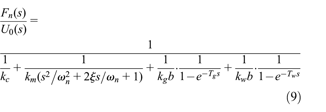
The UAG is more stable than milling, so the length-diameter ratios of tool have relatively little effect on chatter during machining, and this problem is not considered in this article. The tool wear is very small because of diamond grinding wheel and ultrasonic vibration used in UAG machining process. Therefore, the regeneration effect of tool surface on the chatter of machining system is extremely weak and can be ignored. The contact deformation between tool and workpiece includes tool contact deformation and workpiece contact deformation. In the UAG process of SiCp/Al composite thin-walled workpiece, the size of the tool is small, the size of the workpiece relative to the tool is large, and the stiffness of the thin-walled workpiece is much smaller than that of the tool. In addition, due to the existence of SiC reinforced particles, abrasive particles and SiC constantly collide during the machining process, the particle breakage, rotation and pull out will appear, which is more likely to lead to the regeneration effect of workpiece surface. Therefore, the chatter in machining process is mainly the regeneration effect of workpiece surface, and the total contact deformation between tool and workpiece can be replaced by the contact deformation of workpiece. Hence, equation (9) can be simplified as
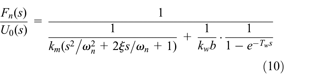
The system characteristic equation can be derived from equation (10), as shown below.

According to the above analysis, the structural characteristics of SiCp/Al composite thin-walled workpiece and the processing characteristics of UAG determine the main factors affecting the processing stability of the model, and also reflect the correlation between them. After acquiring the modal parameters and other main parameters of the thin-walled workpiece, the model can be used to analyze the machining stability of processing.
The system characteristic equation describes the inherent properties of the machining system, which are not affected by the input and output parameters of the system. The distribution of characteristic roots reflects the state of the system, and the general form of characteristic roots is s = σ + jω. The relationships between the real part of the characteristic root and the stability of the system are as follows: when σ = 0, the system is in a critical stable state; when σ > 0, the system is in an unstable state; when σ < 0, the system is in a stable state.
When σ = 0, s = jω is substituted into equation (11), the axial cutting width is the critical stable axial cutting width blim and λ = ω/ωn, then the following equation can be obtained.

according to Euler’s formula,

On the basis of equations (12) and (13), the following equations can be got.
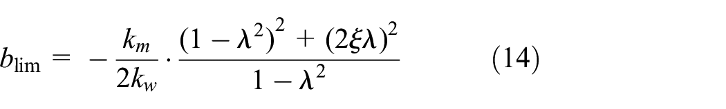

The equation (16) can be obtained based on (15), as shown below.

where
The relationship between the regeneration effect period of the workpiece and the spindle speed is S = 60/Tw, which is substituted into equation (16), and the following expression can be obtained.

Where k = 0, 1, 2, 3, …n.
Based on equations (14) and (17), The stability Lobe diagram of the machining system can be drawn by MATLAB.
Experimental procedures and analysis
The purpose of UAG processing stability analysis of SiCp/Al thin-walled workpiece is to reduce cutting chatter and maximise production efficiency under the premise of meeting requirements of machining quality. According to the machining stability model and analysis method, the machining stability Lobe diagram of thin-walled workpiece can be obtained with the machining system modal parameters and cutting force coefficients determined by modal and cutting force experiments. Based on the stability Lobe diagram, the UAG processing parameters of SiCp/Al thin-walled parts can be optimised to achieve the effective combination of processing efficiency and processing quality.
In this paper, an LMS modal test system (LMS-SCADAS-III) was used to determine the modal parameters of the tool system and SiCp/Al thin-walled workpiece in UAG processing centre (DMG Ultrasonic70-5). The tool type was MT-ER20-i//Do.Φ12.0-2-6-40-D91H-MES3-Kz.N, which outside and inside diameters were 12 and 10 mm, and the mean grain size was 91 μm. The ultrasonic vibration frequency and amplitude used in experiment were 38,500 Hz and 10 μm respectively. The main experimental equipment includes LMS data acquisition system, force hammer and acceleration sensor. In the experiment, the method of multi-point excitation and fixed-point measurement response were used to test. The area on the test tool and the workpiece were divided equally to determine the measuring points. The percussion method was used to excite each measuring point with striking five times, and the average value was acquired. Finally, the measured data were analysed by LMS analysis system to determine the modal parameters values. Figure 3 shows the distribution of measurement points on the thin-walled plate and the ultrasonic tool. The dimensions of thin-walled plate are 100 mm × 64 mm × 4 mm, and there are 45 and 10 measuring points on the plate and tool respectively.

Measuring points distribution on thin-walled plate and tool.
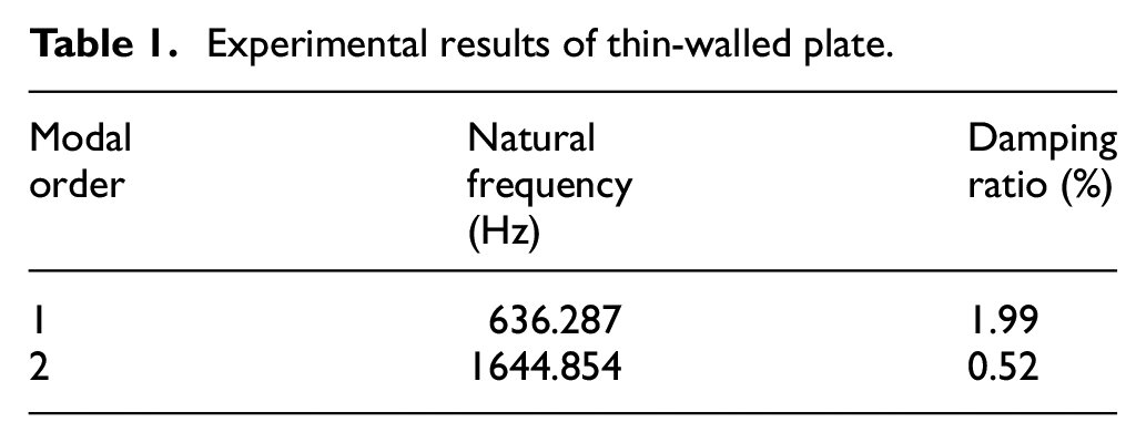
The experimental results are shown in Tables 1 and 2.
Experimental results of thin-walled plate.
Experimental results of ultrasonic tool.

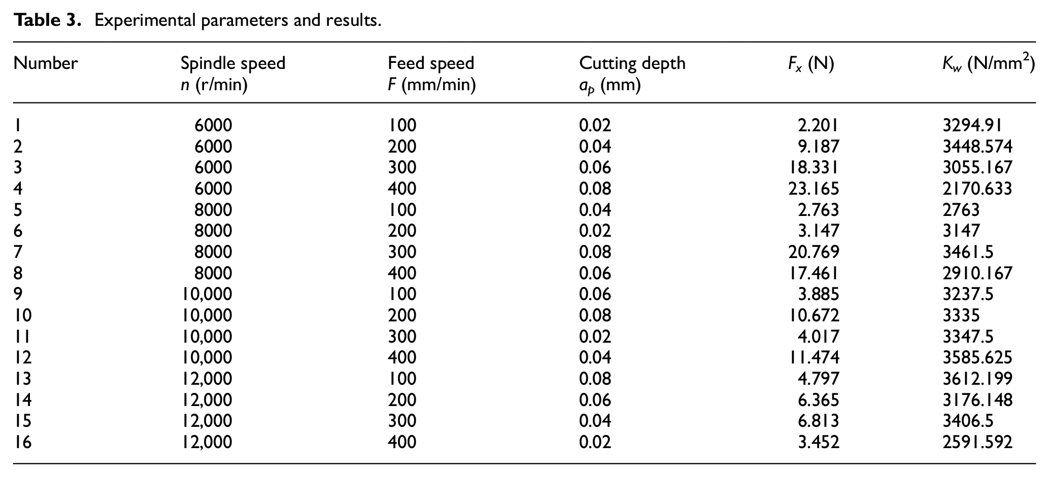
The determination of cutting force coefficient mainly aims at the normal force (radial force) which causes machining chatter, and it is determined according to the rapid calibration method of the cutting force coefficient proposed by Budak and Altintas. 20 The normal force can be expressed as

where fr is the feed speed (mm/r), ap is the cutting depth (mm) and kw is the cutting force coefficient (N/mm2).
In the light of equation (18), the cutting force coefficient can be acquired by the cutting force experiment. The orthogonal experiment with three factors and four levels was carried out and the cutting forces were measured using dynamometer (KISTLER9257B), as shown in Table 3. Based on the cutting experiments, the average value of cutting force coefficient can be calculated as 3158.938 N/mm2.
Experimental parameters and results.
The first mode of the machining system has the greatest effect on the machining chatter, so only the first mode parameters are used in stability analysis. The chatter generally occurs in the part with weak rigidity, that is, the natural frequency is low. In the machining process, the first natural frequency of the thin-walled plate is much lower than that of the ultrasonic tool, so the first mode parameters of the thin-walled plate are used in analysing, and the parameters are shown in Table 4.
Parameters of stability analysis.

The stability Lobe diagram can be obtained based on the above parameters. The stability lobe diagram is divided into three areas: area I is the unconditionally stable processing region, area II is the conditionally stable processing region, and area III is the unstable processing region. The nine points are selected in lobe diagram, where a1, a2, b1, b2, c1, c2 are stable processing points and a3, b3, c3 are unstable points, as shown in Figure 4. The processing quality is different with the parameters of various corresponding points in Lobe diagram, and the chatter will occur using the parameters of unstable processing region to machine workpiece. The experimental setup is shown in Figure 5, and the cutting parameters and experimental results of the nine points are shown in Table 5.

Selecting points on Lobe diagram of thin-walled plate.

Setup of thin-walled plate machining.
Parameters and results of processing points.

Figure 6 shows the workpiece surface after machining. The a1, a2, b1, b2, c1, c2 are located in the stable machining area, no vibration marks appear on the surface and the surface roughness values have little change. The a3, b3 and c3 are located in the unstable machining area, and slight vibration marks appear on the surface of b3 and c3, while no vibration marks appear on the surface of a3 due to some random factors. Although vibration marks perhaps not appear during unstable machining, it can be seen from Table 5 that the surface roughness and radial cutting force values of unstable machining points increase substantially. The SEM images of machined surface of stable point b1 and unstable point b3 are shown in Figure 7, and there are obviously more scratches and pits on the surface of b3 than that of b1. Because the stability analysis method neglects some secondary factors in the machining system, there are some errors between the analysis results and the actual machining situation. Based on the experiment results of thin-walled plate machining, the stability analysis method is effective in suppressing machining chatter and can determine the reasonable range of machining parameters. In the actual processing, various influencing factors should be fully considered, and the best values could be obtained within the reasonable range of machining parameters.

Machined surfaces of thin-walled plate.

The SEM images of machined surface: (a) stable point b1 and (b) unstable point b3.
Conclusions
In this work, the chatter mechanism of thin-walled workpiece of SiCp/Al composites in UAG machining is analysed. The chatter that may occur in the machining process is mainly regeneration chatter, and the regeneration effect of workpiece is the primary cause which affects the chatter. The machining process conforms to the theory of insensitive vibration cutting, so the ultrasonic vibration has no effect on the chatter. Based on the general grinding process model, a mathematical model for UAG machining stability analysis of SiCp/Al composites thin-walled workpiece is established considering the machining characteristics of UAG and the material characteristics.
According to the stability analysis model, the method of UAG processing stability analysis is determined, and the key parameters in the model can be obtained through cutting experiments. Using MATLAB, the Lobe diagram of machining stability can be acquired, and the cutting parameters can be reasonably selected based on the Lobe diagram, which can achieve the purpose of improving machining efficiency, suppressing cutting chatter and ensuring machining quality.
The processing experiments were carried out based on the selected points. The experimental results show that when the parameters of unstable points are selected for machining, the cutting force and surface roughness are relatively large, and the vibration marks may appear on the workpiece surface; when the parameters of stable points are selected, the cutting force and surface roughness are smaller, and the surface quality is better. Therefore, through this method, the machining parameters can be reasonably selected to ensure the machining stability of thin-walled workpiece, avoid the occurrence of chatter and meet the requirements of machining quality and efficiency.
Footnotes
Handling Editor: Chenhui Liang
Declaration of conflicting interests
The author(s) declared no potential conflicts of interest with respect to the research, authorship, and/or publication of this article.
Funding
The author(s) disclosed receipt of the following financial support for the research, authorship, and/or publication of this article: This work is partly supported by Special Funding for Postdoctoral of Heilongjiang Province (Grant No. LBH-Z20203), Introducing Talent Scientific Research Start-up Project of Heilongjiang Bayi Agricultural University (Grant No. XDB2017-04), Introducing Talent Scientific Research Start-up Project of Heilongjiang Bayi Agricultural University (Grant No. XDB202002), School Cultivate Project Funding Scheme of Heilongjiang Bayi Agricultural University (Grant No. ZRCPY202104), Key Project for 3 Longitudinal Research Support Plan of Heilongjiang Bayi Agricultural University (Grant No. ZDZX202102). The authors would like to thank their generous support.