
Abstract
Regenerative chatter can easily occur in the milling process of thin-walled workpiece due to the inherently low stiffness. This article aims to predict the stability of thin-walled workpiece in the milling process with a complete dynamic model. First, multiple structural modes of thin-walled workpiece are taken into consideration, and a complete dynamic model of thin-walled workpiece milling system is developed. Then, a numerical integration method is used to achieve the stability lobe diagrams of the milling system and identify the chatter frequency. Besides, the major structural mode, which is responsible for the occurrence of thin-walled workpiece chatter in the milling process, is predicted. A series of milling tests concerning a general cantilever plate are conducted, and the test results agree well with the predicted results, which shows the effectiveness of the proposed method. Finally, the effects of milling tool and structural modes on milling stability are discussed separately, which could provide theoretical basis for the dynamic modeling of thin-walled workpiece in milling process.
Introduction
Thin-walled workpieces are extensively used in aeronautic industry. Unfortunately, chatter occurs easily in the milling process of thin-walled workpiece due to its inherently low stiffness, which is the major limitation to product quality and productivity. Besides, milling chatter could cause some other negative effects, such as excessive noise, disproportionate tool wear and so on. Therefore, the chatter problem in the milling process of thin-walled workpiece is a topic of enormous interest in manufacturing.
Traditionally, milling tool is regarded as flexible with respect to the workpiece. 1 Most researchers try to construct the stability lobe diagram (SLD) and then select optional machining parameters to ensure chatter-free operations. The regeneration phenomenon, which is the major cause of the milling chatter, is modeled mathematically by delay differential equation (DDE) with infinite dimensional state space, but its stability condition cannot be given analytically. Hence, several methods have been proposed to solve the problem. Smith and Tlusty 2 used the peak-to-peak (PTP) force diagrams in time domain to predict the milling stability limit. Altintas and Budak 3 developed a zeroth order approximation (ZOA) method for chatter prediction in frequency domain. Since the time varying dynamic cutting force coefficient matrix can be approximated by its Fourier series component, the ZOA method allows a rapid calculation of SLD compared with time domain method. This method has been extended to variable-pitch cutters, 4 honed tools 5 and so on.
Other research scholars tried to predict the stability of the milling process in state space. For example, Insperger and Stepan6,7 and Ding et al. 8 proposed the semi-discretization method (SDM) and the full-discretization method (FMD) to conduct stability analysis of the linear time-delay system, respectively. Zhang et al. 9 proposed the numerical integration method to obtain the SLD regarding the governing equations of the milling dynamic process as initial value problem for differential equation. To improve the convergence rate and computational accuracy, Niu et al. 10 presented a generalized form of the Runge–Kutta method (GRKM) based on a Volterra integral equation of the second kind. Li et al. 11 built an extended dynamic milling model including mode coupling and process damping, and proposed a second-order SDM to simultaneously predict the stability lobes diagram and surface location error by solving this extended dynamic model. Yue et al. 12 used FMD to predict the stability of the milling process by taking the characteristics of the contact between the tool and the workpiece into consideration. Qin et al. 25 developed a Chebyshev-wavelet-based method for accurate and fast milling stability prediction.
In the milling process of thin-walled workpiece, the stiffness of thin-walled workpiece is much lower than the milling tool, which means that the milling tool–workpiece system changes from the traditional flexible–rigid system to the rigid–flexible system. Hence, the variations of thin-walled workpiece dynamic characteristics, mainly caused by the tool position, as well as multiple modes of the structure should be taken into consideration to achieve the SLD. Bravo et al. 13 presented a method to obtain the three-dimensional SLD when both milling tool and workpiece have similar dynamic behaviors, where the third dimension is the tool position along the workpiece. Seguy et al. 14 analyzed the relationship between chatter instability and surface roughness in the milling operations of thin walls. Mane et al. 15 analyzed the dynamic interaction of milling tool and thin-walled workpiece by a finite element approach. Wu et al. 16 investigated the stiffness-strengthening effect of longitudinal torsional ultrasonic milling of thin-plate structures by analyzing the forced vibrations of the thin-plate structure under conventional milling and ultrasonic milling loading. Sun and Jiang 17 established a novel dynamic model for thin-wall milling systems by considering force-induced deformation effect.
Most studies in the field have focused on milling chatter prediction, but only a few research efforts have tried to investigate the dynamic behavior of thin-walled workpiece, such as chatter frequency prediction, influence of the structural mode interaction on milling chatter and identification of the responsible structural mode for the occurrence of milling chatter. In this article, a clear picture about the chatter frequency arising in the milling process of thin-walled workpiece will be given by establishing a complete dynamic model of thin-walled workpiece. Besides, the effect of the structural mode interaction on the milling chatter will be studied to identify the responsible structural mode for the occurrence of milling chatter, which could provide a theoretical basis for the active control of thin-walled workpiece milling chatter.
The structure of this article is organized as follows. In section “Dynamic milling model,” a general cantilever plate model is employed, and the dynamic model of the milling process of thin-walled workpiece is developed. A method for the prediction of the SLD and the identification of the chatter frequency is presented in section “Stability analysis and chatter frequency.” In section “Experimental validation and results,” the experimental procedures are presented and the dynamic behavior of thin-walled workpiece is analyzed. The effects of milling tool and structural modes on milling stability are discussed separately in section “Discussions.” The conclusions of the article are drawn in the last section.
Dynamic milling model
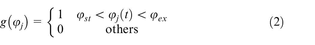
In this section, a general cantilever plate model is used to investigate the dynamic behavior of thin-walled workpiece, as shown in Figure 1. Traditionally, the end mill can be considered as a stack of differential disk elements. The linear milling force model is employed, and the milling force acting on the jth tooth corresponding to a differential element can be expressed as 18
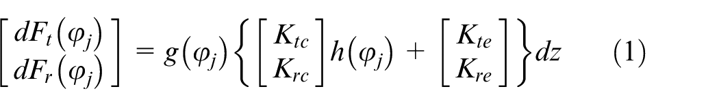
where
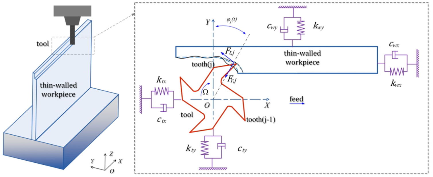
Dynamic milling model for thin-walled workpiece.
The angular position of the jth tooth
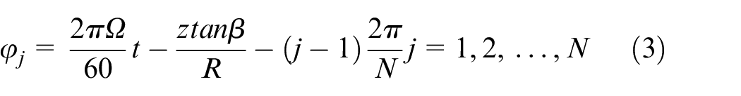
where
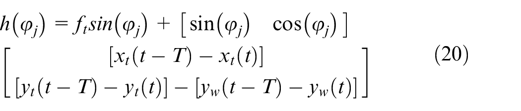
Therefore, the regenerative effect is considered and the instantaneous uncut chip thickness
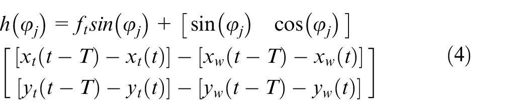
where
According to Figure 1, the total milling force acting on the milling tool can be given as 19
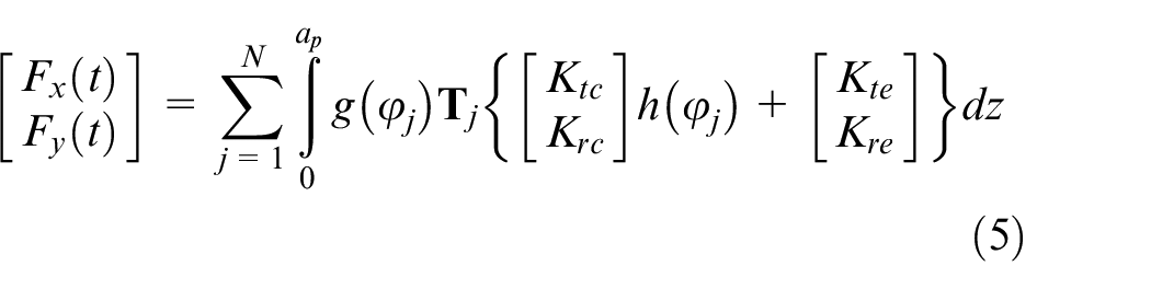
where
In this article, the first
The modal shape of the milling tool is normalized at the tip of the milling tool, and the dynamic response of the milling tool can be determined by
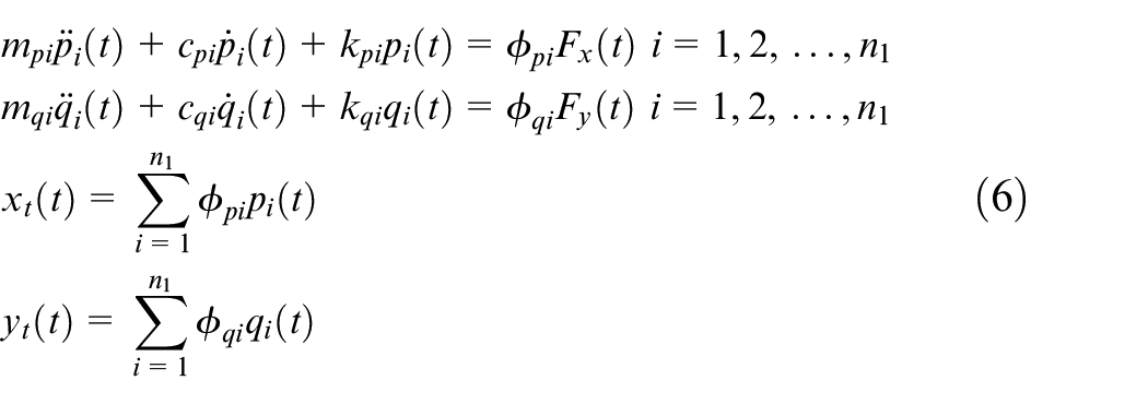
where
In terms of the milling tool, with the excitation of the milling force at
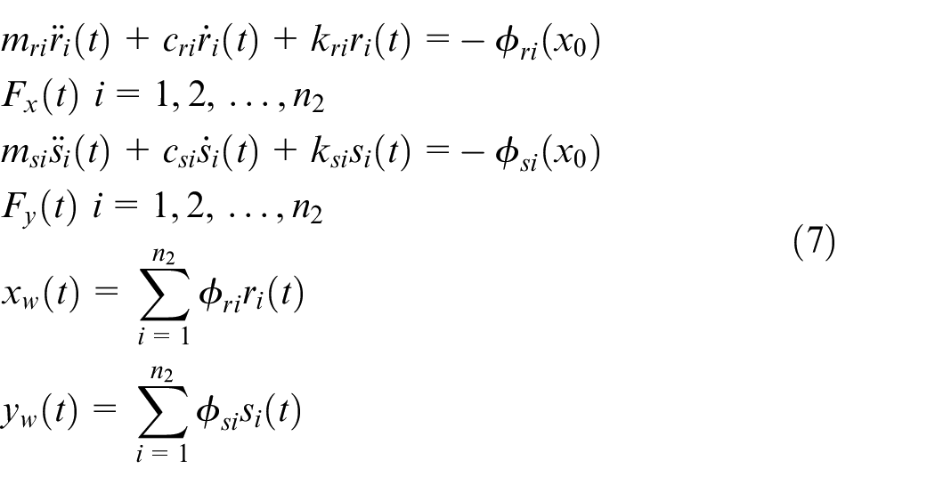
where
The dynamic parameters of the milling tool and the thin-walled workpiece mentioned above can be determined by the modal test, as shown in section “Frequency response function acquisition.”
By substituting Equations (4) and (5) into Equations (6) and (7), the dynamic control equation of the milling system can be expressed as follows
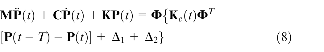
where
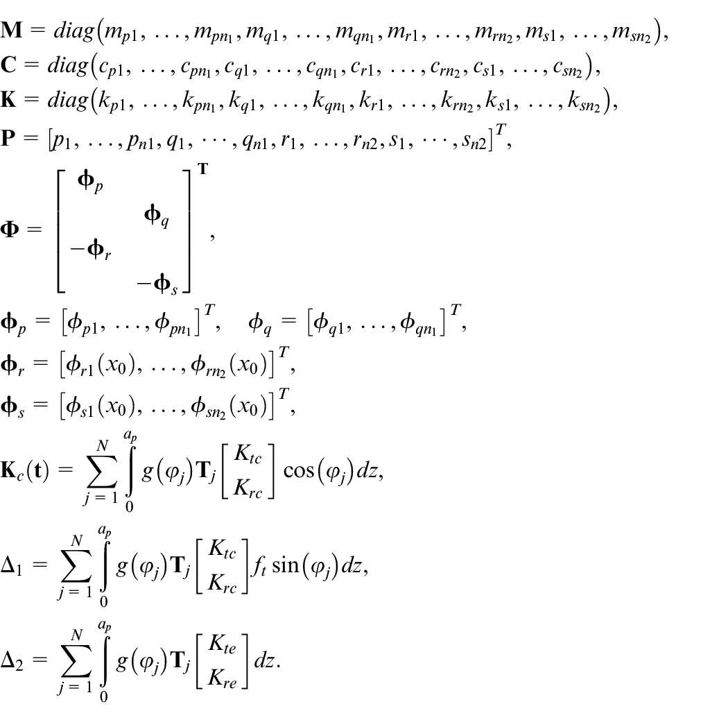
Since
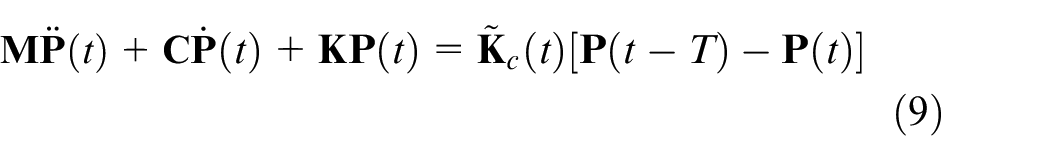
where
Considering that the stiffness of the thin-walled workpiece in the feed direction is high enough, the vibration of the workpiece in the feed direction can be neglected. Besides, it is generally considered that the bending stiffness of the thin-walled workpiece is much smaller than that of the milling tool. In other words, the milling tool can be regarded as rigid, and the vibration of the milling tool can be neglected (the effect of the milling tool on the milling stability will be discussed in section “Discussions”). Hence, the instantaneous uncut chip thickness

The dynamic control Equation (9) can be simplified as
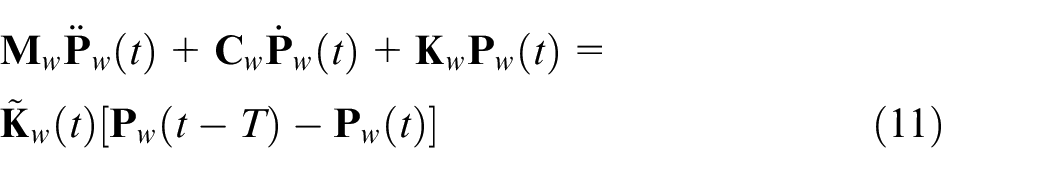
where
Stability analysis and chatter frequency
In this section, the numerical integration method 9 will be extended to the milling process of thin-walled workpiece by taking multiple structural modes into consideration.
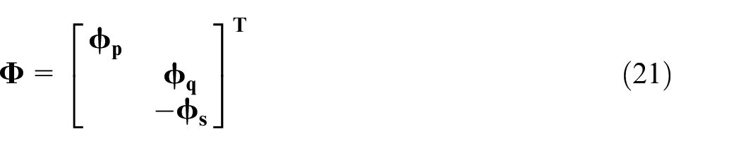
With the transformation

where
The time delay parameter T is equally divided into m small intervals, and the corresponding discretized time points are

where
The solution of Equation (12) over each time interval
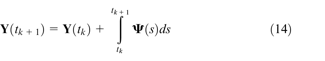
where
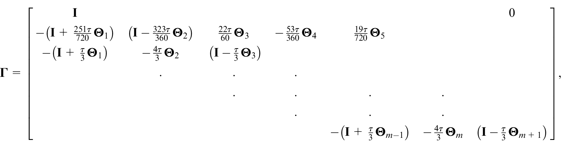
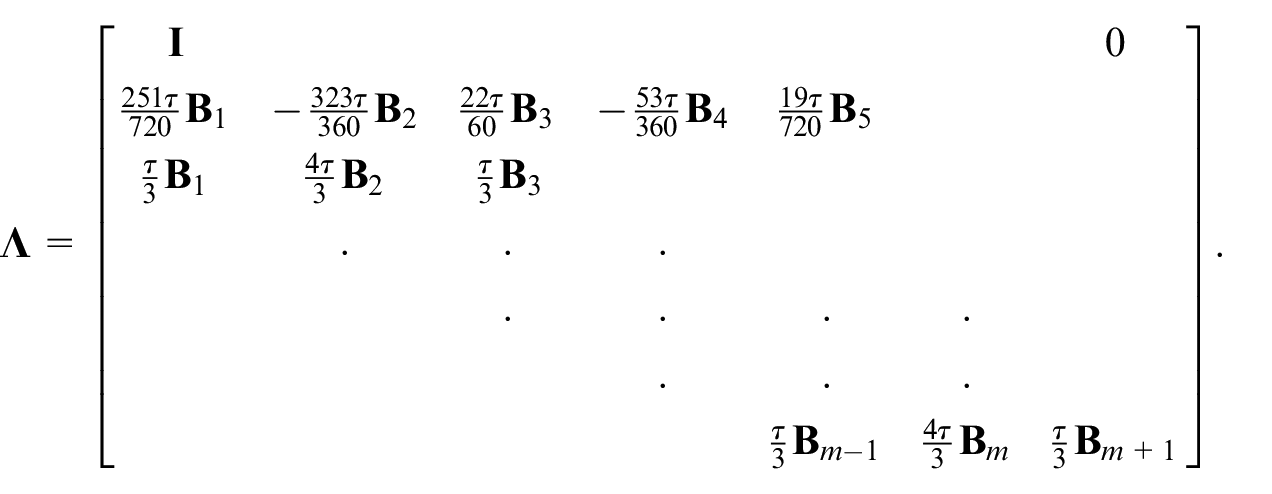
At time point
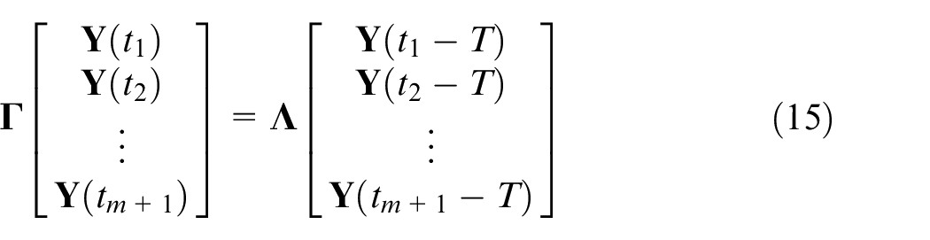
where
The transition matrix over one tooth passing period can be expressed as

Finally, the stability of the milling system can be determined based on the Floquet theory. The relevant characteristic multiplier
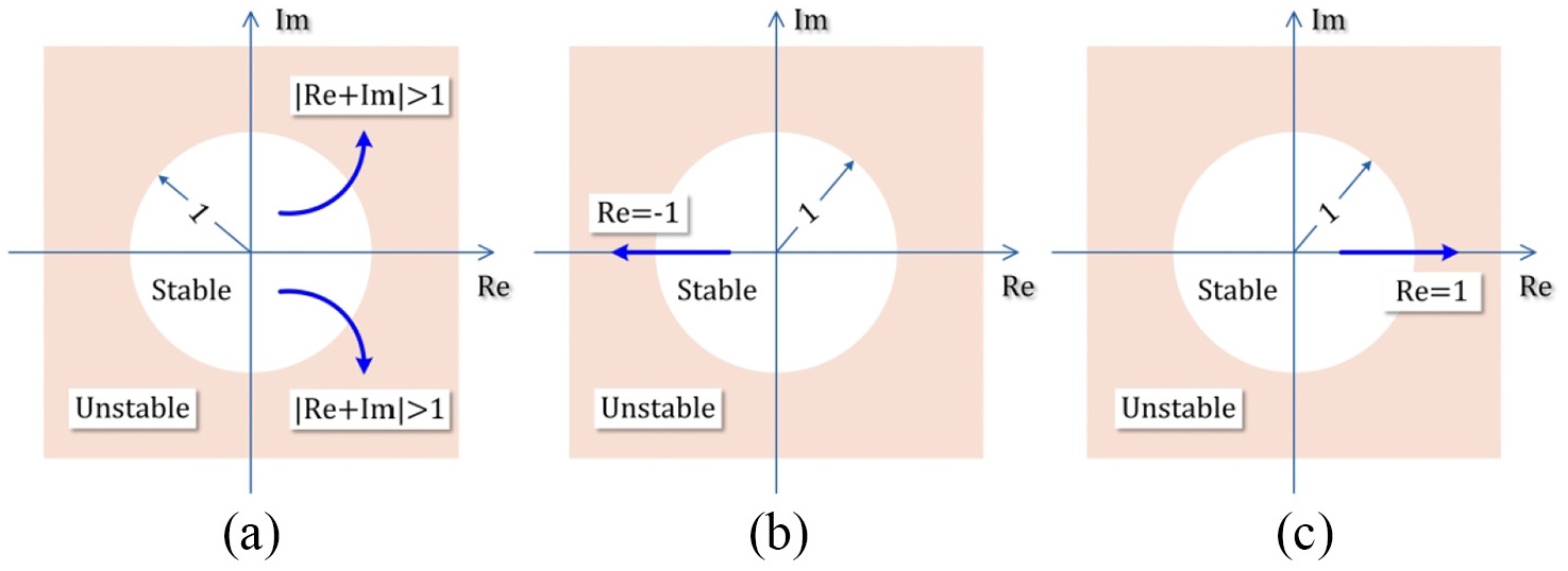
Unstable behavior in complex plane: (a) Hopf bifurcation, (b) period-doubling bifurcation and (c) period one bifurcation.
The arising chatter frequency for an unstable milling process can be determined for the case
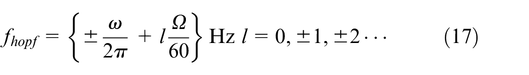
where
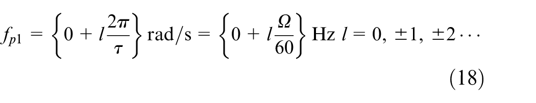
If the relevant characteristic multiplier is
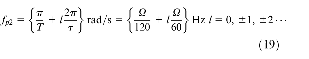
If the relevant characteristic multiplier is
Experimental validation and results
In this section, a cantilever plate is employed and the impact test is conducted to determine its modal parameters. Then the SLD of the thin-walled workpiece and the chatter frequency are predicted based on the method introduced in section “Stability analysis and chatter frequency.” Finally, a series of milling tests are carried out to verify the predicted results.
A cantilever plate, which is made of 7050 Aluminum, is used in this article, and the dimension of the plate is
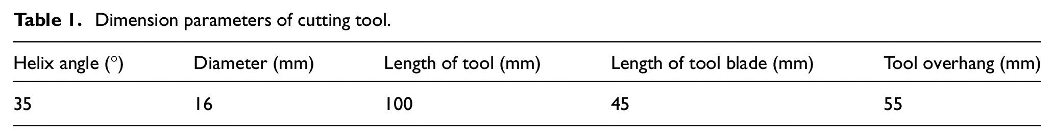
Dimension parameters of cutting tool.
Milling force coefficients acquisition
To predict the milling SLD and the chatter frequency, milling force coefficients should be calibrated in advance.
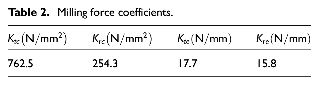
During the milling test of calibrating the milling force coefficients, milling parameters are selected to achieve stable milling process. The instantaneous milling forces are measured by the dynamometer Kistler 9255C and recorded by the software HRsoft. Based on the method proposed by Budak et al., 22 the milling force coefficients are calibrated through the test results, as listed in Table 2.
Milling force coefficients.
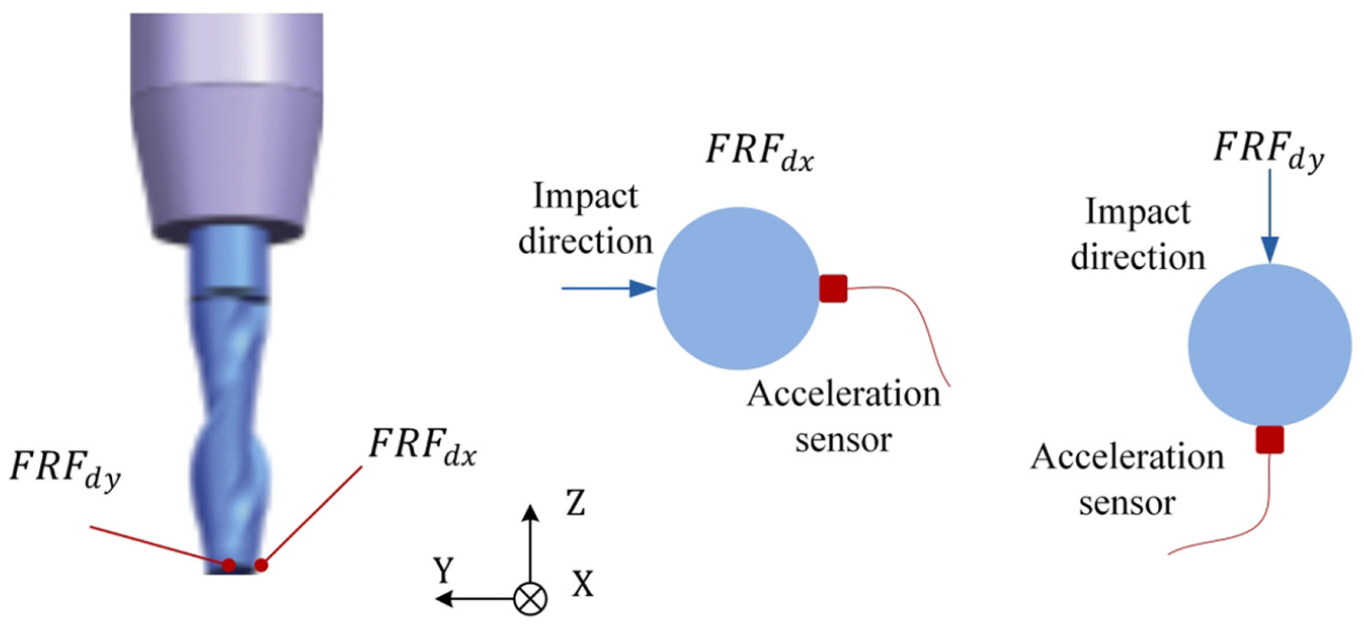
Frequency response function acquisition
As mentioned before, the diameter of the tool is
The variations of the thin-walled workpiece dynamic characteristics caused by the tool position are taken into consideration. Since the thin-walled workpiece is an axisymmetric structure, five measurement points (P1–P5) on the first half of the thin-walled workpiece in feed direction are selected, as shown in Figure 3(a). The direct FRFs of the measurement points are obtained by the impact tests.
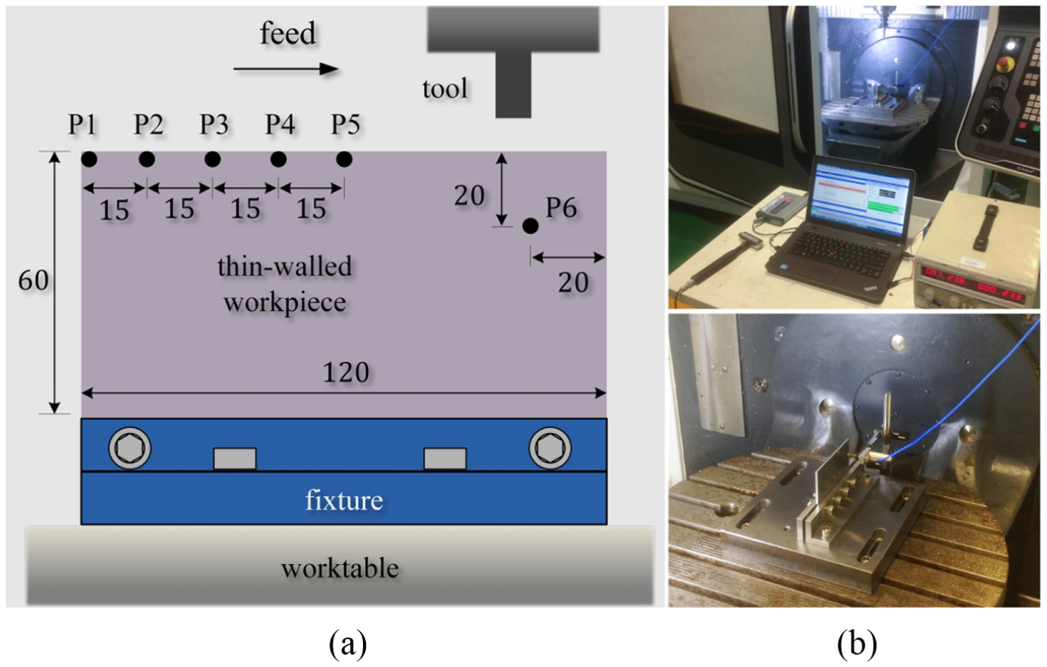
(a) Measurement points on the workpiece and (b) experimental setup for impact test.
During the impact tests, the impulse hammer Kistler 9724A2000 is used as the excitation source, and the response of the plate is acquired by the eddy current sensor. The response signals are measured and processed by the LMS SCADAS XS data acquisition system and the software LMS Test. Lab 14A, as shown in Figure 3(b). The impact test of each measurement point is conducted 10 times to eliminate the disturbance of noise. The sampling bandwidth, namely the cutoff frequency, is set as
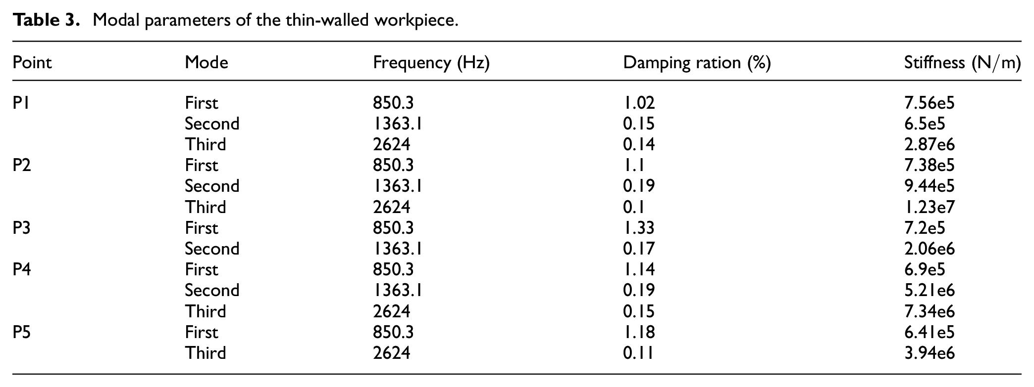
The impact test results are illustrated in Figure 4. It is noted that point P5 is situated on the node of the second modal shape of the cantilever plate. Hence, the second-order mode cannot be seen in the FRF of point P5. Similarly, point P3 is located at the node of the third modal shape of the cantilever plate. Hence, the third-order mode cannot be detected in the FRF of point P3. The modal parameters are identified by normalizing the mode shape of the driving point based on the peak-picking method,22–24 and the results are listed in Table 3.
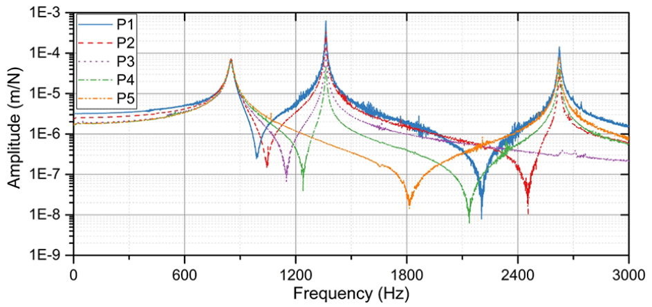
Measured FRFs of the thin-walled workpiece.
Modal parameters of the thin-walled workpiece.
Milling stability identification and chatter frequency prediction
After obtaining the milling force coefficients and the dynamic characteristics of the thin-walled workpiece, the numerical integration method, which has been introduced in section “Stability analysis and chatter frequency,” is employed to calculate the SLD and the chatter frequency of each measurement point.
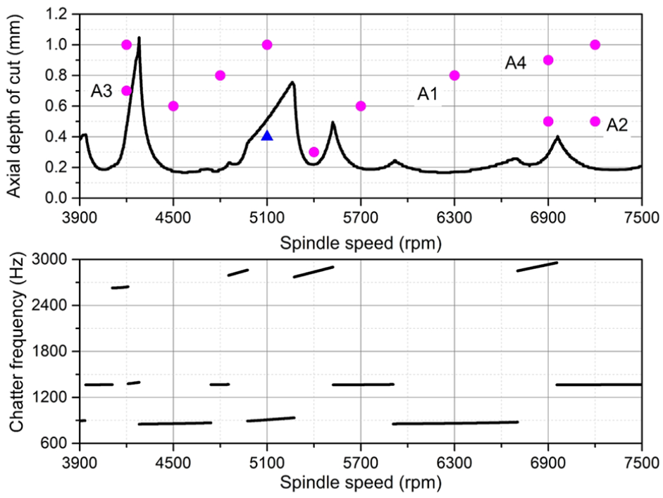
The stability charts are determined over a 240×200 sized grid of the spindle speed and depth of cut. The discretized number is set as 40, and the radial depth of cut is 1 mm, down milling. The calculated results are shown in Figures 5–9. ▲ means the milling process is stable when the tool passes the point, while • means chatter occurs.
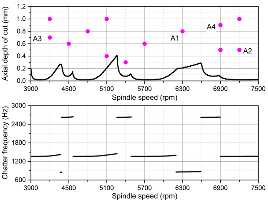
SLD and chatter frequency of point P1.
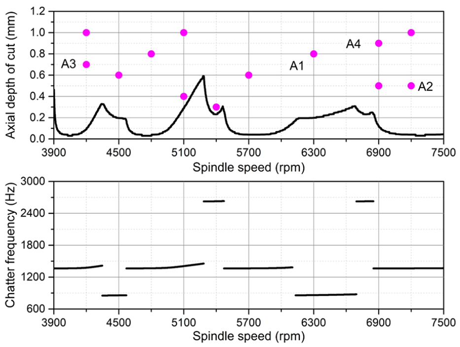
SLD and chatter frequency of point P2.
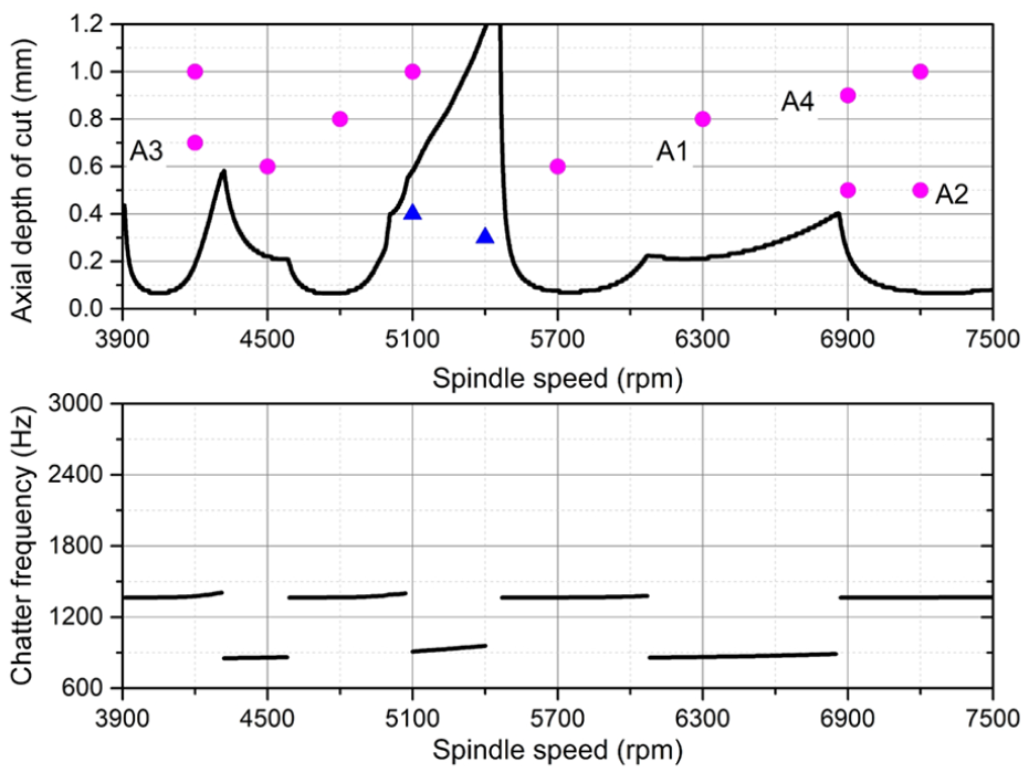
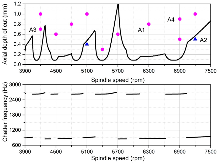
SLD and chatter frequency of point P3.
SLD and chatter frequency of point P4.
SLD and chatter frequency of point P5.
Clearly, there exist remarkable variations among the SLD of the five measurement points. With the increase of the structural stiffness from point P1 to point P5, the critical depth of cut is also enlarging. Besides, there does not exist any flip bifurcation.
Experimental verification
To verify the predicted SLD and the chatter frequency, a series of milling tests are conducted. Four typical parameter points (point A1, point A2, point A3 and point A4) on the predicted SLD are chosen, and the test results are discussed as below. In addition, the structural mode, which is responsible for the occurrence of the milling chatter, is also analyzed. During the milling tests, the vibration displacement signal of point P6 in Figure 3 is used to analyze the dynamic behavior of thin-walled workpiece.
The measured vibration displacement signal with the milling parameters of point A1
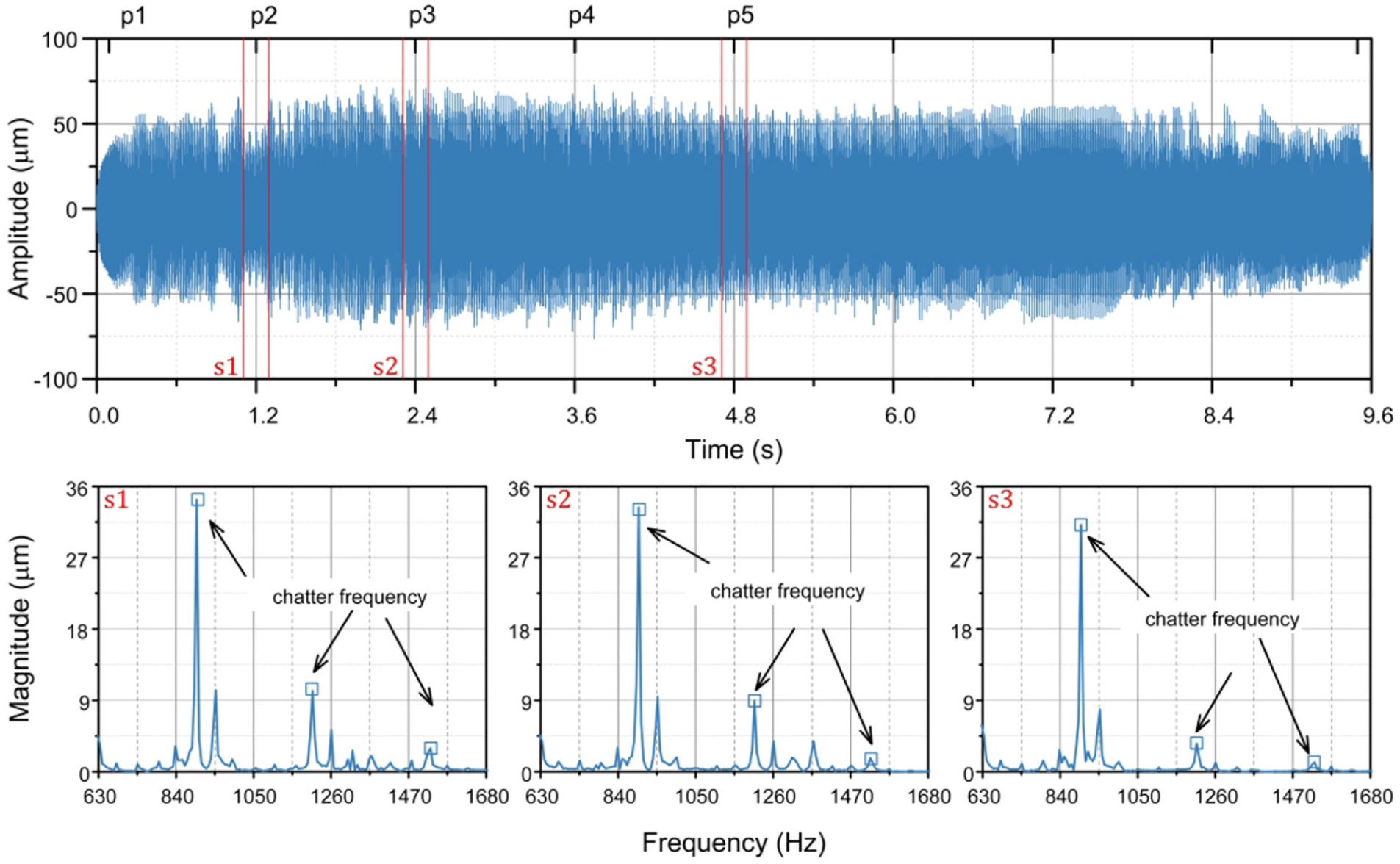
Test results with the milling parameters of point A1.
It is obvious that the whole milling process is unstable, which coincides with the predicted result. Three sub-signals
The quality of the machined surface is shown in Figure 11. Evidently the surface finish is poor, and chatter marks are clearly visible.

Surface finish of the workpiece with the milling parameters of point A1.
In terms of the milling process with the parameters of point A2
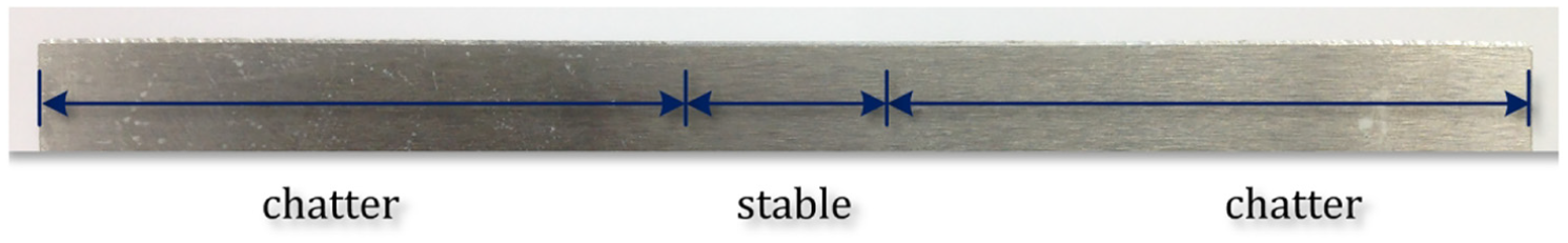
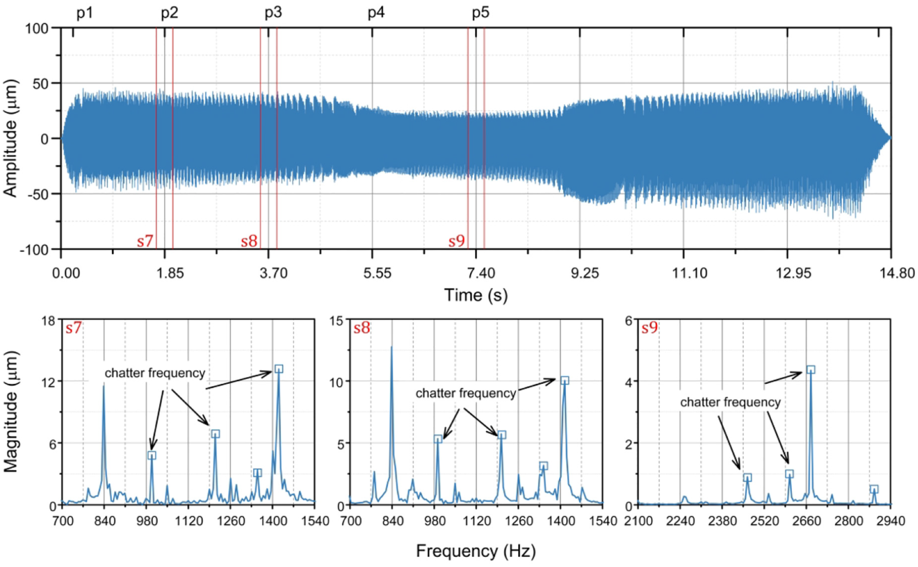
The test result, as shown in Figure 12, confirms that the milling process is unstable from P1 to P4, and then gradually turns to stable from P4 to P5 as the tool advances along the tool path. But, milling chatter appears again at about
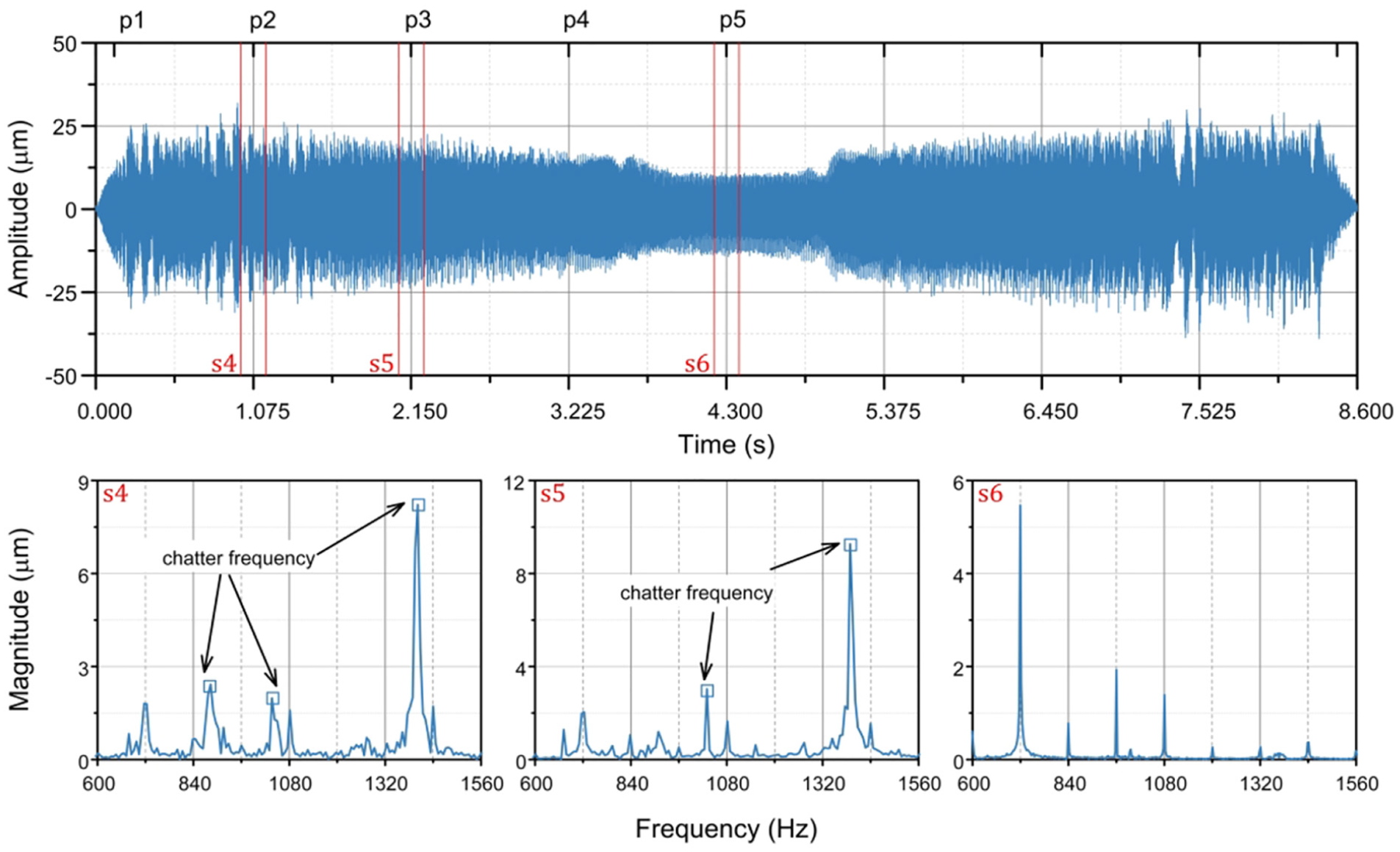
Test results with the milling parameters of point A2.
This result can be also seen from the machined surface in Figure 13. Clear chatter marks can be observed around the two ends of the thin-walled workpiece, whereas the middle section of the workpiece shows a smooth surface.
Surface finish of the workpiece with the milling parameters of point A2.
As for the point A3
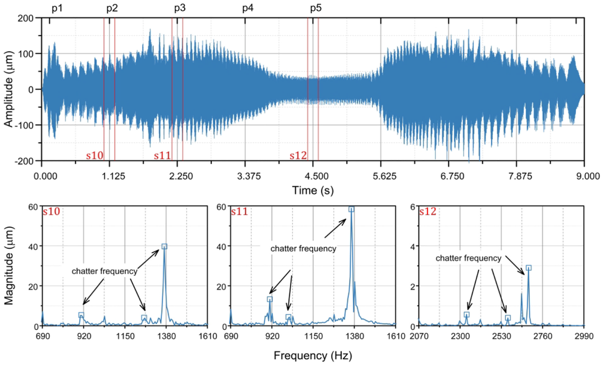
The test result can be found in Figure 14, which shows that the whole milling process is unstable. In simple terms, the milling process can be divided into three stages. Specifically speaking, at the beginning of the milling process, the main chatter frequency is
Test results with the milling parameters of point A3.
Then the chatter frequencies excited by the second-order structural mode fade away after the tool passes by point P3, and the chatter frequency (2675 Hz) excited by the third-order structural mode appears and dominates the milling process. In addition, the amplitude of the displacement signal decreases due to the reason that the stiffness of the workpiece in the middle section is much higher than those of the two ends. Obviously, the test result is basically identical to the predicted result. The surface finish is shown in Figure 15, and strong vibration marks can be observed, especially around the two ends.
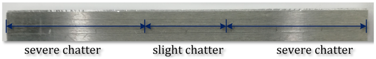
Surface finish of the workpiece with the milling parameters of point A3.
In terms of point A4
Test results with the milling parameters of point A4.

Surface finish of the workpiece with the milling parameters of point A4.
Discussions
Effect of milling tool on milling stability
To simplify the milling process, the milling tool is regarded as rigid and its vibration is neglected in section “Dynamic milling model.” In this section, the assumption will be evaluated to provide theoretical basis for simplifying the milling process.
When the milling tool is considered in the modeling process, the instantaneous uncut chip thickness
The transfer matrix
As mentioned in section “Milling force coefficients acquisition,” the diameter of the milling tool used in this article is
Modal test of milling tool.
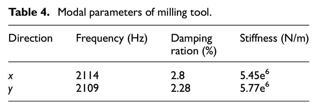
The impact test results are illustrated in Figure 19, and then the modal parameters of the milling tool are calibrated, as shown in Table 4. Obviously, the stiffness of the milling tool is much higher than that of the thin-walled workpiece.
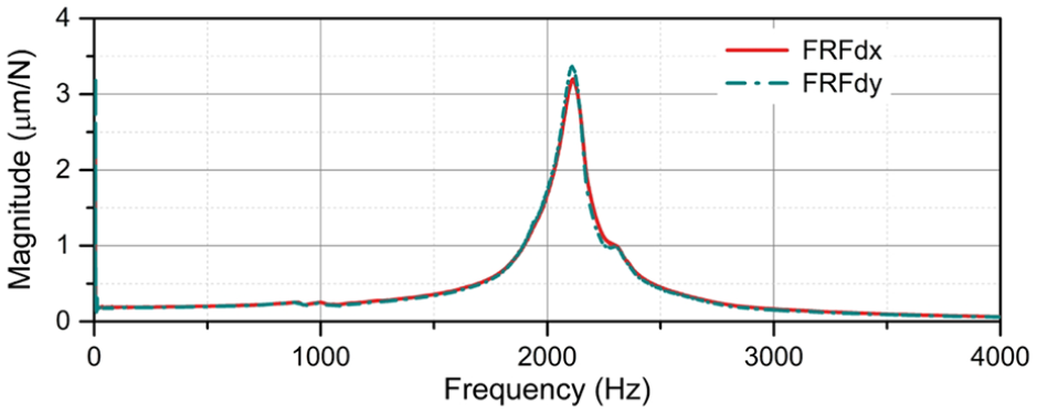
Measured FRFs of the milling tool.
Modal parameters of milling tool.
To evaluate the effect of the milling tool on the stability of the milling system, the numerical integration method, which have been introduced in section “Stability analysis and chatter frequency,” is employed again to calculate the SLD for its high accuracy and efficiency.
Taking the measurement points P1 and P3 for example, the calculated results are shown in Figure 20(a) and (b). Obviously, there is no difference between the SLD of the measurement points P1 and P3 with and without the consideration of the milling tool. Therefore, the assumption which neglects the vibration of the milling tool is reasonable in this article. Moreover, according to the theory of vibration, when the stiffness of the milling tool is 10 times larger than that of the workpiece, the effect of the milling tool on milling stability can be neglected.
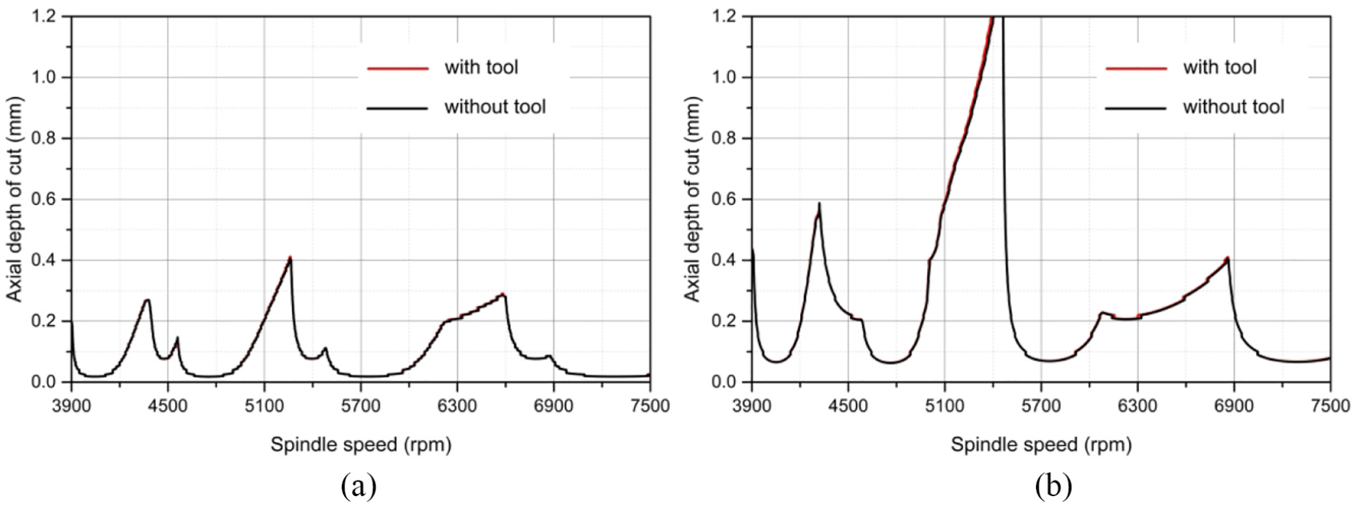
Milling stability lobes: (a) P1 and (b) P3.
Effect of structural mode on milling stability
As mentioned above, multiple structural modes of the thin-walled workpiece should be taken into consideration to study the stability of the milling system. In section “Frequency response function acquisition,” the direct FRFs of the measurement points are obtained by the impact tests, and the cutoff frequency of the impact tests is set as 3000 Hz. The test results show that there are three modes in the range of the cutoff frequency. Hence, only the first three modes are used to calculate the SLD of the thin-walled workpiece. The fourth and the higher order modes are neglected. In this section, the effect of structural mode on milling stability is investigated to provide theoretical basis for the selection of the cutoff frequency.
The fourth-order and the higher order modal parameters of the thin-walled workpiece can be also obtained by the impact test with a lager cutoff frequency. For example, the fourth-order modal frequency of the measurement point P1 is
Then the SLD of the thin-walled workpiece in the measurement point P1 can be calculated with different structural modes, as shown in Figure 21. It is noticed that there is a significant difference among the SLD with the first mode, the first two modes and the first three modes. But the SLD with the first three modes and the first four modes are identical. Hence the fourth-order and the higher order structural modes have no influence on the SLD of the thin-walled workpiece in this article.
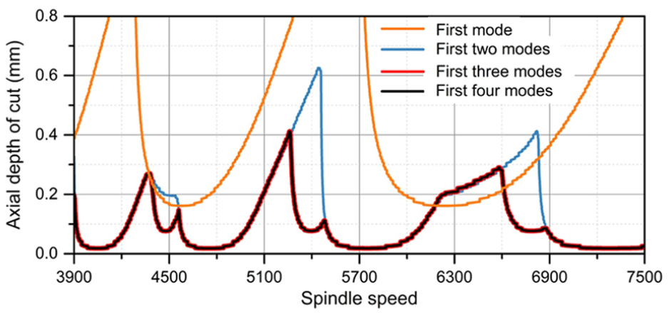
Milling stability lobes with different modes.
Therefore, the cutoff frequency should be carefully chosen to reduce the truncation error of the mode superposition method. Generally, the cutoff frequency should be at least 6 times of the exciting frequency.
Conclusion
The dynamic behavior of the thin-walled workpiece with multiple structural modes in the milling process is studied in this article. A complete cantilever plate model is proposed, and the numerical integration method is employed and extended to thin-walled workpiece milling process. In the meantime, the variations of the thin-walled workpiece dynamic characteristics caused by the tool position are considered. The stability limits are achieved, and a clear picture about the chatter frequency arising in thin-walled workpiece milling process is given. Then, the responsible structural mode for the instability of the milling process is identified. Moreover, the mechanism of the interaction of multiple structural modes when the thin-walled milling chatter occurs is revealed. The predicted results are verified by a series of milling tests, which could provide a theoretical basis for the active control of the thin-walled workpiece milling chatter. Finally, the effects of milling tool and structural modes on milling stability are discussed separately, which could provide theoretical basis for the neglect of milling tool and the selection of the cutoff frequency.
Footnotes
Declaration of conflicting interests
The author(s) declared no potential conflicts of interest with respect to the research, authorship, and/or publication of this article.
Funding
The author(s) disclosed receipt of the following financial support for the research, authorship, and/or publication of this article: This research was supported by the Natural Science Basic Research Program of Shaanxi (No. 2020JQ-183), National Science and Technology Major Project of China (No. 2018ZX04005001), Fundamental Research Funds for the Central Universities (No. 31020190502007), and Shaanxi Key Research and Development Project (Grant No. 2019KW-018).