
Abstract
To enhance the environmental adaptability of the quadruped robot and realize its stability in terrain with obstacles, this paper studies the fusion of sensor information feedback and bio-reflection control algorithm. First, a central pattern generator (CPG) that generates basal rhythmic movements is constructed. Secondly, a simplified foot end that can be used to identify the touchdown and obstacle information is designed. To enhance the stability of the quadruped robot during the flexor reflex process and avoid the problem of solidification in the reflex process, the foot touch signal was introduced into the flexor reflex algorithm, which enhanced the flexibility of the reflex process. To avoid secondary collisions with obstacles, the postswing reflection process is optimized, and active obstacle avoidance is realized after the obstacle is touched. Finally, the organic fusion of sensor information feedback, CPG control network, and bio-reflection control algorithm is realized. The simulation results show that the robot’s ability to overcome obstacles is improved, the number of reflections is less, and the reflection process is more stable.
Introduction
In recent years, quadruped robot motion control in complex terrain has become a hot topic.1–3 In the face of unstructured terrain, footed robots have stronger environmental adaptability than crawlers and wheeled robots. Additionally, quadruped robots are more stable than bipeds and simpler than hexapods. There are many control methods for quadruped robots.4–8 Among them, the combination of CPG9–11 and biological reflection control algorithm can make the robot move more stably in complex terrain. However, the current common biological reflex process is fixed, and it is difficult for robots to adapt to complex and changeable environments. This paper focuses on the research of flexor reflex, and integrates the sensor information into the bio-reflection algorithm12-14 so that the robot can flexibly change the reflection process according to the sensor information during the reflection process, so that it can obtain better stability.
By processing the feedback of sensing information, the combination of bioreflection and CPG can greatly improve the environmental adaptability of the robot, and many scholars have also made a lot of contributions in this field and provided valuable experience. Sun et al. 15 proposed a novel distributed force feedback-based reflex with online learning (DFRL), which integrates force-sensing feedback, and reflexes, and cooperates with CPGs through learning to generate adaptive motion commands. Literature 16 modified the proposed reflex model according to the special configuration of quadruped robot joints and trot gait patterns. The simulation results show that the proposed CPG controller with vestibular reflex function has higher control efficiency and stability for the quadruped robot trotting on the slope. Luo et al. 17 proposed a control scheme combining CPG and lateral step reflection. It used ZMP theory and introduced an inverted pendulum model to predict the step length and times required for a lateral step of a quadruped robot. Simulation results showed that its ability to resist lateral impact was significantly improved. Duan et al. 18 fused CPG with a flexor reflex model, and used threshold segmentation method to identify hard and soft obstacles in terrain with the help of foot force feedback, and verified the adaptability of the robot to multi-obstacle terrain through simulation. However, this reflex process was fixed and could not change flexibly according to feedback information during the reflection process. With sensor technology development, CPG fusion control and bioreflection algorithms and multisensors will continue to develop, 19 and quadruped robot adaptability to complex environments will also be improved.
Quadruped robot model and CPG control network construction
Quadruped robot model
The MQ quadruped robot is the research object, and its three-dimensional model is shown in Figure 1(a), and the real object is shown in Figure. 1(b). The driving method of the robot is electric, which adopts the configuration of the front elbow and back knee. Each leg has three degrees of freedom, including the knee joint, hip joint, and side swing joint. The parallelogram and antiparallelogram are introduced in the leg structure design for power transmission, and the hip joint motor and knee joint motor is integrated into the inside of the side swing joint of the fuselage.
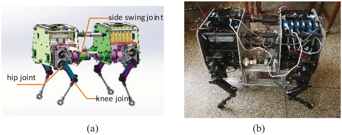
MQ quadruped robot: (a) MQ robot model and (b) MQ robot prototype.
CPG mathematical model
According to biological principles, the control system of animals to generate rhythmic movements is hierarchical and modular, and CPG is a low-level neural center that can accept active regulation by high-level neural networks and passive biological reflexes based on sensory information. These reflex actions ensure that the body remains stable under a sudden passive stress state, and at the same time, the command of the advanced nerve center gives the body the ability to avoid danger actively.
Oscillator
The oscillator is the basic unit of the CPG control network, and there are two common types: neuron oscillators and nonlinear oscillators. Matsuoka and Kimura are two common types of neuron oscillator models. Although these two oscillators have clear bionic meanings, their dynamic characteristics are relatively more complex and there are many parameters. The other type is nonlinear oscillators, which have relatively few parameters and mature models, such as Kuramoto and Hopf oscillators. In this paper, the Hopf oscillator is used as the basic unit to build the CPG model of the nonlinear oscillator. The mathematical model of the Hopf oscillator is as follows:
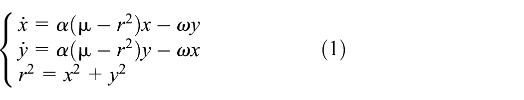
In the above formula,
In the above formula,
CPG control network
The CPG multi-degree-of-freedom coupling in this paper is a network structure that uses four oscillators, each of which outputs signals from the hip and knee joints of one leg. The mathematical model of the CPG network topology is shown in formula (3):

In formula (4),

Intrafoot coupling
The CPG control network topology consists of four oscillators. Each oscillator generates two signals through the coupling matrix, which can be used for hip joint and knee joint control. The state signal generated by a single oscillator cannot be used directly as a robot knee. The joint rotation signal can be used for knee joint control only after intrafoot coordination transformation. During the swing phase, the knee and hip joints move at the same time, while the knee joint remains unchanged during the support phase. The knee joint signal can be obtained by formula (6). The swing amplitude, leg-lift height, and step length of the knee joint can be adjusted, and the knee joint angle can be kept unchanged during the support phase according to the conditions.
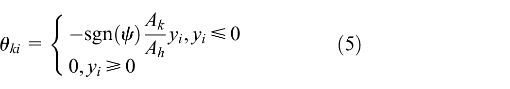
Among these parameters,

In formula (6),

Motion diagram of a single quadruped robot leg.
Fusion of bioreflex and CPG networks
The block diagram of the control system model based on CPG, the bioreflection control algorithm, and multisensor fusion is shown in Figure 3. Additionally, through the feedback of the touchdown and obstacle touch signals of the foot sensor, the quadruped robot performs the corresponding flexor reflex behavior according to the feedback information, and the joint signal returns to the normal CPG control signal after the reflex is completed. Through multisensor information feedback, the biological reflection algorithm is organically combined with the CPG control network, which greatly improves the robot’s ability to perceive and adapt to the environment and realizes the adaptive control of the interaction between the quadruped robot and the environment.
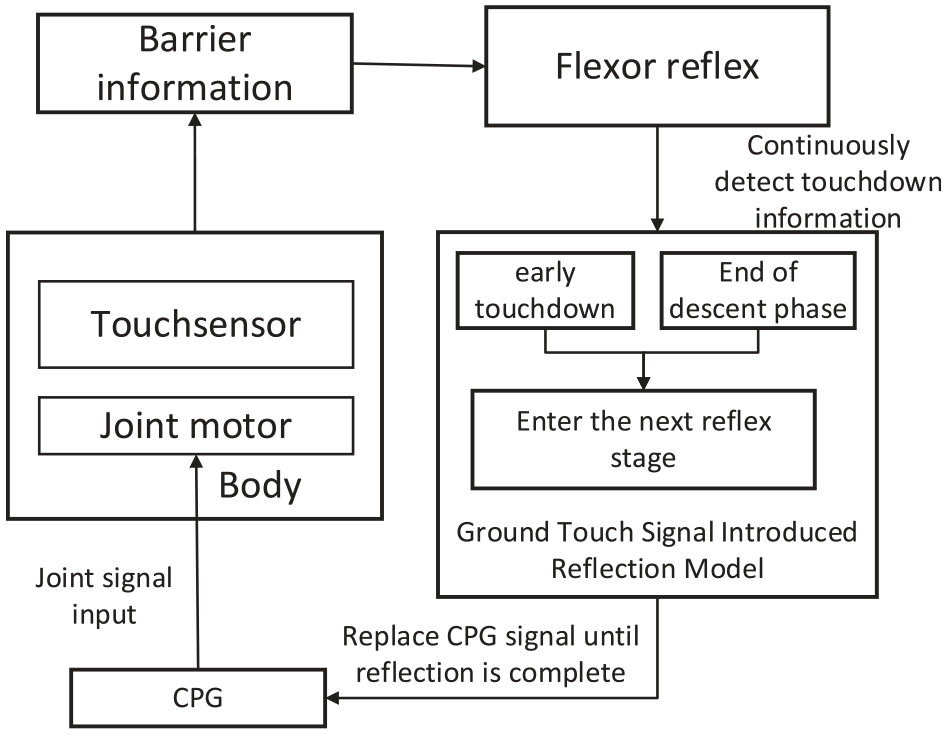
Control System.
Flexor reflex
Principle and process of the flexor reflex
The flexor reflex is the rapid contraction of the flexor muscles and relaxation of the extensor muscles by the organism after the limb is stimulated to release the limb from the noxious stimulus. When the flexor reflex is applied to the quadruped robot, after the lower leg segment of the normal walking robot touches the obstacle, the corresponding leg will perform the obstacle-crossing action. When a leg hits an obstacle, as shown in Figure 4, the reflex action is divided into four steps. Each step is a movement from the solid line to the dashed line. The specific process is as follows: (1) Swing the knees back to avoid obstacles; (2) Swing your knees up and your hips back so your feet are higher than the obstacle; (3) Swing your hips forward, keeping your knees in place; (4) Swing your knees down so your feet can land smoothly.

Obstacle crossing process of the flexor reflex.
The quadruped robot has different reflex processes in different movement stages and joint configurations. According to the time of touching the obstacle, the flexor reflex is divided into the preswing phase and the postswing phase reflex. The reflection in the postswing phase is because the remaining reflection time is less than 1/4 of the swing period, so the obstacle crossing is abandoned, and the action shown in Figure 4(1) is performed.
The principle and modeling of the foot
In nature, the feet of quadruped mammals are capable of multidirectional sensing. They can sense terrain, including obstacles, by touch, and triggering the flexor reflex also requires touching specific foot locations. We divide the feedback signals of the foot into obstacle touch signals and ground touch signals. As shown in Figure 5, there are touch sensors at three locations on the foot. A and C simulate the front and rear of the foot, providing touch barrier feedback, and B simulates the bottom end of the foot. When simulating in Webots, set the configuration of the contact sensor to bumper. During normal walking, generally, only the B sensor placed on the foot has ground signal feedback.
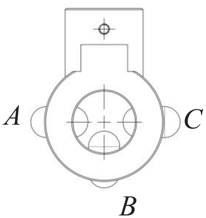
Simplified foot.
Based on the above design concept and modeling, we refer to the original algorithm in Li 20 to optimize the reflex process, we introduce the touchdown signal into the flexor reflex control algorithm, and optimize the reflex process in the postswing phase.
Mathematical model of the flexor reflex
This paper mainly studies the flexor reflex of the elbow joint leg structure.
Mathematical model of the preswing phase reflex
In the original algorithm, when the preswing period reflex occurs, the reflex leg needs to complete all the stages shown in Figure 4 in the current remaining reflex cycle. Each leg swings at a fixed angle according to the program setting. When the remaining reflection time is a critical value, the speed and acceleration generated by the joints are very large.
The mathematical model of the original algorithm is shown below:

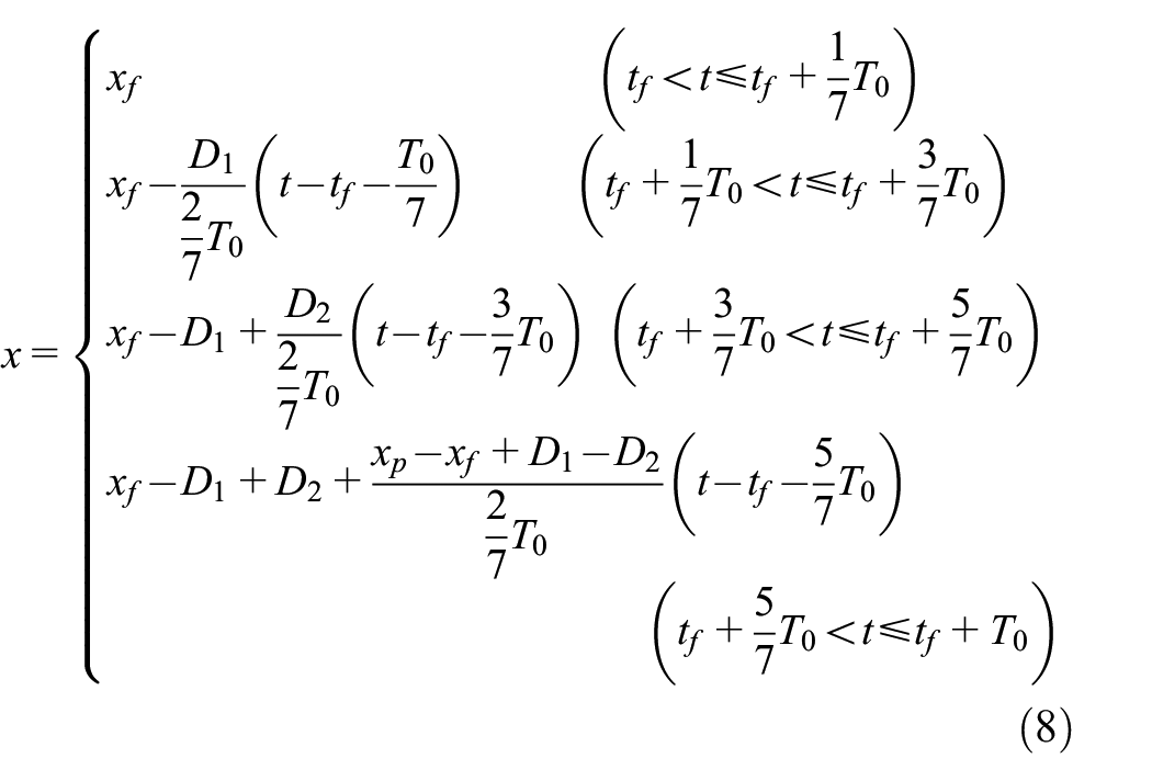
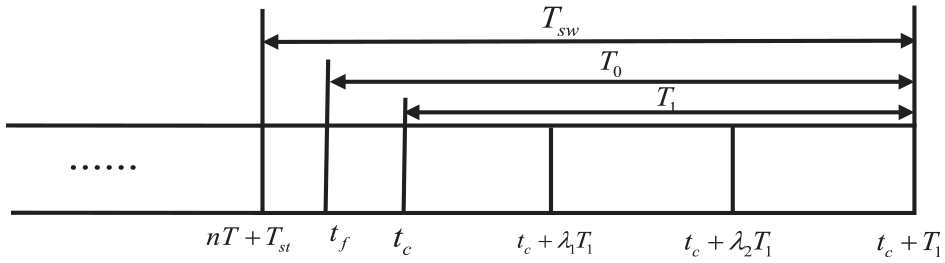
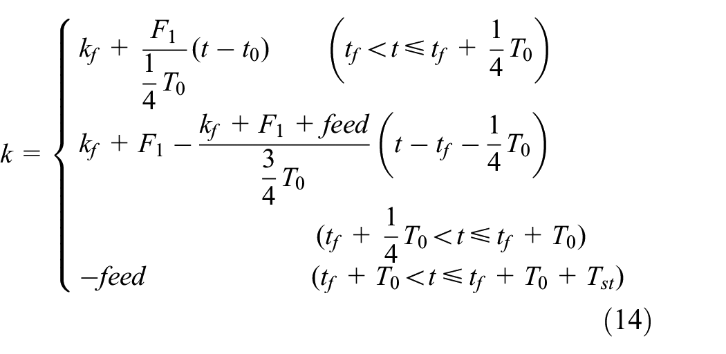
To optimize the reflection process and make the moving process more flexible, the touchdown signal is introduced into the algorithm, and the reflection leg automatically advances to the next reflection stage after receiving the real-time ground contact status feedback from the B sensor. After the reflex leg receives the real-time touchdown status feedback from the B sensor, it automatically advances to the next reflex stage, and the remaining reflex stage has more time, which can reduce the joint speed and make the moving process more flexible. The mathematical model of the preswing phase reflection optimization with the introduction of the touchdown signal is as follows:


where
The phase diagram of preswing reflection.
where


To prevent sudden changes in speed and acceleration, the first stage of reflection is to set the knee joint to move at a fixed speed during the backswing process and to calculate a more reasonable v. Considering the difficulty of generating the touchdown signal and the peak commutation angle, the maximum swing angle generated by the first t/2 period of the swing phase is set to 8°.

During the reflex movement, there may not necessarily be touchdown signal feedback, especially when the height of the leg is high, and to ensure that the next reflection stage is entered at the specified time, if there is still no touchdown signal feedback after
Mathematical model parameters of elbow structure flexor reflex.

Mathematical model of the postswing phase reflex
In the original control algorithm of postswing phase reflex, since the current remaining reflection time is less than 1/4 cycle, the reflex leg swings back to the support position and abandons obstacle crossing. The mathematical model is as follows:

If the height of the obstacle is higher than the maximum height of the feet off the ground, the robot will touch the obstacle twice and continue over the obstacle by reflex. Obviously, this behavior is unnecessary and detrimental to the motion stability of the robot. Since it is known that there are obstacles ahead, in order to make the whole reflex process more intelligent, the legs of the quadruped robot receiving the feedback information from the sensors should actively cross the obstacles in the next leg-raising stage. Therefore, we optimized the entire reflection process to have the ability to overcome obstacles actively. The optimized mathematical model of the reflection process is as follows:

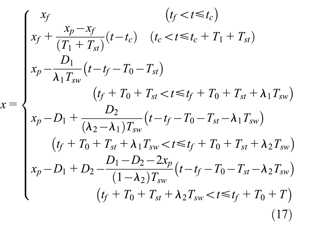
Where

As with the preswing phase reflex, to prevent the inability to enter the next phase because the foot end did not touch the ground, we set the maximum value of

Phase diagram of the postswing phase reflex.
Simulation
The correctness of the mathematical model proposed above is verified in Webots. Set the basicTimeSteps in Webots to 16.
Obstacle crossing motion simulation experiment
In the simulation, the trotting stance was used to verify the flexor reflex movements of the elbow-structured leg during the postswing and preswing phases. The maximum leg lift height h in formula (6) is set to 0.028 m. Set the obstacle height in Webots to 0.068 m (after many simulation tests, the original algorithm can cross obstacles below 0.065 m).
Simulation of the preswing phase reflex
Since the height of the raised leg is higher when the preswing phase reflex occurs, it was difficult to trigger the touchdown signal, so we found that in Figures 8 and 9, each reflection process takes the same time. Figure 9 shows that the left front leg starts to enter the swing phase at 4 s, and during the swing of the knee joint, the preswing reflex is triggered at 4.35 s. The knee joint quickly swings back to avoid obstacles. At 4.4 s, the reflex enters the next phase. The hip joint swings back, and the knee joint swings up so that the end of the foot is higher than the obstacle. At 4.62 s, the knee joint remains unchanged, and the hip joint swings forward for obstacle crossing. At 4.81 s, the knee joint swings down and looks for a support point. At 5 s, the movement of the preswing phase reflex is completed, and then it is converted with the CPG control signal to enter the normal movement state.
The joint curve of the original algorithm of the preswing phase reflex.

The joint curve of the optimized algorithm of the preswing phase reflex.
As shown in Table 2, the maximum knee swing angle of the robot after the optimization of the reflex process is 0.43 rad, while the angle in the original algorithm is 0.29 rad, and the robot has a second reflex at 6.17 s.
Comparison of preswing phase reflex.

Figures 10 and 11 show the detailed process of the preswing phase reflex, where Figure 10 shows the reflection not optimized, and the figure shows that after multiple reflections, the obstacle is still not passed. No matter how long the remaining reflex time is, the knee joint needs to swing down to a fixed angle, so the sudden change of speed, in this case, is unavoidable. When the remaining reflex time is at a critical value, according to the parameter settings, we can theoretically calculate the maximum swing speed of the knee joint to be 3.91 rad/s, so we need to avoid sudden changes in speed and acceleration. As shown in Figure 11, after optimization, the knee joint swings down at the speed of v1 in the first reflex stage, and the reflex will not enter the next reflex stage until it hits an obstacle or exceeds the maximum reflex time of this stage. This strategy addresses the grounding that occurs when the knee swings back. However, since the leg in the preswing phase reflex is in the lifting stage, the height of the raised leg is generally high, and it is difficult to trigger the touchdown signal when the knee joint is retracted.

The preswing phase reflex with the original algorithm.

The preswing phase reflex with the optimized algorithm.
Figure 12 is a screenshot of the simulation in Webots. As shown in Figure 12(a), the left front leg of the robot touches an obstacle when it swings. Sensor A or B in Figure 5 feeds back the obstacle-touching signal to the quadruped robot, and the robot starts to perform the corresponding reflection action. Similar to the moving process in Figure 4.
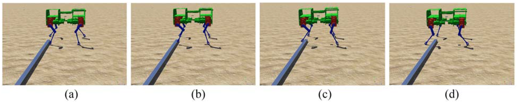
Process of preswing phase reflex in Webots: (a) the knee joint touches the obstacle during the forward swing, (b) the knee joint swings back to avoid the obstacle, (c) the hip joint swings forward to cross the obstacle, and (d) the reflex leg touches the ground for support.
Figure 13 is a comparison of Euler angles for the two cases. Figure 19(a) shows the yaw angle measured under exactly the same parametric simulation conditions. The robot with optimized reflex process successfully crossed the obstacle at 4.35 s. However, because the raised height of the robot’s reflex leg in the original algorithm was lower than the obstacle, multiple crossings were unsuccessful, and a yaw angle of 0.79 rad was generated at the 10th second. Figure 13(b) and 13(c) are the measured roll angle and pitch angle, respectively. It can be found that within a few seconds after the reflection occurs, multiple reflections are additionally triggered in the simulation with the unoptimized algorithm.

Comparison of Euler angles of the body during the preswing phase reflex: (a) ψ-pitch angle, (b) ϕ-roll angle, and (c) θ-pitch angle.
Figure 14 is a displacement diagram of the robot’s center of mass in the horizontal direction. The robot, after the optimization of the reflection process, passed the obstacle smoothly, while the original algorithm could not walk forward normally after the reflection occurred at 4.35 s, and their horizontal displacements at the 10th second are 0.9 and 1.14 m, respectively.
The trajectory of the center of mass in the vertical direction.
Simulation of postswing phase reflex
In the original algorithm, after triggering the swing retroreflection, the knee joint swings back to find the support point and gives up crossing the obstacle in the current cycle, as shown in Figure 4(1). This algorithm faces two situations:
In one case, if the height of the obstacle is lower than the height of the raised leg, the robot can directly cross the obstacle in the next swing cycle, and its joint curve is shown in Figure 15(a). In the second case, if the obstacle height is higher than the maximum leg lift, the reflex leg will touch the obstacle twice during the swing phase, and its joint change curve is shown in Figure 15(b).

The joint curve of the phasic reflex of the swing: (a) the joint curve of a single reflex, (b) the joint curve of multiple reflections, (c) the joint curves for oscillating retroreflection with the optimized algorithm.
In response to the above problems, we changed the process of postswing phase reflex. The simulated joint curve is shown in Figure 15(c), and it can be found that the reflex leg directly crosses the obstacle in the next swing cycle after the reflex at the postswing phase. This process only touches the obstacle once, and the impact between the foot end and the ground is reduced due to the introduction of the touchdown signal.
Figure 16 is a detailed analysis diagram of the movement process of the reflex leg under the above three comparison cases, in which tc in Figure 16(c) represents the moment when the foot touches the ground, and tf represents the moment when the foot touches the obstacle. Figure 16(a) shows that the knee joint touches the obstacle in 2.89 s, and the joint quickly swings back to a fixed angle in the remaining reflex time. Since the robot cannot perceive the grounding information of the foot end during the reflection process, the knee joint continues to swing, thus increasing the impact force between the foot end and the ground.

Detailed reflection process of the postswing flexor reflex: (a) joint curve of a single reflection, (b) joint curves for multiple reflections, and (c) joint curves with the optimized algorithm.
As shown in Figure 16(b), unlike the previous situation, the robot triggers the preswing phase reflex at 4.45 s after completing the first postswing phase reflex, and the foot touches the obstacle twice during the whole process. We can find that the hip joint and knee joint remain unchanged when the foot end is supported on the ground in 2.84–4 s, which is actually not conducive to the inertial force of the body to move forward.
Figure 16(c) is the joint motion curve after optimization of the reflection process. The postswing phase flexor reflex is triggered at 2.89 s, the knee joint swings back and touches the ground at 2.97 s, and the knee joint stops moving immediately after sensing the ground, and support remains unchanged. The support phase ended in the 4th second, and then the robot directly performed the obstacle-crossing movement. At 5 s, the entire swing postphase flexor reflex process is completed.
Figure 17 is a screenshot of the simulation process of the algorithm-optimized flexor reflex in Webots. This process combines the reflections of the preswing phase.

Swing postphase simulation process in Webots: (a) the knee joint swings back after touching the barrier, (b) the knee joint remains unchanged in the support phase until the foot touches the ground, (c) the hips swing back, and the knees swing forward to avoid obstacles and raise the leg height, (d) the swings forward and crosses the obstacle with the inertia of the forward movement of the body, (e) the reflex leg lands and remains supported, and (f) the reflex is completed.
Figure 18 shows the comparison of Euler angles after optimization and the original algorithm.

Comparison of Euler angles of the body during postswing phase reflex: (a) ψ-pitch angle, (b) ϕ-roll angle, and (c) θ-pitch angle.
It can be found that the reflection of the postswing phase reflex occurs at 2.89 s. Figure 18(a) shows the measured yaw angle, in which the robot with the optimized algorithm crosses the obstacle naturally and smoothly and only produces a yaw angle of 0.056 rad at 10 s. In the simulation of the original algorithm, the reflex legs of the robot collided with the ground and slipped during the backward swing. At the same time, the robot reflects again in 4.45 s; however, because the preswing phase reflex algorithm is not optimized, the robot fails to successfully cross the obstacle, which is also why the obstacle is touched multiple times. It can also be found from Figures 18(b) and (c) that due to the occurrence of multiple reflections, the pitch angle, and roll angle of the body fluctuate irregularly, which is not conducive to the stability of the robot’s motion.
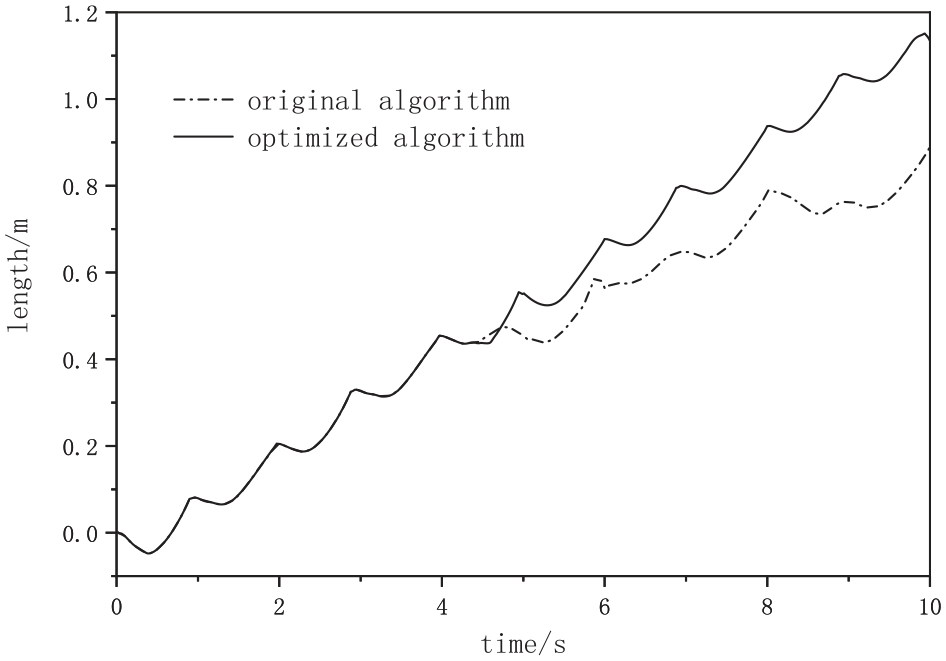
Figure 19 is the displacement diagram of the robot’s center of mass in the horizontal direction. The robot reflects at 2.89 s, and in the simulation with the original algorithm, the body shifts laterally and fails to cross the obstacle, and finally it produces a horizontal displacement of 0.88 m at the 10th second. In comparison, the robot with algorithm optimization successfully crossed the obstacle and produced a horizontal displacement of 1.15 m.

Displacement of the center of mass in the horizontal direction.
To verify that the contact force between the foot end and the ground during the reflection process is reduced after the optimization of the algorithm, we set touch sensor B to force mode. Figure 20(a) and (b) show the foot impact force of the original algorithm and the optimized algorithm in the reflection process, respectively. The results show that the collision between the foot end and the ground produces a force of up to 1150 N when there is no feedback of the foot end touchdown signal in the algorithm, and the maximum force in the optimized algorithm does not exceed 450 N. This result proves that the introduction of the foot touch signal into the control algorithm can effectively improve the reflex compliance of the robot and reduce the rigid impact between the foot and the ground.

Contact force between the foot and the ground: (a) original algorithm and (b) optimized algorithm.
Finally, Table 3 can be obtained. After optimizing the reflection process algorithm, the robot can autonomously overcome obstacles, and can judge the movement of the next stage in real-time according to the touchdown information. After optimization, the number of reflections required is reduced, and the robot can successfully cross obstacles, and the collision force generated is less than 1/2 of the unoptimized.
Comparison of postswing phase reflex.

Conclusion
To realize the flexor reflex of the quadruped robot, the foot touch signal was introduced into the algorithm with the help of a foot sensor, which enhances movement flexibility. In order to avoid secondary contact with obstacles, the reflection process of the postswing phase is optimized, so that the whole moving process is smoother and more stable, and the adaptive obstacle crossing of the robot is realized.
Aiming at the curing problem of the flexor reflex process of the quadruped robot, we introduced the touchdown information into the flexor reflex algorithm, which can judge the state according to the sensor information feedback in real-time and execute the corresponding reflex, so that the reflex of the robot is more stable.
To enhance the robot’s environmental perception ability, the relative position information of the obstacle and the foot end is judged by the foot sensor, and then the corresponding flexor reflex movement can be performed according to the feedback information.
Footnotes
Acknowledgements
This work has been supported by provincial key research platforms such as Yunnan Provincial Key Laboratory of Advanced Equipment Intelligent Manufacturing Technology and Yunnan Provincial University Industrial Robot Technology Engineering Research Center.
Handling Editor: Chenhui Liang
Author contributions
This paper has four authors and their names and contributions to the paper are: MC (writing and preparation of original draft), XM (writing, reviewing, and editing the whole paper), SW (editing and helping with the revisions), and YZ (editing and helping with the revisions).
Declaration of conflicting interests
The author(s) declared no potential conflicts of interest with respect to the research, authorship, and/or publication of this article.
Funding
The author(s) received no financial support for the research, authorship, and/or publication of this article.
Data Availability
The datasets logged and/or analyzed during the current study are available from the authors on reasonable request.