
Abstract
The cutting tooth density of the toroidal worm wheel hob affects the quality of the hobbed worm wheel surface. The more the number of the cutting teeth, the higher the accuracy of the hobbed worm wheel surfaces. However, if the tooth density is greater, it’s easier to cause the grinding wheel to interference with other cutting teeth when grinding the relief surfaces, and the structure of the adjacent cutting teeth will be damaged. Therefore, this paper studies the checking method of grinding interference of relief surfaces, and then puts forward a design method of the maximum cutting tooth density to avoid grinding interference. Based on the point contact generation method, a relief grinding method of the toroidal worm wheel hob is proposed, and the grinding motion model is established. By analyzing the grinding processes of each relief surface, the variation law of grinding interference is obtained, and the relief grinding checking method is established based on the defined interference angles. The maximum interference position is determined, and the maximum number of the cutting tooth to avoid grinding interference is obtained. The study provides the key theoretical basis for the precision manufacturing of the high-density complex toroidal worm wheel hob.
Keywords
Introduction
The double enveloping toroidal worm drive has the characteristics of multi-tooth and double-lines contact, and it has the advantages such as strong bearing capacity, good lubrication performance, and high efficiency.1–3 Theoretically, the surfaces of the worm wheel is generated by the helical surfaces of the worm.4–6 Different methods have been carried out to machining worm wheels, such as fly cutting, worm grinding, and hobbing. Zhou et al. 7 and Tang et al. 8 have built the method for precision machining the face gear by worm grinding, including worm dressing, geometric error compensation, and measurement. In actual, the tooth surface of the worm wheel is hobbed by a worm wheel hob which is manufactured based on the worm.9,10 The worm wheel tooth surface hobbed by the toroidal worm wheel hob includes contact areas and transition areas. 11 The contact areas are the meshing contact areas of the toroidal worm pair, and the transition area does not participate in the contact.12,13 Polowniak et al. 14 have built a new calculating method of the worm wheel with different cutting edges profiles of the hob, such as a rectilinear tooth axial profile and an arc (concave and convex) tooth axial profile. The toroidal worm wheel hob has the characteristics of variable tooth thickness, variable tooth shape, and variable helix angle.15–17 Based on the throat helix angle, Yang et al. 18 has provided a method for generating the spiral rake faces of the planner enveloping toroidal worm wheel hob with multiple helixes, where the spiral rake face is machined by a cylindrical generating surface. Liu et al. 19 provides a relief grinding method for the planner double-enveloping worm wheel hob by a plane grinding wheel, and the land width and relief angle on the land edge can be precise obtained. Rui et al. 20 select the dual-cone grinding wheel to grind the relief surface of the toroidal worm wheel hob with spiral rake faces. Since both sides of the dual-cone grinding wheel are generating surfaces, the direction change adjustment of the grinding wheel can be avoided when the dual-cone grinding wheel grinds the relief surfaces on the left and right sides. If the parameters of the grinding wheel change, the shape of the relief surface will be change too.
The design parameters of the worm wheel hob is mainly effecting the quality of worm wheel’s surfaces, such as the tooth number, rake angle, and relief surface.21,22 In order to obtain the meshing quality of the manufactured face gear, Wang et al. 23 provided an effective measurement strategy based on sensitivity analysis, and the equation of meshing is simplified to reduce its nonlinearity and realize the digital tooth contact analysis. Aiming to address the high nonlinearity in the general equation of meshing to face gear drives, Lu et al. 24 provided a two-variable optimization model and algorithm for calculating the contact path. For the toroidal worm pair, the worm wheel’s surfaces quality can be improved by increasing the cutting tooth number of the toroidal worm wheel hob. If the cutting tooth is too more, the cutting tooth of the hob may be damaged by the grinding wheel when grinding the relief surfaces. In order to avoid the collision between the relief grinding wheel and the cutting teeth, the interference checking is required before the relief grinding of the hob. The methods of grinding interference checking usually include three categories, such as drawing method, trial grinding method, and analytical method. Based on the wheel diameter, Tian and Zheng 25 provides a method to determine whether grinding interference occurs by combining the drawing method and the analytical method, and a method to determine the grinding wheel diameter to avoid the interference of relief grinding is established. Wang 26 has studied the solution of the maximum grinding wheel radius required for the relief grinding, and the algorithm of the allowable minimum value of the grinding wheel is given on the premise of ensuring the relief grinding length of the tooth back and the interference of the grinding wheel with the next cutting tooth. Zhang 27 has studied the interference of the cutting tooth in grinding. The conical grinding wheel is simplified as a cone, and the cutting tool is simplified as a cylinder. As long as the intersection line between them does not intersect with the spiral line of the cylinder, there will be no interference. Wang and Zhang 28 have obtained the influence between the outside diameter of the grinding wheel on the relief grinding of a form milling cutter. The required grinding wheel radius can be quickly obtained by combining the drawing method with the analytical method. Li et al. 29 have used the computer aided design method to analyze the grinding interference of the hob, and the maximum and minimum allowable values of a grinding wheel are obtained.
The drawing method and trial grinding method are mainly used for checking the relief grinding interference of the cylindrical hob. These two methods are not only time-consuming, but also have a great approximate. The tooth profile of each cutting tooth of the toroidal worm wheel hob is different, and its interference checking is more complex than that of the cylindrical hob. Therefore, this paper will carry out the research on the relief grinding interference of the toroidal worm wheel hob. By exploring the change law of the relief grinding interference, the checking method of the relief grinding interference will be built, and the design ideal of the maximum number of the cutting teeth to avoid grinding interference will be put forward too.
Grinding method of toroidal worm wheel hob’s relief surfaces
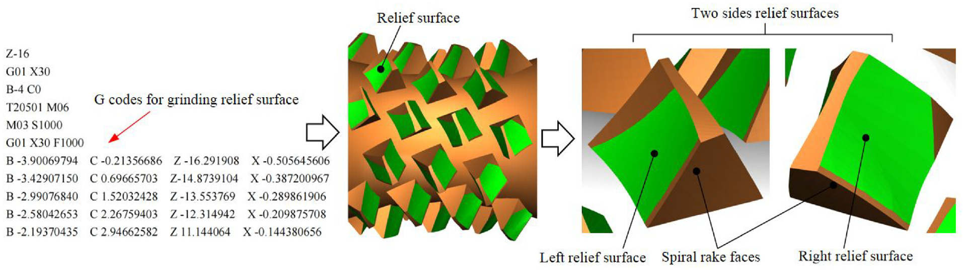
The schematic of a dual-cone double enveloping hourglass worm wheel hob is shown in Figure 1. The cutting teeth of the hob are hobbing the teeth surfaces of the worm wheel. The cutting edges are the intersections of the rake faces and the helical surfaces. The land edges are the intersections of the offset surfaces and the helical surfaces. The area between the land edges and the cutting edges are the land surfaces and they are parts of the helical surfaces. The relief surface is the part behind the land edge.

Geometry of a toroidal worm wheel hob.
The machine tool for grinding relief surface of the hob is the same as the machine tool for generating the helical surface of the toroidal worm, and the simplified model of the four-axis CNC toroidal worm machine is shown in Figure 2, which includes two linear moving axes (X, Z) and two rotating axes (B, C).

Model of the four-axis CNC toroidal worm machine.
The machining coordinate systems when grinding the relief surface with conical grinding wheel is shown in Figure 3, which includes five machining coordinate systems, such as σa (O0;

Coordinate systems for grinding relief surfaces.
Land edges coordinates and normal vector in coordinate system σo1
The land edges are the starting line of the relief surfaces, and its can be obtained by offsetting the rake face with a land width.
30
Point Pr is on the land edge, its coordinates in the coordinate system σ1 are (
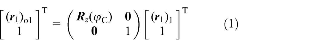
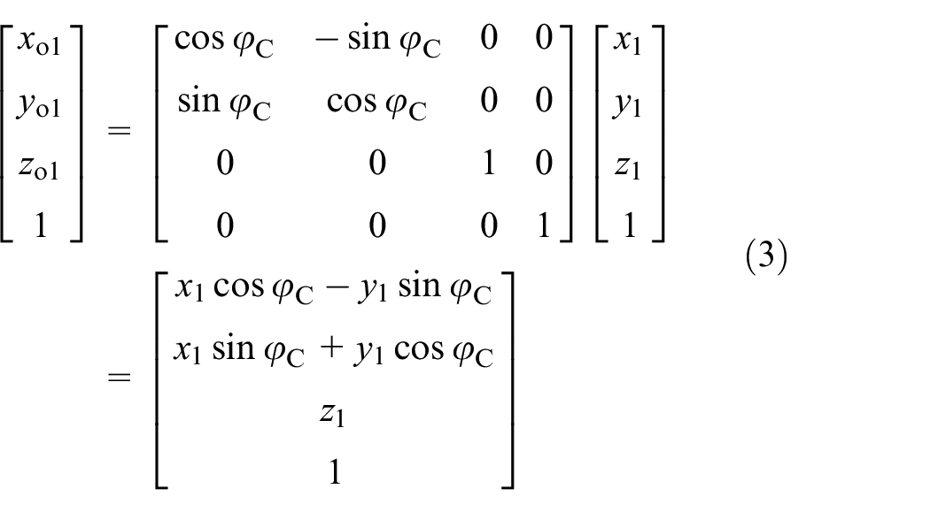
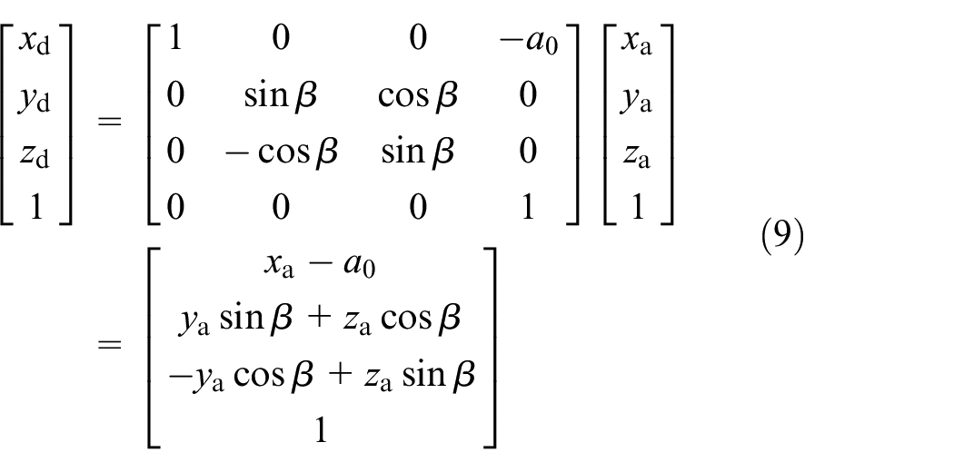
Where, the homogeneous transformation matrix from σ1 to σo1 is,
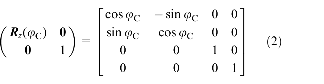
According to equations (1) and (2), the coordinates of (
(
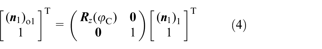
According to equations (2) and (4), the coordinates of (

Grinding wheel equations and normal vector in coordinate system σo1
A conical grinding wheel is used for grinding the relief surface of the toroidal worm wheel hob. (

In the above formula, αd and θ are the parameters of the conical surface when grinding the relief surface. The positive sign “+ ” indicates the right conical surface of the grinding wheel, and the negative sign “−” indicates the left conical surface. 31
Transforming (

In the coordinate system σd, the vector position of point O0 is expressed as

According to equations (7) and (8), the coordinates of (
The points on the conical surface translate along X and Z axes with Δa and Δc, and the points rotate around the B axis with the angle φB at the same time. Transforming (

In the coordinate system σo1, the vector position of point Od is expressed as

According to equations (10) and (11), the coordinates of (

The normal vector of the point N0 on the conical surface is (

Transforming (

According to equations (13) and (14), the coordinates of (

Relief grinding movements solving equations
When grinding the relief surfaces, the conical surface of the grinding wheel moves along the land edge by the controlling the four moving axes of the four-axis CNC toroidal worm machine.
32
In the process of relief grinding, the normal vector
Relief grinding by a conical surface.
In order to enable the grinding wheel can process each point on the relief surface, the coordinate value of the point N0 on the conical surface is equal to the coordinate value of Pr on the land edge in the coordinate system σo1,

When grinding the relief surface, the normal vector (

Then the mathematical equations for solving the movement parameters of the relief surface is as follows,

A point Pr on the land edge corresponding to a group of relief grinding parameters, and each land edge corresponds to a continuous group of relief grinding parameters (φB, φC, Δa, Δc). According to the equations (1), (2), (5), (7) and (10), the four motion parameters (φB, φC, Δa, Δc) for grinding the relief surface can be solved out. Using the solved motion parameters for programming, the relief surface can be obtained on the four-axis CNC toroidal worm machine.
Checking method for grinding interference of relief surface
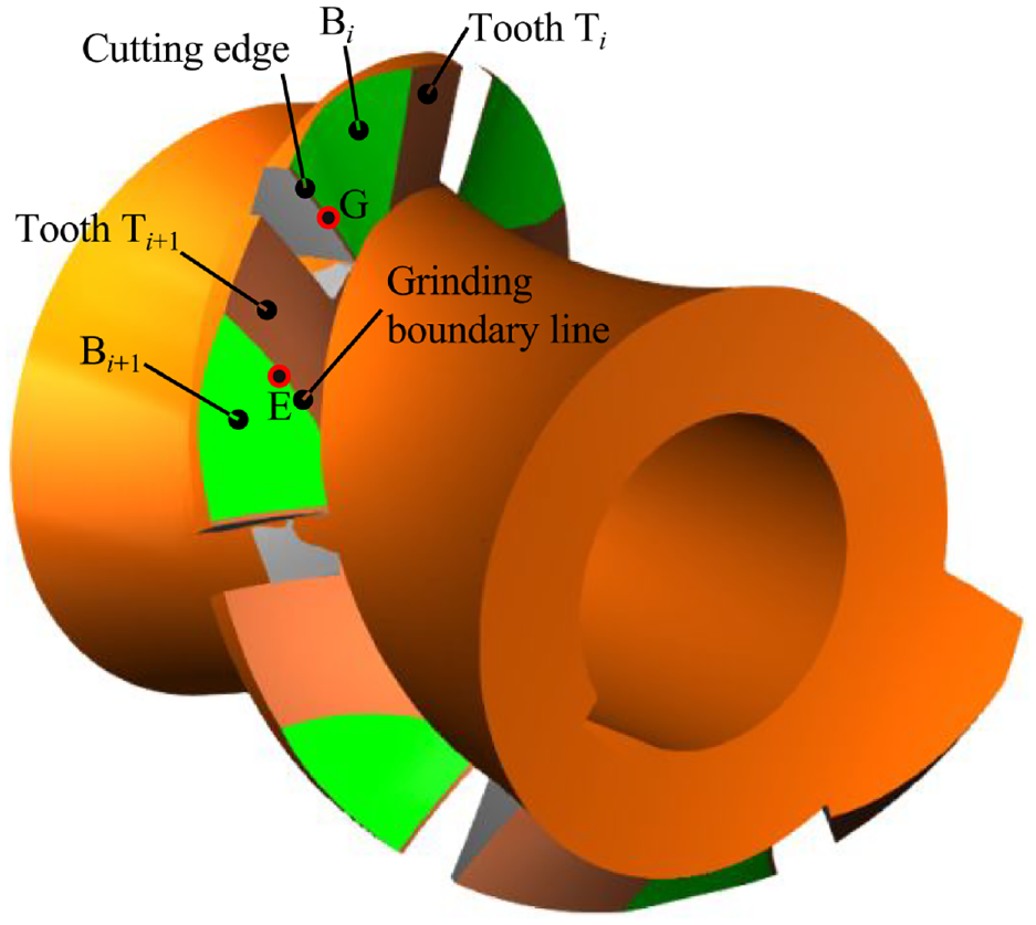
Affected by the design parameters of the hob and the parameters of the grinding wheel, the grinding wheel may interfere with the cutting teeth around the grinding wheel. The interference caused by the relief grinding is mainly concentrated on the interference caused by the next cutting tooth on the same helix. So, this paper studies the influence on the next cutting tooth. When the row number of the hob or the density of cutting teeth is increased, the grinding boundary line may cross the cutting edge of the next cutting tooth, the relief grinding interference occurs, which will make the cutting edge of the next cutting tooth damaged, as shown in Figure 5.

Relief grinding interference of toroidal worm wheel hob.
The cutting teeth on the toroidal worm wheel hob can be regarded as the circular array of cutting teeth on one helix. So, the cutting teeth on one helix of the hob are selected during the research. When the flank surfaces of the toroidal worm wheel hob are not completely machined, the relief surfaces ground by the grinding wheel intersects with the spiral surface to form two curves, as shown in Figure 6. The curve that close to the rake face is the land edge, and another is the grinding boundary line. As can be seen from Figure 6, the relief surfaces’ shape of each cutting tooth of the toroidal worm wheel hob is different with each other. When the land width and relief angle of the hob are given, the relief surface and the grinding boundary line of each cutting tooth are determined. The relief grinding interference of the cutting teeth on other helixes are the same. Views in S1 and S2 directions are established, and the number of the cutting teeth and relief surfaces are given, where Ai represents the left relief surface, Bi represents the right relief surface, and Ti represents the cutting tooth number.

Views in S1 and S2 directions on one helix of the hob.
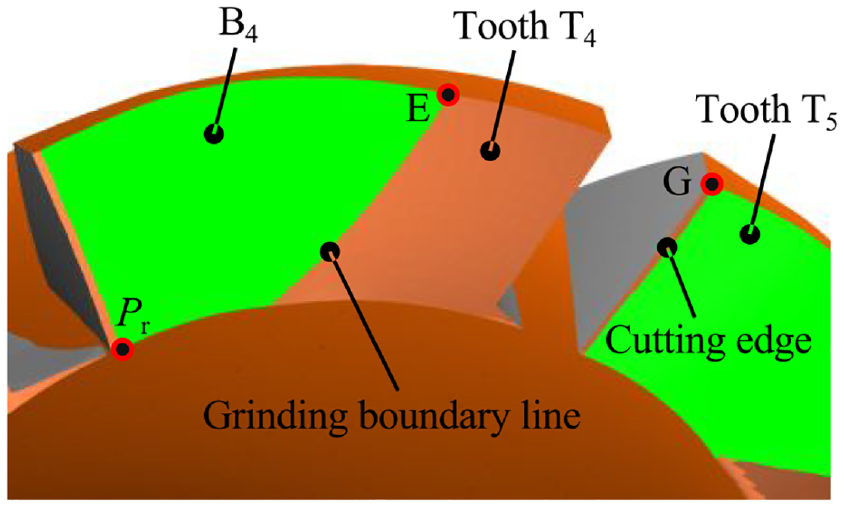
The total number of cutting teeth on one helix of the toroidal worm wheel hob is m. For any relief surface, E(xE, yE, zE) is a point on the grinding boundary line of the last cutting tooth Ti, and G (xG, yG, zG) is a point on the cutting edge of the cutting tooth Ti+1, where i = 1, 2, …, n − 1. Points E and G are located on the same torus. There is no cutting tooth behind the cutting tooth Tn, so it will not interference with any cutting tooth when grinding the relief surface of the cutting tooth Tm. The points E and G are projected into the cross section of

If calculated θi of all cutting teeth are greater than zero, it means that the point E is away from the point G and the point E is in the front of G, and there will be no grinding interference. If there are calculated θi less than or equal to zero, it means that there are points E coinciding with points G or after the points G, there will be grinding interference.
Cutting tooth density to avoid relief grinding interference
Increasing the tooth density of the worm wheel hob can make the hobbed worm wheel tooth surface closer to the theoretical tooth surface. When there are more teeth on one helix of the hob, the relief grinding interference phenomenon will occur. Among all the interference angles θi, there is a maximum interference angle θmax. Therefore, the phase angle φf between two adjacent rake faces on the same helix should be greater than the maximum interference angle θmax, so as to ensure that there will be no interference when grinding the relief surface.
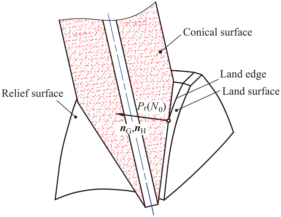
When designing the hob, it is necessary to determine the position of the throat tooth and the side teeth on both sides firstly. Figure 7 is a schematic diagram of the cutting teeth on one helix. The phase angle around the hob shaft between the rake faces of the throat cutting tooth Th and the side teeth TL and TR is φz.
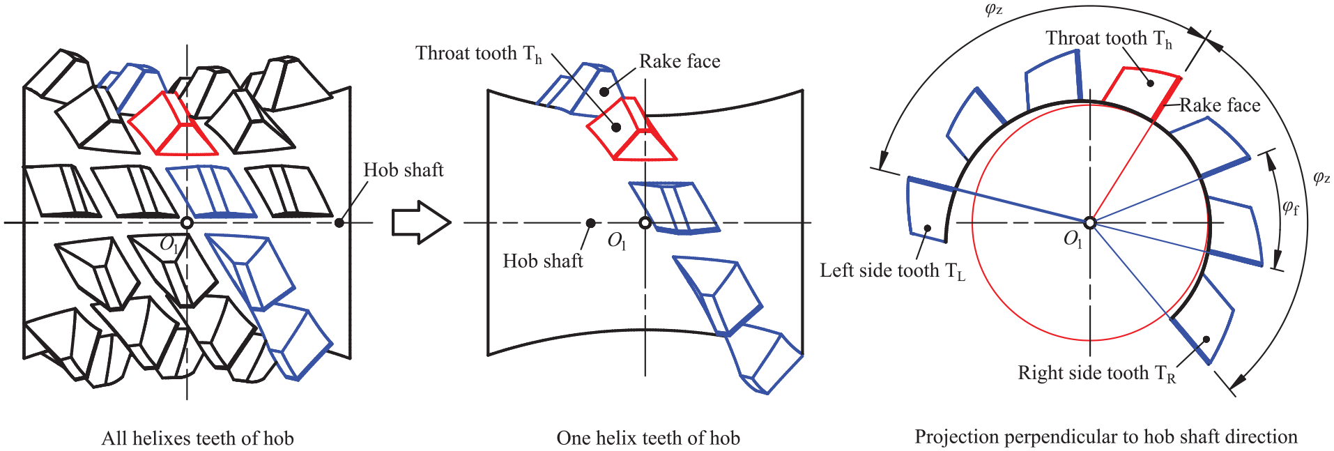
Schematic diagram of cutting teeth on one helix.
The total number of cutting teeth on one helix is n, and n is odd and greater than 3. The phase angle φf between adjacent cutting teeth can be calculated as follows,

With the increase of the number of cutting teeth n, the phase angle φf is decreasing. If φf ≤ θmax, the grinding wheel may collide with the cutting teeth and resulting in generating interference when grinding relief surfaces. The maximum number of cutting teeth to avoid grinding interference is recorded as nmax, and the number of cutting teeth n needs to be controlled within the range of 3 ≤ n ≤ nmax.
Example analysis for relief grinding interference
Based on a typical design example of a dual-cone double enveloping toroidal worm wheel hob, this part analyzes the variation law of relief grinding interference and the maximum tooth density to avoid grinding interference. The basic parameters of the hob are shown in Table 1.
Parameters of a toroidal worm wheel hob.

The theoretical worm wheel tooth surface is the envelope surface of the basic toroidal worm’s helical surface. The cutting edges of the hob tooth are only part of the curve on the helical surface of the basic worm. So, the hobbed worm wheel tooth surface is not completely consistent with the theoretical worm wheel tooth surface. The cutting teeth density of a toroidal worm hob affect the accuracy of the hobbed worm wheel tooth surface. For one cutting tooth of the hob, the swept volume is obtained when hobbing the worm wheel blank. Because the the cutting edges’ shapes of each cutting tooth on the toroidal worm wheel hob are different, it will form macro-scopically visible wave edges when hobbing the worm wheel surface, as shown in Figure 8. The height of wave edge will be reduced by increase the density of cutting teeth. Compared with three cutting teeth on one helix, the worm wheel surface can be further hobbed and trimmed by the hob with seven cutting teeth on one helix and the wave edges are increased too. But if the cutting tooth density is greater, it’s easier to cause the grinding wheel to interference with other cutting teeth when grinding the relief surfaces.
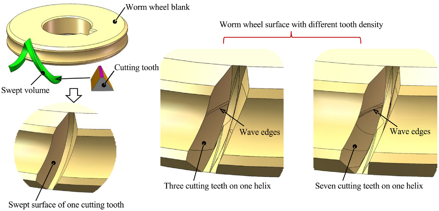
Influence of cutting tooth density on worm wheel tooth surface.
Theoretically, increasing the cutting tooth density of the hob will produce a more precise worm wheel tooth surface. However, in actual manufacturing, as the density of the cutting teeth increases, the processing difficulty also increases, which may introduce potential machining errors of the hob and lead to a decrease in the accuracy of the worm wheel tooth surface. In order to avoid the influence of the machining errors of the hob on worm wheel surface, a closed-loop manufacturing method by adjusting the machine settings need to be taken. The main process is finding out the relationship between the machine settings and the errors of the hob. It’s need to determine the adjustable machine settings firstly, such as the linear movement parameters (Δa, Δc) of the machine tool along X and Z and the rotational motion parameters (φB, φC) of the machine tool along the B and C. And then finding out the errors distribution of the hob. The following Figure 9 shows the influence of the X direction positioning errors Dx on the hob, and it can be seen from the Figure 9 that the land width will become small when the X direction positioning errors Dx increase. In order to obtain the adjustment values of the machine settings, the theoretical model of the relationship between machine settings and the errors of the hob need to be established. Through the theoretical model and the measurement of the hob in actual manufacturing, the new machine settings can be calculated out to modify the potential machining errors of the hob and avoid the decrease in the accuracy of the worm wheel surfaces.

Influence of X direction positioning error on the hob: (a) X direction positioning error DX = 0 mm, (b) X direction positioning error DX = 0.3 mm, (c) X direction positioning error DX = 0.7 mm, and (d) X direction positioning error DX = 1.0 mm.
Determination of the maximum checking position of relief grinding interference
The toroidal worm wheel hob is set as five rows of cutter teeth firstly to explore the changing law of relief grinding interference. Each helix of the hob is designed as five cutting teeth. The grinding process of relief grinding and the change trend of interference angle are analyzed. The grinding forming process of relief grinding is shown in Figure 10.

Process for grinding relief surface.
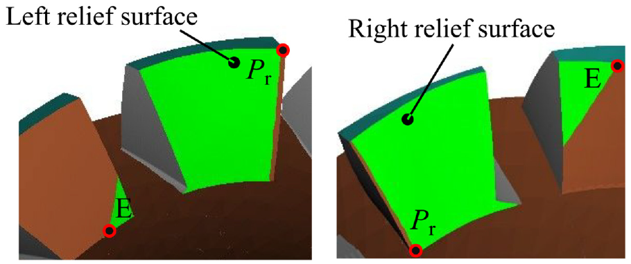
The variation trend of grinding boundary line and interference angle will be analyzed by taking one helix of the hob. For this example, the influence of relief grinding on the left and right sides of the cutting teeth T1, T2, T3, and T4 are studied, as shown in Figure 11.

Views in S1 and S2 directions on one helix of the hob.
The measuring points relationship between the grinding boundary line and the land edge when grinding the left relief surface Ai are shown in Figure 12. The interference angles θiL changing law along torus radius are shown in Figure 13. It can be seen that the interference angle changing trend of each cutting tooth is smaller from tooth root to top. And the minimum interference angle θiL is located at the tooth root of the cutting tooth T1, which is the most likely position to cause grinding interference when grinding the left relief surfaces.

Checking points for left relief surfaces.

Interference angle for left relief surfaces.
Using the same method to analysis the right relief surface Bi. The measuring points relationship between the grinding boundary line and the land edge when grinding the right relief surface are shown in Figure 14. The interference angles θiR changing law along torus radius are shown in Figure 15. It can be seen that the interference angle changing trend of each cutting tooth is larger from tooth root to top. And the minimum interference angle θiR is located at the tooth top of the cutting tooth T4, which is the most likely position to cause grinding interference when grinding the right relief surfaces.
Checking points for right relief surfaces.

Interference angle for right relief surfaces.
Therefore, there are two grinding interference positions that need to be checked of a toroidal worm wheel hob,
Point E on the left relief surface at root position of the cutting tooth T1. This point E is obtained when grinding the point Pr on the land edge at the tooth top of the cutting tooth T1, as shown in Figure 16.
Point E on the right relief surface at top position of the cutting tooth Tn−1, and n = 5 of the given example. This point E is obtained when grinding the point Pr on the land edge at the cutting tooth root of Tn−1,as shown in Figure 17.

Maximum checking position of left relief surface.
Maximum checking position of right relief surface.
Based on the above analysis, two minimum interference angles θi at two positions need to be checked. These two positions are the maximum interference points when grinding the left and right relief surfaces. As long as the maximum interference points do not interfere with the next cutter tooth, it can ensure that the whole toroidal worm wheel hob will not interfere when grinding the relief surfaces.
Analysis of the maximum number of cutting teeth avoiding grinding interference
Based on the example in Table 1, the value of the maximum number of cutting teeth to avoid grinding interference will be studied. The phase angle between the throat rake face and the left and right tooth rake faces is φz = 144.0°. If the number of the cutting teeth on one helix are setting as n = {3, 5, 7}, the phase angle between two adjacent cutting teeth are φf = {144°, 72°, and 48°}. The grinding results of the relief surfaces for are n = {3, 7} are shown in Figure 18, and it can be seen that there is no grinding interference.

Grinding results of the relief surfaces with different n.
When the number of the cutting teeth on one helix is setting as n = 9 and φf = 36°, the relief grinding interference occurs, as shown in Figure 19. The cutting teeth of the two checking positions are damaged by the grinding wheel.
Relief grinding interference with n = 9.
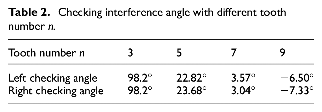
When taking different values of n = {3, 5, 7, 9}, the interference angles at the two check positions on the left and right relief surface are shown in Table 2. The changing trend between the checking interference angle of the two positions and the number of cutting teeth n of one helix are drawn into curves, as shown in Figure 20. As can be seen from Figure 20, the checking interference angle value gradually decreases with the increase of the number of cutting teeth. When the given number of cutting teeth is n = 9, the interference angles are less than zero, and that means that the phenomenon of the relief grinding interference occurs. Therefore, for the given parameters in this example, the maximum number of cutting teeth allowed to be arranged on one helix of the toroidal worm wheel hob is nmax = 7.
Checking interference angle with different tooth number n.

Relationship between checking interference angle and number of cutting teeth.
Relief grinding experiment by virtual four-axis CNC toroidal worm machine
The relief grinding simulation experiment is carried out in this section. The solid model of the toroidal worm wheel hob without relief grinding is build firstly. When the number of cutting teeth on a helix is n = 7, the toroidal worm wheel hob in the example has a total of seven rows cutting teeth, and the whole hob has 49 cutting teeth. Surfaces coordinates of the hob blank without relief grinding are calculated, and the 3D model of the hob blank is fitted in the software SOLIDWORKS, as shown in Figure 21.

The blank of the toroidal worm wheel hob without relief grinding.
The relief grinding simulation is carried out in VERICUT software. A four-axis CNC toroidal worm grinding machine contains four axes is built in VERICUT, as shown in Figure 22. Add the linear moving X-axis firstly, and then add the linear moving Z-axis on the X-axis. The rotating B-axis is added on the Z-axis. The spindle is mounted on the B-axis, and the grinding wheel is mounted on the spindle. C-axis is the workpiece mounting axis on which the hob blank is mounted. The grinding wheel is built in the tools magazine. The relief grinding programs are put into the virtual grinding machine to realize the relief grinding.

Virtual four-axis CNC toroidal worm machine for relief grinding.
Putting the fitted 3D model into the machining simulation software VERICUT as the blank before relief grinding. And then the relief surfaces grinding simulation are carried out in VERICUT with the calculated grinding movements (φB, φC, Δa, Δc). The results after machining simulation are shown in Figure 23, and there is no grinding interference.
Toroidal worm wheel hob after relief grinding.
Conclusion
In order to realize the continuous precision machining of the toroidal worm wheel hob with high density cutting teeth, this paper studies the relief grinding interference between the grinding wheel and the adjacent cutting teeth, and the conclusions are as follows.
The interference angle was defined to indicate the relief grinding interference. The angle between the grinding boundary line projection and the cutting edge projection is the grinding interference angle. The interference angle can be calculated by the coordinates (x, y), and the coordinates z is not need, which can simplify the calculating process.
By analyzing the variation law of the interference angle during relief grinding, it is determined that the maximum interference positions are two places. By calculating the interference angle of the maximum interference position, it can be judged whether the grinding interference of the relief surface will occur in the whole grinding process of the toroidal worm wheel hob.
The maximum tooth density design is studied under the condition of given grinding wheel parameters and toroidal worm wheel hob parameters to avoid the relief grinding interference. The design of the maximum number of the cutting teeth of the toroidal worm wheel hob can improve the worm wheel surfaces’ quality and reduce the running-in time of the toroidal worm pair.
Footnotes
Handling Editor: Chenhui Liang
Declaration of conflicting interests
The author(s) declared no potential conflicts of interest with respect to the research, authorship, and/or publication of this article.
Funding
The author(s) disclosed receipt of the following financial support for the research, authorship, and/or publication of this article: This work was supported by the State Key Laboratory of Mechanical Transmissions Open Fund (Grant No. SKLMT-MSKFKT-202117).