
Abstract
The ultra-precision master gear with high pitch accuracy has important applications in the calibration of high-precision gear measuring instruments or coordinate measuring machines and in military industries. In order to improve pitch deviations of ultra-precision gear, two gear-grinding techniques to improve pitch deviations of ultra-precision gear were proposed. First, based on the indexing plate system, the working principle of indexing plate and error transferring rules were discussed, and the technical approaches of decreasing the geometric eccentricity were proposed. Then according to the error interference principle, the offset-compensated technique and the neighbour-tooth translocation technique were proposed to improve the pitch machining accuracy of ultra-precision master gear. Finally, precision gear-grinding experiments were conducted by adopting the neighbour-tooth translocation technique based on offset-compensated technique. And the single pitch deviation fp of the test specimen is reduced from 1.06 to 0.63μm and the total cumulative pitch deviation Fp is reduced from 3.11 to 1.98μm with measurement uncertainty U95 = 0.33μm, which both reach the highest class (class 1 defining in ISO 1328-1:2013). The results show the efficiency and practicability of the two gear-grinding techniques to machine ultra-precision master gear.
Keywords
Introduction
Gears are one of the most important basic components in modern industries and are widely used in the field of equipment manufacturing, automobile, ship engineering, aerospace, precision instrument and military industry. With the development of industrial modernization, the requirements of gear machining accuracy are exponentially increasing.
Gear pitch accuracy is one of the most important accuracy indexes, of which the single pitch deviation (SPD) fp and the total cumulative pitch deviation (TPD) Fp are two of the default inspection items defined in gear international standard ISO 1328-1: 2013. 1 The accuracy requirement of the ultra-precision master gears (UMGs) that are used to calibrate high-precision gear measuring instruments (GMI) or coordinate measuring machines (CMM) for measuring gear is much higher. Due to the lower machining accuracy of gear pitch and effects of gear profile deviations and tooth surface roughness on the measuring uncertainty, the gear-like artefacts are used to calibrate the measuring uncertainty of GMI or CMM. The Italian scholar Maria Pia Sammartini designed and manufactured the gauge block gear-like artefact (GBA; as shown in Figure 1(a)). 2 However, the mounting accuracy of the GBA is much lower (fp = 19μm and Fp = 45μm). Therefore, the GBA is not suitable for calibrating high-precision GMI or CMM. The Japanese scholar Yohan Kondo has developed a multi-ball artefact (MBA; as shown in Figure 1(b)) to calibrate the measuring uncertainty of the instruments.3–5 Due to the higher machining accuracy (the sphericity is not more than 100 nm) and lower roughness of the ball, the effect of the MBA on the measuring uncertainty of GMI or CMM is much lower. SPD fp of the MBA can reach about 2 μm and the TPD Fp can reach about 4μm. Such MBA can be taken as a master gear with class 2 accuracy and can meet the calibrating requirement of the high-precision GMI or CMM.
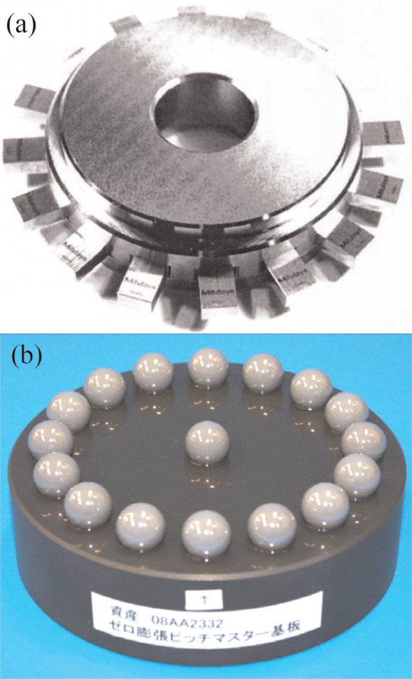
Gear-like artefacts: (a) the GBA gear-like artefact and (b) the MBA gear-like artefact.
Since the UMG has high pitch accuracy, high profile accuracy and high helix accuracy simultaneously, it can be used to calibrate several indexes of the GMI or CMM. In order to develop the UMG with higher pitch accuracy, pitch machining techniques of UMG are discussed based on the analysis of the working principles and error transferring rules of the indexing system.
Principles and rules
At present, there are mainly two kinds of indexing systems of the high-precision gear grinder; they are the mechanical indexing system and the computerized numerical control indexing system. According to the different indexing components, the mechanical indexing system is classified into the wheel-worm indexing system, the indexing plate (IDP) system and the end-tooth indexing (ETI) system; among these, the indexing accuracy of ETI system is the highest, followed by the IDP system. Although the ETI system has the higher indexing accuracy, considered the complex machining processes and the higher machining costs, the ETI system is not widely used in the manufacturing field. In contrast, the IDP system has wide utilization in the field of machining UMG, gear shaper cutters, gear shaving cutters and so on. Taking the IDP system in gear grinder as an example, the effects on SPD fp and the TPD Fp of the gear to be ground are analysed.
Working principle of IDP in gear grinder Y7125
The indexing system of the gear grinder (such as Y7125 made in China) with flat-faced grinding wheel is the IDP system. In gear grinder Y7125, the generating system and the indexing system share one and the same generator. One way of the motion outputted from the generator passes by four-level tower shifting, crank and rocker mechanism, rocker and slider mechanism and cam-baffle mechanism to realize the generating motion of the gear grinder. The other way passes by four-level tower shifting, bevel gear pair, flexible axle, indexing worm and Geneva wheel mechanism to drive the indexing gears and indexing cam simultaneously, and to realize the intermittent motion of the IDP. The rough indexing is realized by choosing different indexing gears. Then the indexing cam rotates beyond the maximum peak, and the locating detent draws back under the function of spring force and clutches in the slot of the IDP, which realizes the precision indexing of the IDP. The indexing accuracy of the IDP is mainly determined by the machining accuracy of the slot and the mounting accuracy of the IDP.
The gear to be ground and the IDP are mounted to one and the same grinding mandrel. If there are no eccentricity errors between them, the IDP and the gear to be ground will have the consistent axis of rotation, and the pitch deviations of the gear are only from the manufacturing error em of the slots of the IDP in theory. However, the mounting error ei (the so-called kinematic eccentricity) between the IDP and the grinding mandrel and the mounting error eg (the so-called geometric eccentricity) between the gear to be ground and the grinding mandrel are inevitable, which are the main error sources of the gear pitch deviations. The working principle of the IDP is shown in Figure 2. In addition, the choice of the finishing occasion, the uniform of the feed quantity and feed occasion, the finishing circle length and the gear-grinding technique also affect the grinding accuracy of the gear pitch.
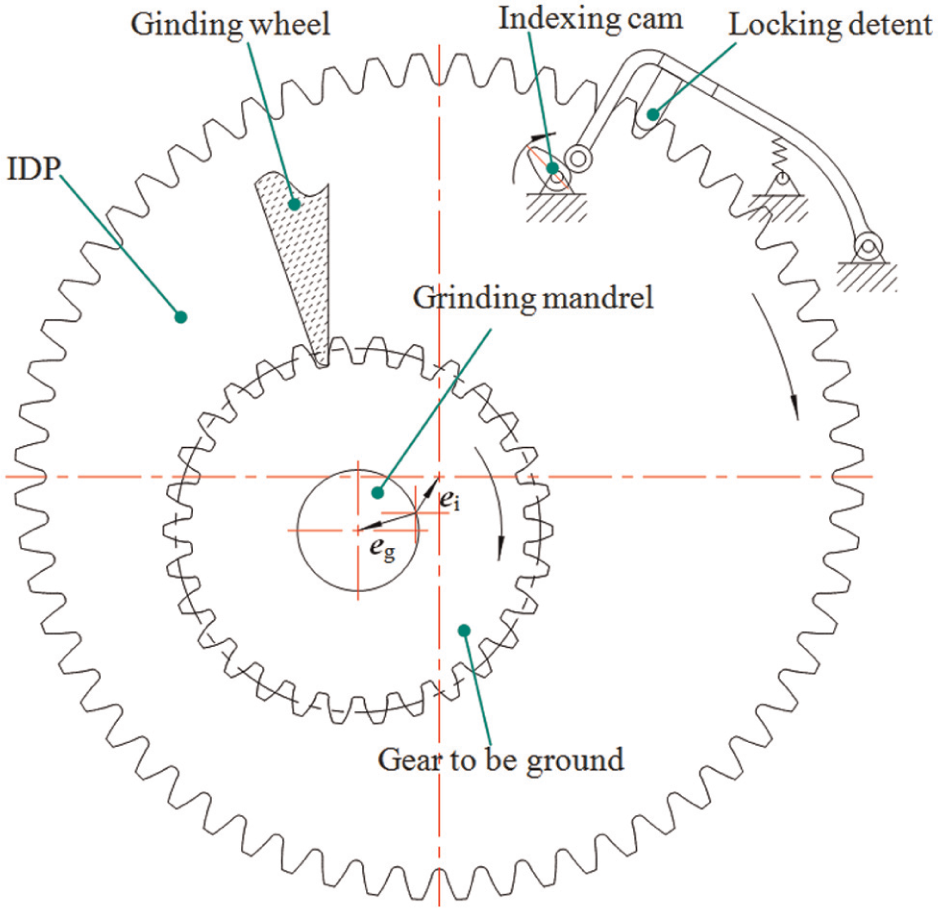
Working principle of the IDP.
Transferring rules of pitch deviation
The kinematic eccentricity ei and the manufacturing error em of the slots of the IDP can cause the indexing error of the indexing system. The total indexing error
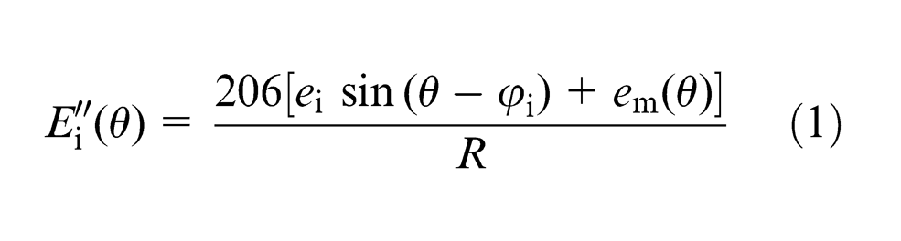
where R (mm) is the working radius of the IDP, θ (°) is the phase angle corresponding to the slot of the IDP and
Since the gear to be ground and the IDP are mounted to one and the same grinding mandrel, the total angle indexing error of the IDP will transfer to the gear to be ground by the same value if taking no consideration of Abbe error. Therefore, the TPD of the gear to be ground determined by the total indexing error Ei(θ) (μm) of the IDP can be expressed as
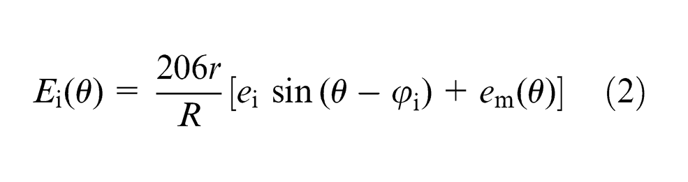
where r (mm) is the reference radius of the gear to be ground.
Since the working radius R of the slot of the IDP is definite value (as to gear grinder Y7125, R = 135 mm), the effect of the total angle indexing error of the IDP on the TPD of the gear to be ground takes on the tendency of direct proportion with the reference radius r. The comprehensive geometric error eg is mainly from the mounting error and the axial float of the gear-grinding mandrel, and the ending beats of the locking face of the gear blank. The TPD Eg(θ) (μm) of the gear to be ground determined by the comprehensive geometric error eg can be expressed as
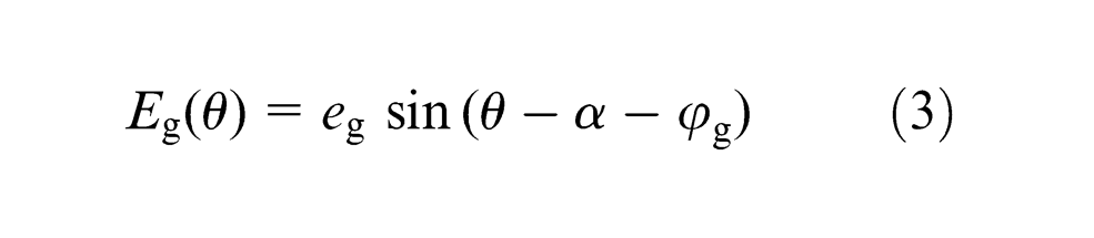
where α (°) is the pressure angle of the reference circle, θ (°) is the phase angle corresponding to the blank and
Therefore, the TPD Fp(θ) (μm) can be obtained by adding equation (2) to equation (3), that is
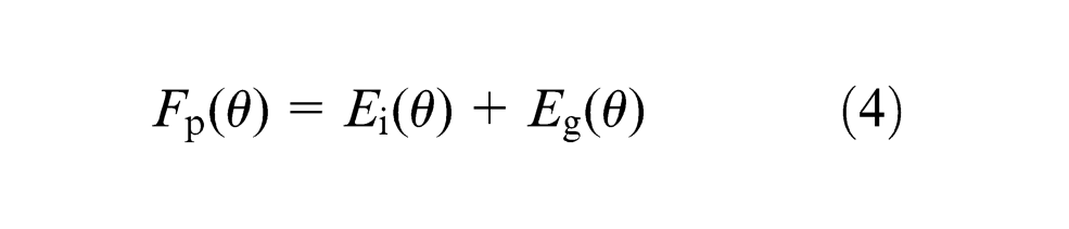
Because the trigonometric function of equations (2) and (3) is of the same frequency (360°), the overlapping result of individual TPD Fp(θ) also has the same frequency. Finally, the effects of the kinematic eccentricity ei, the comprehensive geometric error eg and the manufacturing error em of the slots on the individual TPD of the IDP on gear blank can be expressed as
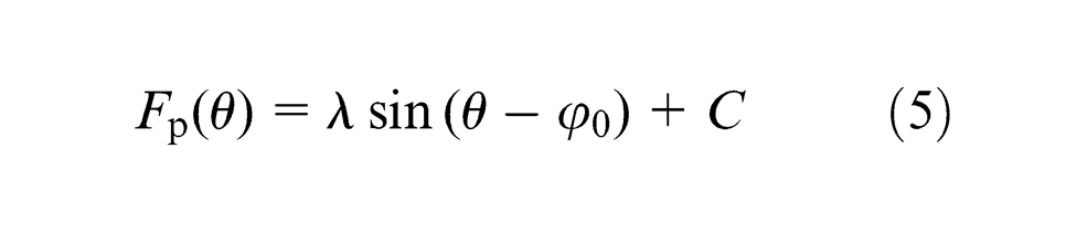
where λ (μm) is the amplitude of the composed vector,
Expressing the independent variable θ as the function of the number of teeth i, equation (5) can be rewritten as
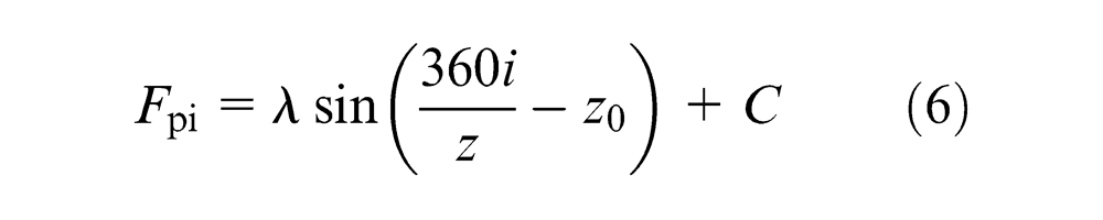
where z is the number of teeth, i is the integrity from 1 to z, z0 is the initial the number of teeth and Fpi is the individual TPD.
The TPD Fp is the largest algebraic difference between the individual cumulative pitch deviations, that is
The individual SPD fpi can be expressed as
The SPD fp is the maximum absolute value of all the individual SPD, that is
As can be seen from equation (6), the effects of the kinematic eccentricity ei and the comprehensive geometric error eg on the individual TPD take on the tendency of basic harmonic wave. The minimum value of λ can be obtained by choosing the right phase angle between ei and eg, which decreases the effects of the kinematic eccentricity ei and the comprehensive mounting error eg on the individual TPD Fpi. The kinematic eccentricity ei can only affect the pitch deviations of the gear to be ground; however, the comprehensive geometric error eg not only affects the gear pitch deviations but also affects the gear profile deviations. Therefore, during the machining of precision gear-grinding, a decrease in the comprehensive geometric error eg should be considered first, and then the adjusting radial quantity of the IDP to reduce ei according to the pitch curve of the gear to be ground.
Gear-grinding techniques
Approaches of decreasing the comprehensive geometric error eg
The sliding shaft system was refitted as the antifriction bearing system which includes two multi-ball axle sleeve (MAS). The rotation error of the gear-grinding principal shaft can be reduced from 2 μm to below 0.5μm by choosing the high-grade (above G5) stainless steel ball with 0–3μm magnitude of interference.
The radial adjustable gear-grinding mandrel (RGM) with four symmetrical adjusting screws was designed. The angle between the adjusting direction of the screws and the locating surface is 15°, as shown in Figure 3. The radial run out of the working section of the mandrel can be reduced to about 0.5μm by adjusting the four screws of the RGM. The ending beats of the locking face of the RGM to the rotation line can reach about 1μm. The mounting of the gear blank to the RGM adopts MAS with 0–3μm magnitude of interference.
In order to improve the mounting accuracy of the gear blank to RGM, the ending beats of the locking faces of the gear and the RGM were measured, and the optimal mounting position was chosen by error compensation method.
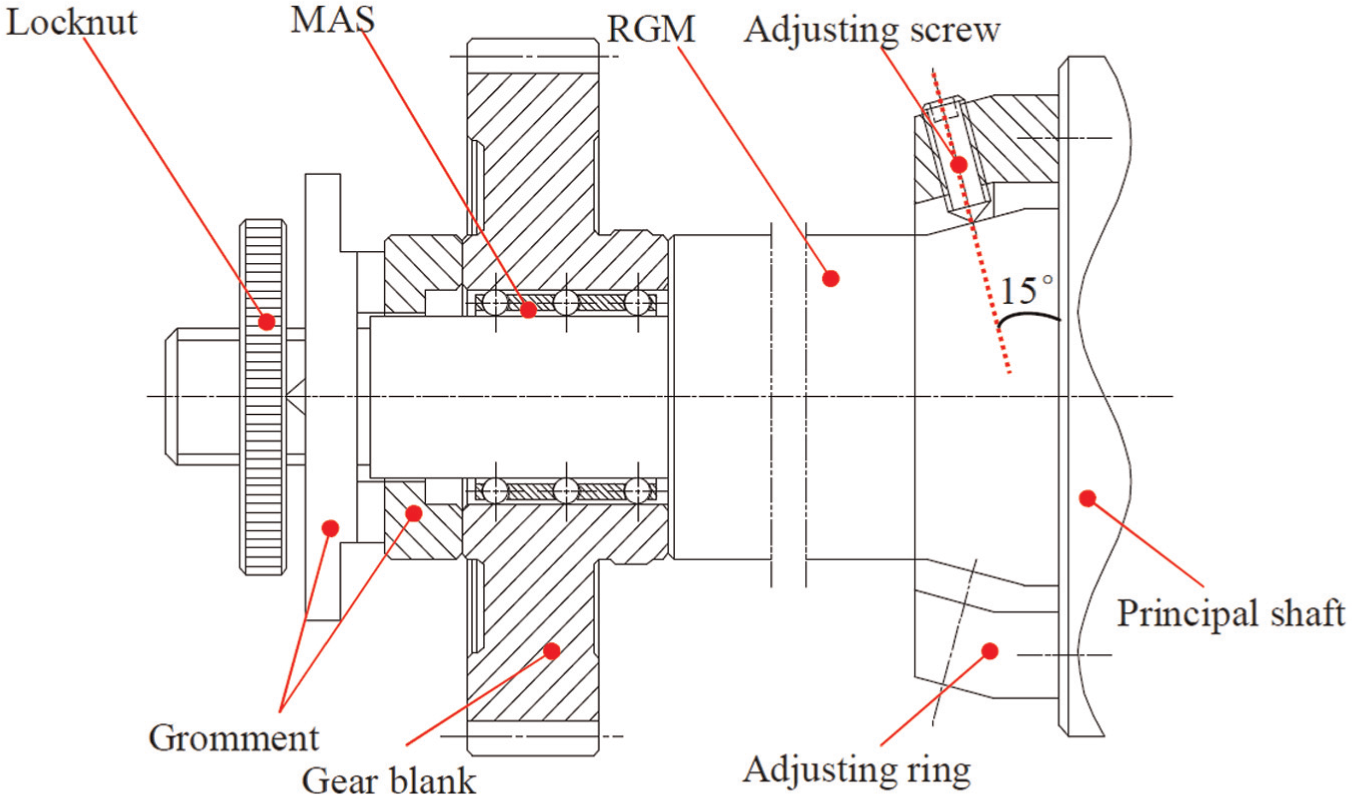
Radial adjustable gear-grinding mandrel (RGM).
The comprehensive geometric error eg can decrease to 0.5 μm by the adopting the approaches mentioned above. After that, the effects of eg on Fp are not more than 1 μm and that of eg on fp are still less.
Offset-compensated technique
The bigger harmonic component of Fpi of the gear to be ground is mainly from the kinematic eccentricity error ei of the indexing system, the comprehensive geometric error eg of the gear blank and the basic harmonic component of em. According to equation (5), we can consider the harmonic error of the Fpi of the gear to be ground is all caused by the kinematic eccentricity ei error of the indexing system. That is to say, the basic harmonic error of the Fpi can be completely compensated by offsetting the IDP. However, it is very difficult to determine the amplitude λ and the initial phase angle
First, a precision gear-grinding experiment is conducted to make the systematic error (ei, eg and em) reflect to the gear to be ground as far as possible. Then the amplitude λ and the initial phase angle
First, the structure of the IDP is reformed, which includes finishing a radial datum cylindrical surface, enlarging the size of the radial locating cylindrical surface about 1 mm and adding four adjusting screw holes in radial direction. The radial adjustable IDP is shown in Figure 4.
Since the machining datum of the radial datum and the IDP’s slots are the same, the radial datum can be used as the initial datum of the radial adjusting of the IDP. A precision gear-grinding experiment is conducted to copy the kinematic eccentricity error to the TPD of the gear to be ground as far as possible.
The error curve of Fpi is drawn and the magnitude and the phase angle of the basic harmonic component are fitted by the least square method, and the radial adjusting quantity Δ and adjusting direction (90° lagging to Fpi) are determined according to equation (2).
After adjusting the IDP according to the theoretical value Δ and theoretical adjusting direction, another precision gear-grinding experiment is conducted. Due to the adjusting error, it is hard to completely eliminate the basic harmonic component by one-time adjusting operation. Repeating Step 3, the basic harmonic component of the error curve of Fpi can be thoroughly eliminated in theory. Then the radial position of the IDP that corresponds to the smaller TPD Fp is recorded and taken as the mounting datum of the IDP.

Radial adjustable IDP.
The basic harmonic component of the error curve of Fp can be reduced by adopting OCT that is considered as one of the most effective methods to improve the machining accuracy of the gear TPD. However, the effects of the OCT on improvement of the machining accuracy of the gear single pitch are not obvious.
Neighbour-tooth translocation technique
The gear SPD fp is one of the most difficult accuracy items to ensue. The error sources of the gear single pitch are mainly from the manufacturing error of the indexing element (e.g. the IDP) and the random error in machining the gear. Although the manufacturing error of the indexing element is the systematic error of the gear to be ground, the machining error of the indexing element shows some random characteristics, which results that the error curve of fpi also shows some random characteristics. If the error curve is shifted forward or backward at an angle of one tooth, two error curves of fpi will interfere with each other, which results that some tooth surfaces that have relative machining allowances are reground. According to the error interference principle, some tooth surfaces that have relative machining allowances are reground to achieve the effects of decreasing the gear SPD by controlling the feed quantity or the number of teeth of the gear teeth that participate in regrinding; this is the basic idea of neighbour-tooth translocation technique (NTT). Since the feeding accuracy directly affects the machining accuracy by adopting NTT, the number of teeth that participates in regrinding processes being slightly more than half the total number should be strictly controlled.
According to the closure measuring technique,6–8 the algebraic sum of the individual SPD fpi should be 0, that is

Equation (8) shows that the mean of the set of fpi, which has random characteristic, is expected to be 0. In order to facilitate research, a set of random number of fpi between ±fp is supposed as
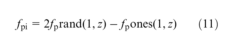
where rand(1, z) expresses a row vector of z random numbers between 0 and 1 and ones(1, z) expresses az-dimensional row vector and all the components are 1.
According to the differences of the translocation directions and the translocation times, the neighbour-tooth translocation can be realized by one-tooth translocation that contains one-tooth left translocation (curve a1) and one-tooth right translocation (curve b1), and two-tooth translocation that contains one-tooth left first then two-tooth right (curve a2) translocation and one-tooth right then two-tooth left translocation (curve b2).
Taking fp = 2μm and the number of teeth z = 30 for example, a set of random error curve (defined as the initial error curve f0) is created by software MATLAB. And the simulation results of different type neighbour-tooth translocation are shown in Figure 5.
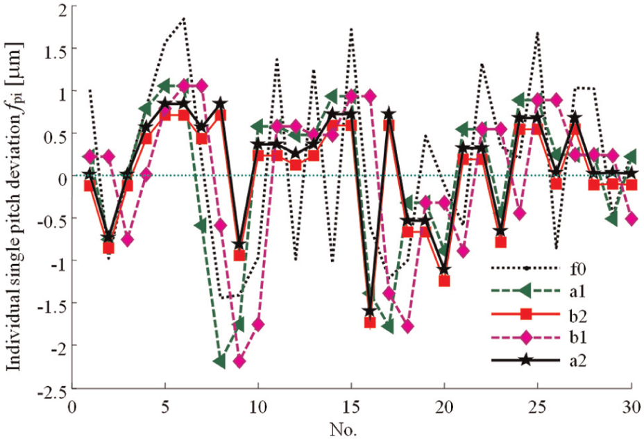
Simulating results of NTT.
The following conclusions can be drawn from Figure 5:
Error curves a1 and b1 obtained by adopting one-tooth NTT have the same amplitude. However, the phases of them differ at an angle of a tooth. Error curves a2 and b2 obtained by adopting two-tooth NTT have no obvious differences both at the amplitudes and the phases.
The overall effects by adopting two-tooth NTT are superior to that by adopting one-tooth NTT translocation.
No matter which kind of NTT is used, the effects of some teeth whose deviations show the high–low alternation in the initial error curve f0 (such as the number of teeth 11–15) on the gear individual SPD fpi are remarkable. However, the effects of some teeth whose deviations show continuous variation in the initial error curve f0 (such as the number of teeth 2, 9, 16 and 20) on the gear individual SPD fpi are not remarkable. Therefore, the improved effect of NTT on the gear individual SPD fpi depends on the proportion of teeth whose deviations show the high–low alternation.
Gear-grinding experiments
The gear grinder with flat-faced grinding wheel Y7125 (made in China) is taken as the grinding equipment, as shown in Figure 6. The rotation error of the RGM can reach 0.5 μm by adopting the approaches mentioned in section ‘Approaches of decreasing the comprehensive geometric error eg’; the indexing accuracy of the indexing system is
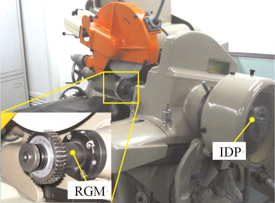
Gear-grinding equipment with flat-faced grinding wheel (Y7125).
Gear-grinding experiment by adopting OCT
First, the approaches of decreasing the comprehensive geometric error eg mentioned in section ‘Approaches of decreasing the comprehensive geometric error eg’ are adopted to improve the mounting accuracy of the gear blank. Then the gear-grinding technique of OCT using the high-precision IDP, which is finished by an ETI device, is adopted. Finally, the precision measurements of the individual TPD Fpi and SPD fpi are obtained using the multi-step method in an ETI table with measurement uncertainty U95 = 0.33μm. 11 The measurement device is shown in Figure 7, and the pitch measurement results of the specimen are shown in Figure 8.
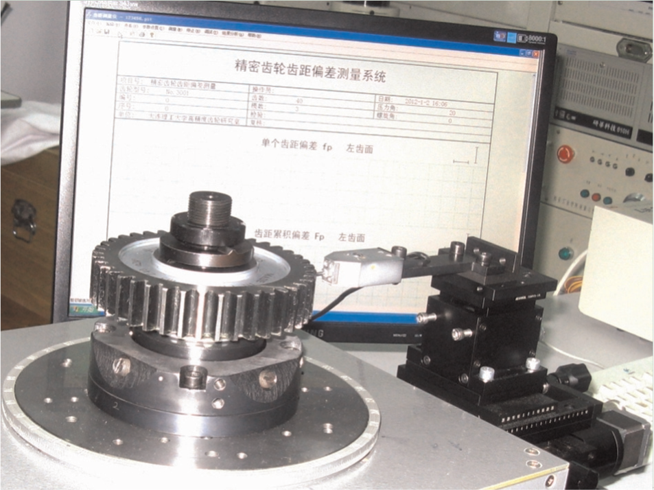
Measurement device of gear pitch deviation.
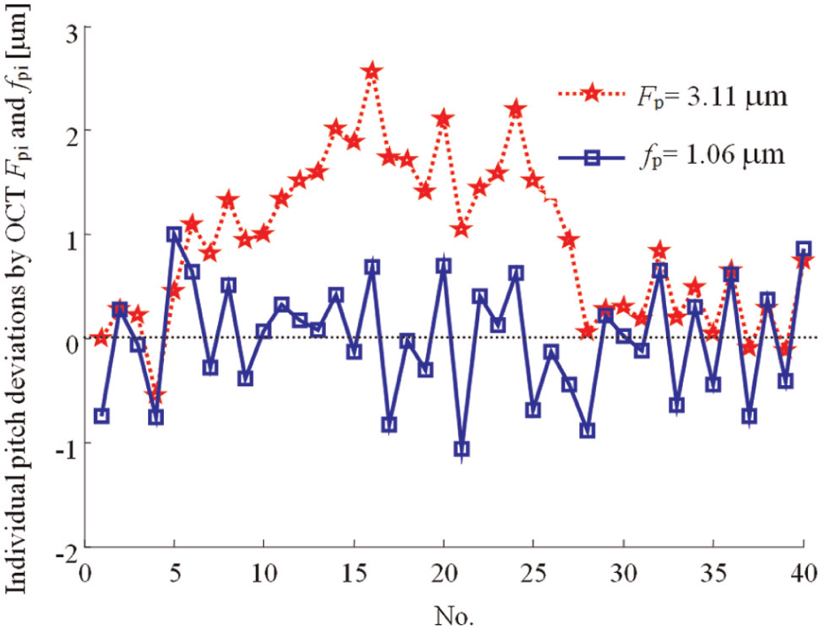
Initial pitch error curve by OCT.
As can be seen from Figure 8, after adopting the high-precision IDP and the gear-grinding technique of OCT, the TPD Fp is reduced to 3.11 μm and SPD fp is reduced to 1.06μm. The basic harmonic component of the error curve of Fpi can be further decreased by adopting OCT. However, the effects of the OCT on improvement of the machining accuracy of gear SPD fp are not obvious. In the next, the gear-grinding excrement by adopting the NTT is conducted to further reduce SPD.
Operating processes of NTT
The operating processes of NTT are shown in Figure 9. First, the fine machining of the gear flank is finished with no translocation (the relative position between the IDP and the gear blank is shown as P0 in Figure 9(a)), and the result of the fp is obtained by the precision measurement in precision pitch measurement device, as shown in Figure 8. Then according to the accuracy requirement of the gear blank, the one-tooth NTT or the two-tooth NTT is chosen. If the one-tooth NTT is chosen, we take the gear blank rotate to left (the relative position between the IDP and the gear blank is shown as P1 in Figure 9(b)) or right relative to the IDP at angle of one tooth. If the two-tooth NTT is chosen, based on the one-tooth NTT, we continue to conduct the two-tooth NTT at angle of two tooth in negative direction (the relative position between the IDP and the gear blank is shown as P2 in Figure 9(c)). The tooth number of the gear that participates in regrinding processes being slightly more than half the total number of gear is strictly controlled in each process. The comparison of the translocation results by adopting the one-tooth NTT and the two-tooth NTT is shown in Figure 10.
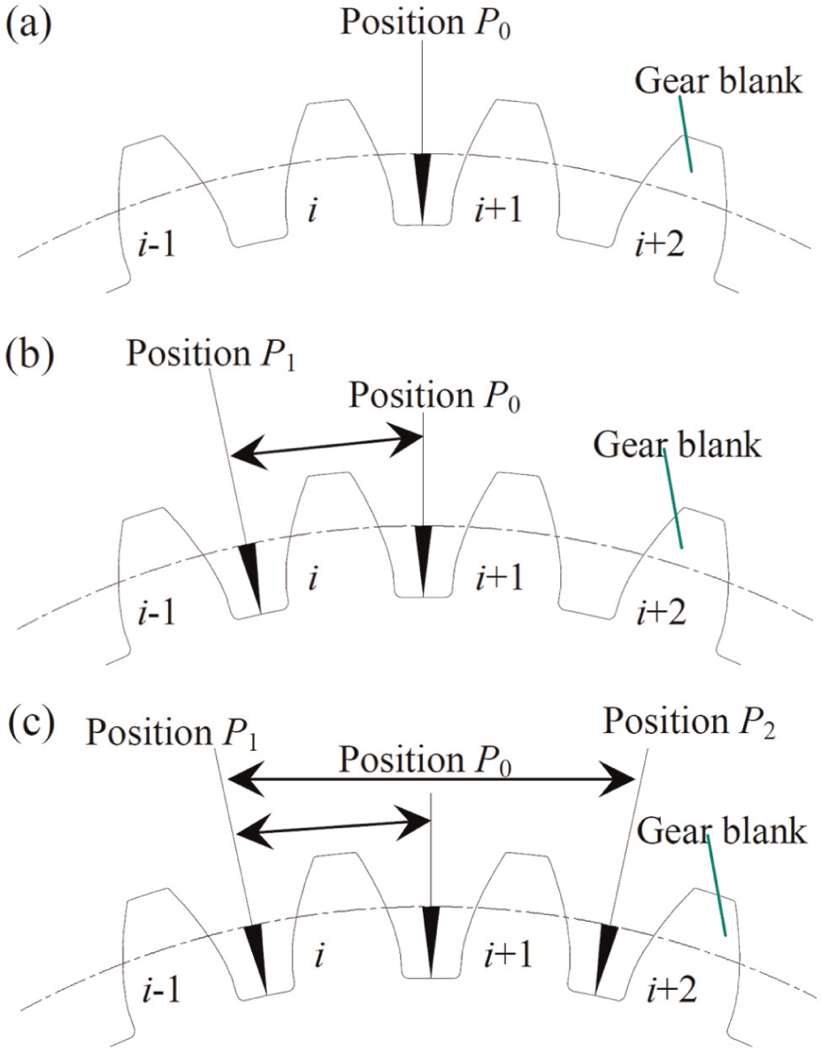
Operating processes of NTT: (a) the relative position between the IDP and the gear blank as no translocation (P0), (b) the relative position between the IDP and the gear blank as one-tooth translocation (P1) and (c) the relative position between the IDP and the gear blank as two-tooth translocation (P2).
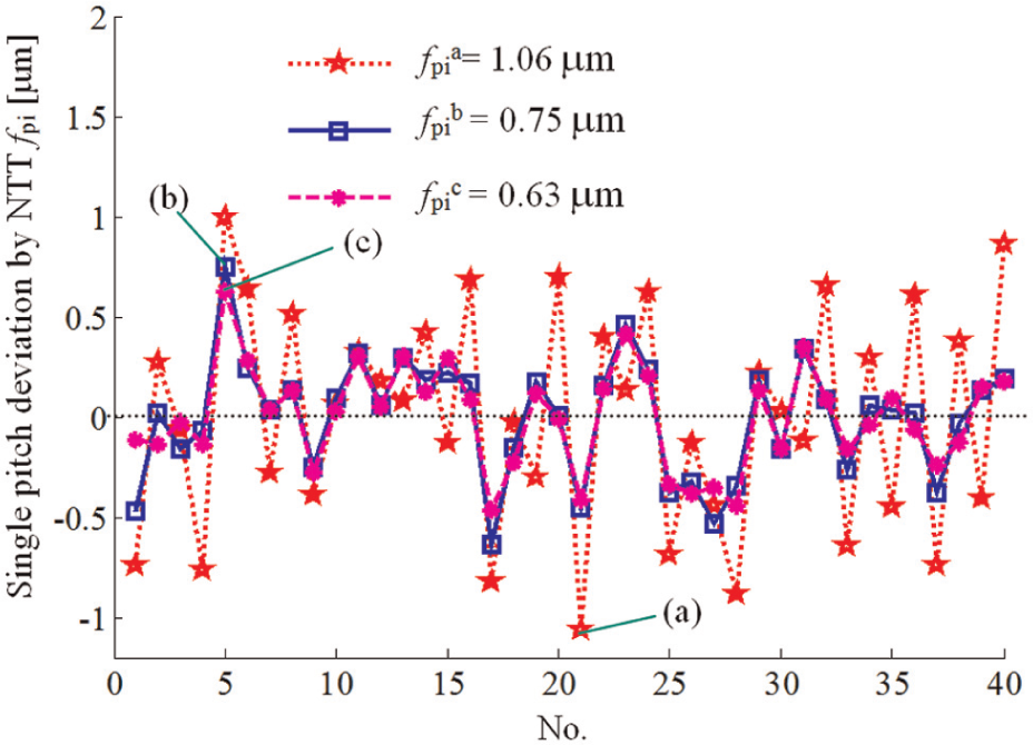
Effects on SPD by adopting NTT: (a) the initial error curve of fpi, (b) the error curve of fpi by adopting one-tooth NTT and (c) the error curve of fpi by two-tooth NTT.
As can be can be seen from Figure 10, the SPD fp of the specimen is reduced from 1.06 to 0.75μm by adopting one-tooth NTT, and the relative error is reduced by 29.2%; the SPD fp of the specimen is reduced from 1.06 to 0.63μm by adopting two-tooth NTT, and the relative error is reduced by 40.6%. The experimental results show that the effect of machining accuracy of single pitch is significant by adopting the NTT, especially the two-tooth NTT. However, the machining mechanism of the NTT and quantitative analysis of the effects still need further study in the future.
In theory, adopting the NTT will not change the variation trend of the error curve of the individual TPD Fpi. However, the pitch deviation of the gear teeth that have the relative machining allowance is further reduced by adopting the NTT. Therefore, the TPD Fp will be reduced slightly. The variation trend of the error curve of the individual TPD Fpi is shown in Figure 11 by adopting the NTT.
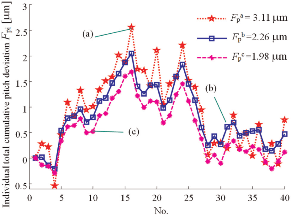
Effects on TPD by adopting NTT: (a) the initial error curve of Fpi, (b) the error curve of Fpi by adopting the one-tooth NTT and (c) the error curve of Fpi by adopting the two-tooth NTT.
As can be can be seen from Figure 11, the TPD Fp of the specimen is reduced from 3.11 to 2.26 μm by adopting one-tooth NTT, and the relative error is reduced by 27.3%; the TPD Fp of the specimen is reduced from 3.11 to 1.98μm by adopting two-tooth NTT, and the relative error is reduced by 36.3%. The experimental results show that not Fp but the fp is reduced by adopting NTT, of which the effects of the former are more significant than that of the latter.
Conclusion
It can be concluded that based on the analysis of the principle and the error transferring rules of the IDP system, two kinds of gear-grinding techniques to improve the machining accuracy of fp and Fp are proposed, they are the OCT and the NTT. Initially, the article proposed some approaches of decreasing the comprehensive geometric error eg, which conclude adopting the MAS and designing the RGM.
Then according to the error interference principle, the article proposed the basic idea of OCT, that is, the gear pitch deviation is compensated by radial setting off the IDP according to the magnitude and the phase angle of the basic harmonic component of Fpi. And the detailed operations of OCT were stated.
In addition, another gear-grinding technique NTT was proposed. According to the characteristics of fpi, taking the error curve of fpi shifted forward or backward at an angle of one tooth, two error curves of fpi will interfere with each other, which results that some tooth surfaces that have relative machining allowances are reground.
Finally, precision gear-grinding experiments were conducted by adopting approaches of decreasing the comprehensive geometric error eg and OCT. The experimental results show that the machining accuracy of gear pitch deviations can reach the highest class. Based on the OCT, another precision gear-grinding experiment was continued by adopting NTT; the machining accuracies of fp and Fp are further upgraded. Finally, SPD fp of the test specimen reaches 0.73μm and the TPD Fp of the test specimen reaches 1.98μm with measurement uncertainty U95 = 0.33μm. The experimental results show the efficiency and practicability of the OCT and the NTT to machine UMGs.
Footnotes
Declaration of conflicting interests
The authors declare that there is no conflict of interest.
Funding
This study was supported by the National Natural Science Foundation of China (51305059) for their support and also China Postdoctoral Science Foundation Funded Project (2013T60279) and the Fundamental Research Funds for the Central Universities (DUT14QY17).