
Abstract
Waviness error is one of the most critical errors in the large aspheric lenses grinding and one that has a strong impact on the performance of the optical system. In this article, the waviness error of large axisymmetric aspheric lenses for X-axis direction as well as Z-axis direction is analyzed by employing grate parallel grinding method. The grinding wheel vibration and Z-axis interpolation pace are regarded as the main causes of the surface waviness error. Furthermore, to reduce the waviness error, the influence of grinding parameters on waviness error is investigated. The waviness errors measured during grinding experiments are in good agreement with the theoretical results and the appropriate grinding parameters are recommended.
Keywords
Introduction
The superior optical characteristics of aspheric lenses can be attributed to several merits, including less loss of laser energy and number of optical components, better image and high optical system performance. To obtain high quality, precision grinding is an appropriate method for large aspheric manufacturing.1–3 In general, the geometric errors are divided into three types: surface error, waviness error and roughness error. It can also be described as low-spatial frequency error, mid-spatial frequency error and high-spatial frequency error, respectively. In the traditional optical evaluation system, surface error and roughness error are usually used as indicators to evaluate the surface quality, and the waviness error is ignored. However, the waviness error can affect the sharpness of the point spread function, and control of these frequency components is essential to ensure the performance of the optical systems.4–6
Although grinding is not the final process for optical components’ manufacturing, the waviness errors caused by grinding process have to be eliminated thoroughly in polishing process. Even if the waviness errors are totally eliminated, it will be a time-consuming process. To reduce waviness error, the generation mechanism of waviness error should be discussed first. Generally, the wheel vibration is known as a main factor that causes waviness error. The wheel system that causes periodic forced vibration is a key part of vibration source in grinding process. The reasons for wheel forced vibration could be unbalanced wheel, eccentric mass, elastic deformations and so on. The vibration of wheel not only causes the chatter marks on the workpiece but also causes surface/subsurface damage due to the collision between wheel and workpiece. The origin of chatter that is particularly due to regenerative effects during surface grinding was explained by Inasaki et al. The active or passive damping methods were employed to suppressed chatter and information on a suitable procedure to conduct a stability assessment for grinding machines was provided. 7 Li et al. established a classical single degree of freedom model for chatter of contour grinding optical surfaces, according to both work and tool regenerative effects. Numerical simulations and grinding experiments were carried out and agreed well. 8 A mathematical model describing how vibration led to the error of workpiece surface profile was established by Zhang and Guo. The vibration amplitude, frequency and machining speed that affect the surface quality were discovered to decrease surface waviness error. 9 Pearce and Stone 10 described a model of centerless grinding that including the machine dynamics and regeneration on both the workpiece and the grinding wheel allows unstable vibration to be investigated. Bi et al. 11 investigated the effects of grinding wheel vibration on surface topography and decreased the waviness error of optical surface by choosing parameters. Jeffrey et al. 12 studied the effect of grinding wheel eccentricity on grinding forces, wheel wear and final waviness height. A model was developed to predict final scallop-profile shape from parameters and eccentricity. A new analysis and simulation model for surface topography of the grinding process is established by Cao et al. 13 The influence of grinding wheel vibration amplitude, wheel grit number, as well as grinding parameters on the surface waviness and roughness is discussed. Yao et al. analyzed the stability and bifurcation of the chatter vibration and found out that the dynamic of process was governed by quasi-static interactions. It was also shown that the wheel and workpiece chatters were quite different, having continuous and intermittent characters, respectively. 14
Although some academic research of grinding waviness errors were done, they mainly focus on regenerative effects of chatter or mathematical vibration model of surface grinding. As for large aspheric lenses grinding, the waviness errors of it have hardly been discussed. Moreover, the mechanisms of waviness errors are totally different when condition or principle of grinding changes. Therefore, this article focuses on the mechanism of waviness error of large axisymmetric aspheric lenses by employing grate parallel grinding method and aims at reducing waviness error effectively. The grinding parameters that affect the waviness error are analyzed and the relationship between waviness error and grinding parameters are discussed. Finally, the experiments were carried out to verify the theoretical results and the appropriate parameters are proposed.
Machining of large axisymmetric aspheric lenses
Grinding is an effective method for axisymmetric aspheric surface manufacturing. Some grinding methods, such as transverse grinding, parallel grinding, single-point inclined axis grinding and cup-wheel grinding, have been developed.15–17 Among these methods, the parallel grinding is generally applied in large axisymmetric aspheric lenses grinding due to advantage of low surface roughness, high surface accuracy and even wear. Therefore, a machining method called grate parallel grinding is proposed. The schematic diagram of grinding is illustrated in Figure 1. The merits of this method are that the grinding point is changed along the wheel profile and the wheel wear decreased remarkably to obtain better form accuracy of the ground aspherical profile. Furthermore, using three-axis grinding machine, compared to tradition grinding, the accuracy can be higher. 18
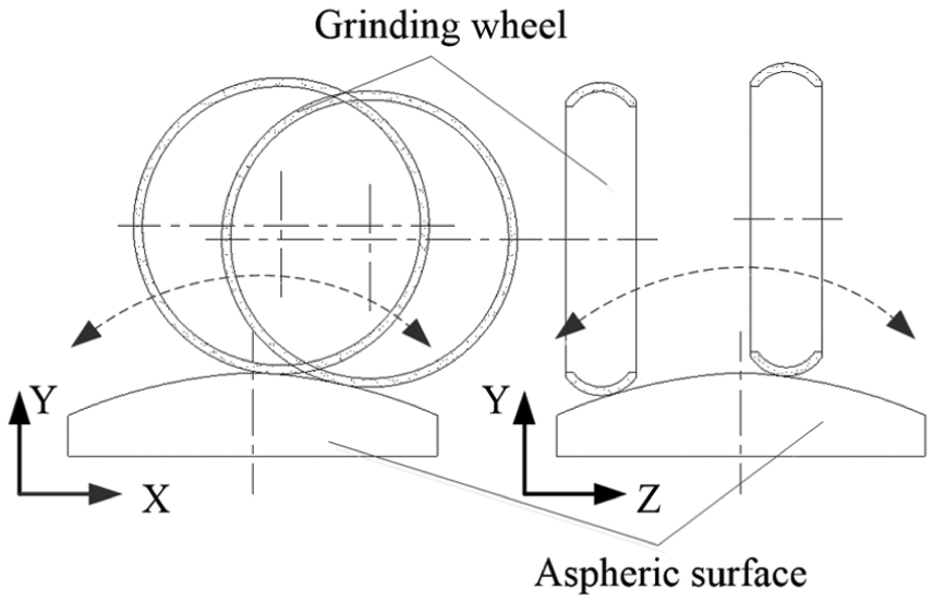
Schematic diagram of aspheric grinding.
Analysis of waviness error
Characteristic of X-axis waviness error
As we know, the wheel vibration is considered as a main critical factor of X-axis waviness error. Due to aspheric grinding principle and wheel center forced vibration caused by unbalanced weight in Y-axis direction, the wheel center vibration trace equation can be described as follows
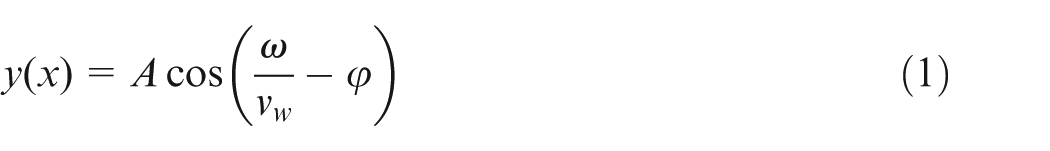
where ω is the wheel rotational frequency, vw is the X-axis feed rate, φ is the phase angle and A is the amplitude of wheel vibration.
Workpiece surface topography is generated by the kinematic interaction between grinding wheel and workpiece. The envelope curve, generated by kinematic interaction, would be the same as the wheel center curve without interference, which is a cosine curve with the period of 2πvw/ω. However, the interference between arc wheel and workpiece is inevitable and the envelope curve is no longer the same as the wheel center curve. As shown in Figure 2, the amplitude of envelope curve is 2A′, which is less than the amplitude of wheel center curve 2A by reason of grinding interference, but the period of them is still the same.
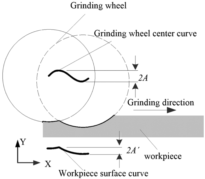
Interference between grinding wheel and workpiece.
The peak error value of workpiece surface is reduced by grinding interference, as shown in Figure 3. The point P(0, yp) is the position when the arc wheel reaches the peak of its center curve. Because of grinding interference, the position of point P(0, yp) changes to Q(0, yl). To analyze conveniently, the phase angle is ignored and the positions of wheel center curve are described as (x0, y0). The point Q is the intersection of arc wheel envelope curve and Y-axis. yl can be calculated and expressed as
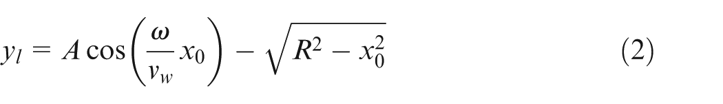
where R is the radius of the wheel.
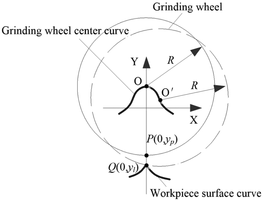
Forming principle of ΔA caused by interference.
The reduction of error peak ΔA is
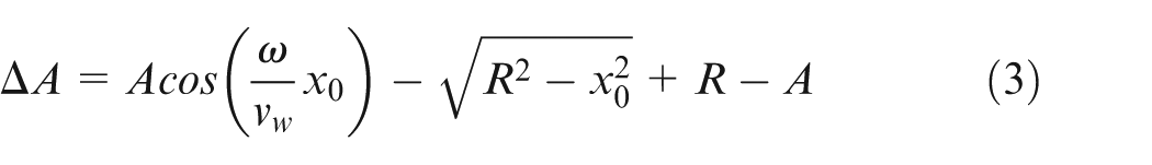
where
If ΔA > 0, grinding interference takes place in position x0. If ΔA < 0, there is no interference and the final peak position of envelope curve is formed when ΔA = 0.
The value of ΔA is related to many grinding parameters. Take the wheel radius, for example, Figure 4 testifies that the value of ΔA varies with the position of the grinding point and wheel radius. ΔA is less than zero with wheel radius R = 50 mm, while ΔA has two maximum values in a period with wheel radius R = 200 mm.
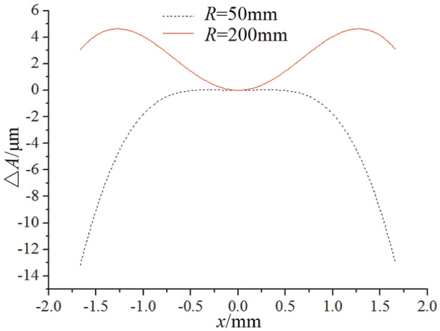
ΔA–x relation depending on wheel radius.
Effect of grinding parameters on X-axis waviness error
The grinding parameters, such as wheel radius, amplitude of wheel vibration, wheel speed and X-axis feed rate, have great impact on X-axis waviness error. If the wheel radius tends to zero, there is no grinding interference between wheel and workpiece. In that extreme case, the envelope curve is the same as grinding wheel curve, which can be expressed as A′ = A. When the wheel radius tends to infinity, the effect of interference is the most obvious and the envelope curve becomes a straight line, which can be expressed as A′ = 0. Between these two extreme cases, a threshold value can be found when the grinding wheel has just interfered with workpiece. The reduction of amplitude caused by grinding interference is defined as ΔA, which is used for evaluation. The more the value of ΔA, the less the value of waviness error. Figure 5 shows the relationship between ΔA and R.
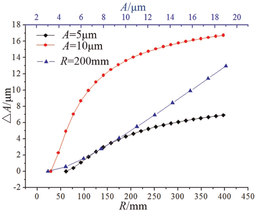
Relationship between ΔA, R and A.
As shown in Figure 5, the threshold value of wheel radius is 61 and 29 mm when A equals to 10 and 5 µm in the condition of vw = 5000 mm/min and n = 1500 r/min, respectively. When R < 61 mm or R < 29 mm for each condition, there is no grinding interference. In addition, the value of ΔA increases with the increase in wheel radius, but the growth rate is reduced gradually. As the value of wheel radius increased, the value of ΔA tends to 2A. On the other hand, ΔA also increases with the increase in A, and the threshold value of A is 3 µm in the condition of n = 1500 r/min, vw = 5000 mm/min and R = 200 mm.
The wheel speed n and X-axis feed rate vw are the factors that affect period of envelope curve. In theory, the more value of wheel speed or the less value of X-axis feed rate causes the less period of envelope curve that reinforces grinding interference and reduces the waviness error. Figure 6 shows the relationship between ΔA and vw. The threshold value of X-axis feed rate is 6200 and 9400 mm/min when n equals to 1000 and 1500 r/min in the condition of A = 10 µm and R = 200 mm, respectively. Figure 6 also shows the relationship between ΔA and n. In the condition of A = 0.01 mm, R = 200 mm and vw = 5000 mm/min, the threshold value of wheel speed is 800 r/min.
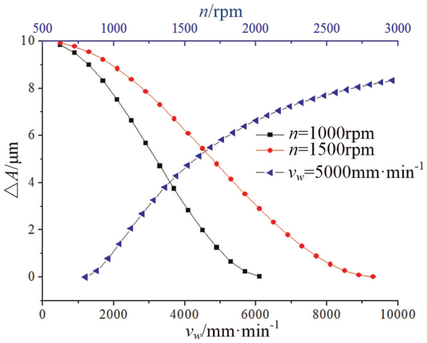
Relationship between ΔA, vw and n.
Selection of grinding parameters for X-axis waviness error
As analyzed above, the X-axis waviness error relates to wheel speed, wheel vibration amplitude, X-axis feed rate and wheel radius. Increasing the wheel speed and radius or decreasing the X-axis feed rate and amplitude of wheel vibration can reduce the waviness error. However, some issues must be considered, such as grinder accuracy, principle of grinding and grinding efficiency. For instance, increasing wheel speed leads to stronger grinding wheel vibration; too low X-axis feed rate causes low grinding efficiency and the wheel radius is confined to grinder structure. Therefore, to limit the amplitude of grinding wheel vibration, the static and dynamic balance must be done and the grinding wheel should be trued if the wheel is not in good condition. To improve efficiency, it is necessary to increase X-axis feed rate in the rough grinding process but decrease X-axis feed rate in fine grinding process to obtain high accuracy.
Characteristic of Z-axis waviness error
According to the principle of aspheric grinding, the interpolation pace in Z-axis direction is the main factor of Z-axis waviness error instead of grinding wheel vibration. As shown in Figure 7, the grinding error δz is generated when the grinding wheel interpolates dz in Z-axis direction. The Z-axis direction interpolation error δz can be calculated by 19
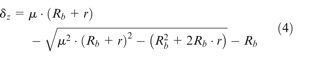
where
Z-axis interpolation error.
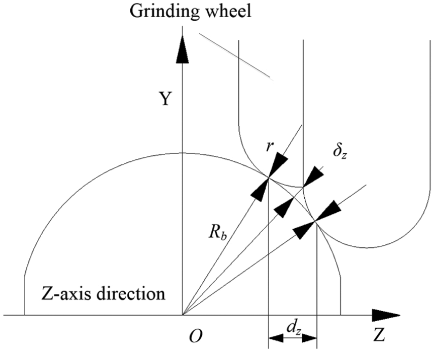
Figure 8 shows the distribution of the interpolation error δz in Z-axis direction. The marginal interpolation errors are larger than the central interpolation error, which conform to the principle of grinding. It is also shown that the larger the aspheric base radius, the smaller the interpolation error. As shown in Figure 9, the value of interpolation pace dz strongly affects the value of interpolation error δz. Using the larger wheel arc radius can decrease the interpolation error. To obtain high accuracy, the value of dz should be smaller in fine grinding than rough grinding and a wheel with large arc radius should be used.
Relationship between δz and z.
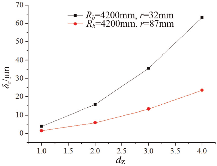
Relationship between δz and dz.
Experiments and discussion
The grinding experiments were carried out in the surface grinder 2MK1760 using grate parallel grinding method. The experimental devices are shown in Figure 10.
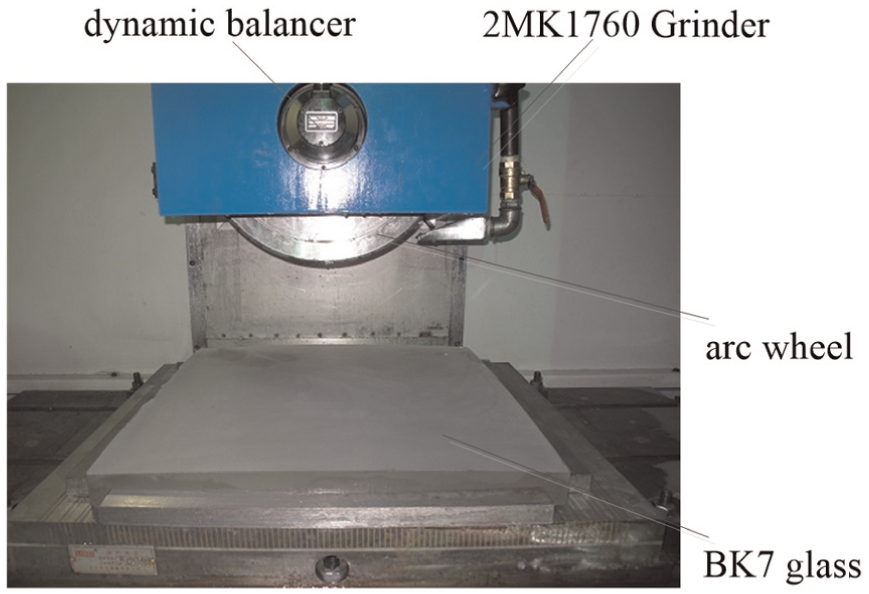
Schematic diagram of grinding device.
The equation of axisymmetric aspheric surface is expressed as
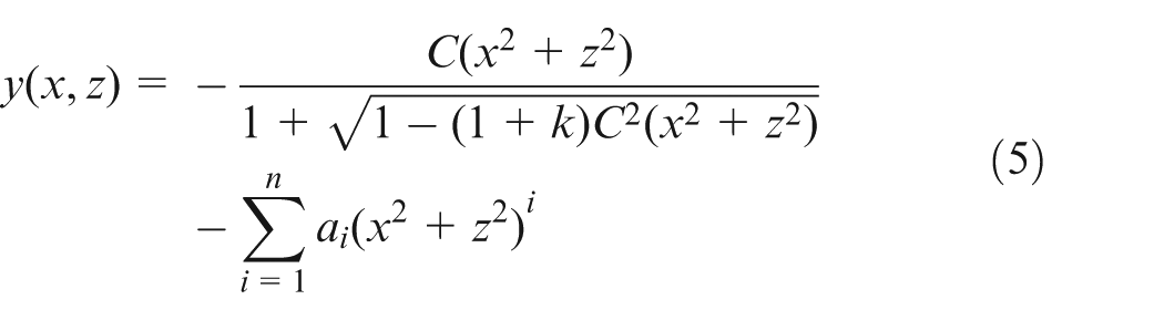
where k is the aspheric coefficient, ai is the aspheric secondary coefficient and C = 1/Rb, in which Rb is the base radius of aspheric surface.
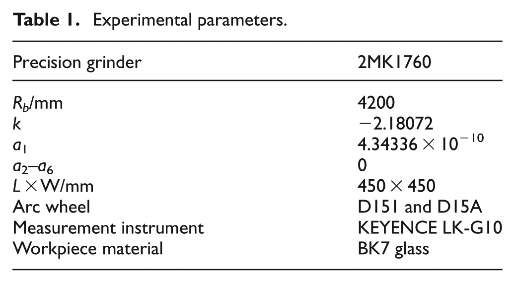
The parameters of axisymmetric aspheric surface and the grinding and measurement devices are listed in Table 1.
Experimental parameters.
On-machine measurement was applied to obtain the surface error in X-axis and Z-axis directions using non-contact displacement laser sensor. Seven sets of surface errors are measured in each direction with the same interval.
Figure 11 shows the surface errors in X-axis direction, and Figure 12 shows spectral analysis of surface error in X-axis direction. As shown in Figure 12(a) and (b), whatever type of wheel is adopted, there is a high frequency and the error period is 4.6 mm after calculation. When the values of grinding parameters are n = 1500 r/min and vw = 7000 mm/min, the theoretical period of workpiece surface trace is 4.6 mm, which is the same to result of experiment. In addition, as shown in Figure 12(c), when vw changed to 6000 mm/min, the experimental result is 3.9 mm and the theoretical period of workpiece surface trace is 4.0 mm. It is verified that the vibration of wheel is the main factor of X-axis surface waviness error.
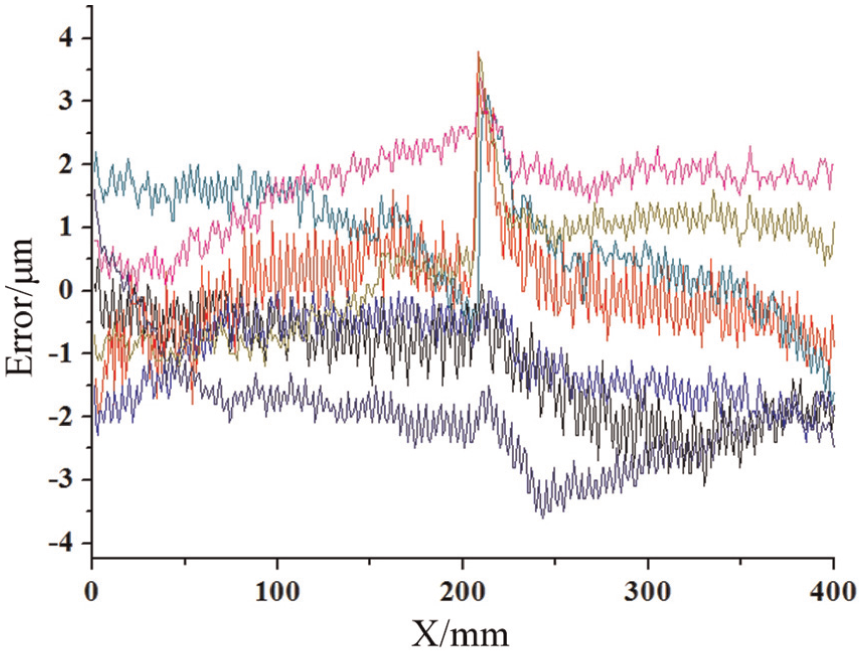
X-axis surface errors.
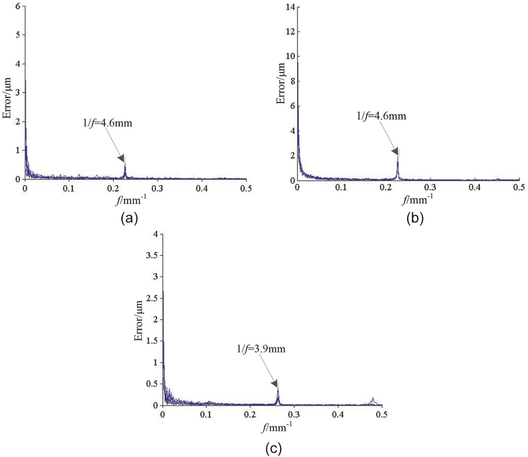
Spectral analysis in X-axis direction: (a) D15A (vw = 7000 mm/min), (b) D151 (vw = 7000 mm/min) and (c) D15A (vw = 6000 mm/min).
Figure 13 shows the surface error in Z-axis direction. Compared to surface errors in X-axis direction, the surface errors in Z-axis direction are much larger. It can be seen that the fringes in Z-axis direction are obvious and the fringe period is about 2 mm, as shown in Figure 14, which conforms to the principle of aspheric surface grinding.
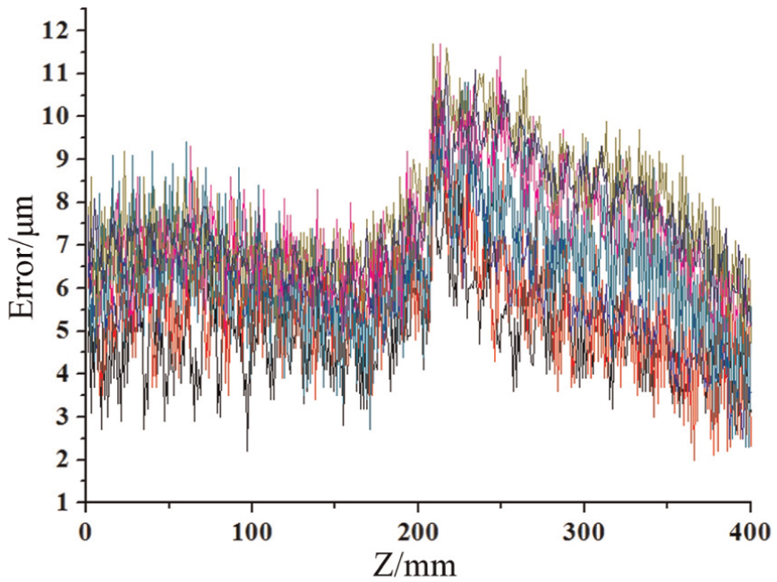
Z-axis surface errors.
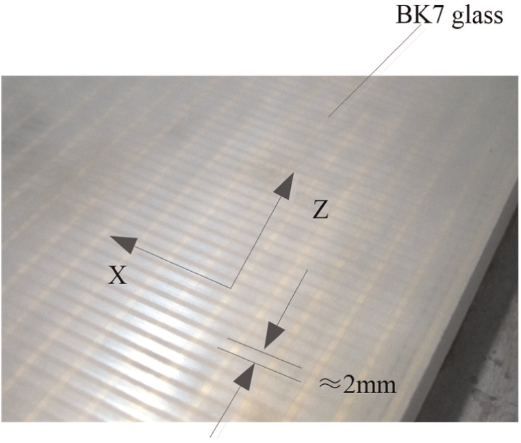
Z-axis fringes after grinding.
Figure 15 shows the spectral analysis in Z-axis direction. The spectral peak is 2.13 and 2.04 mm using different wheels, which is almost the same as the Z-axis interpolation pace. As a result, it can be summarized that Z-axis pace is the main factor that decides the value of Z-axis surface waviness error.
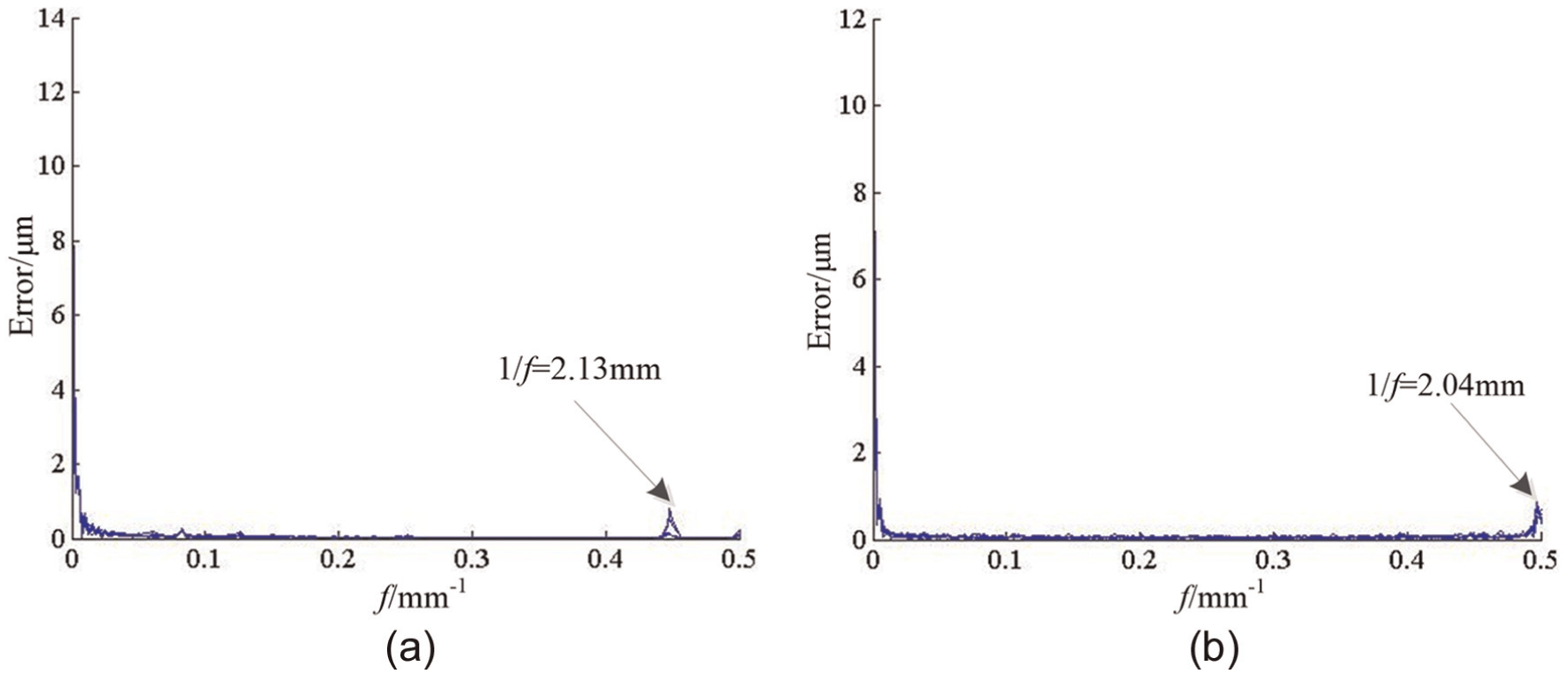
Spectral analysis in Z-axis direction: (a) D15A and (b) D151.
Due to the principle of grate parallel grinding, it is concluded that the X-axis waviness errors are formed mainly by wheel vibration and the Z-axis waviness errors are formed mainly by Z-axis interpolation pace. The waviness errors of Z-axis are much large than that of X-axis. In order to reduce the waviness error, the following steps could be taken: (1) wheel truing, (2) static and dynamic balance, (3) small Z-axis interpolation pace and (4) appropriate grinding parameters. In addition, grinding efficiency should be taken into account in fine grinding process. In general, it is a time-consuming process of large aspheric surface grinding (BK7 glass, L × W > 400 mm × 400 mm); therefore, if parameters are changed, like reducing Z-axis interpolation pace or slowing X-axis feed rate, the grinding efficiency can be lowered. In the real production, the Z-axis interpolation pace, X-axis feed rate and wheel speed are suggested as the value of 2–4 mm, 7000–10,000 mm/min and 1500 r/min in rough grinding and 1 mm, 5000 mm/min and 1500 r/min in fine grinding, respectively.
Conclusion
In this article, the surface waviness error for large axisymmetric aspheric mirror surface using grate parallel grinding is investigated. The waviness errors including X-direction and Z-direction are analyzed considering the different parameters, and the experiments to verify the cause of waviness error and to select the optimal grinding parameters were performed. The following conclusions can be drawn:
The vibration of grinding wheel is the main cause of the X-axis waviness error.
The Z-axis waviness error is much large than X-axis waviness error and the Z-axis interpolation pace is the main cause.
High X-axis feed rate and wheel speed and small Z-axis interpolation pace are suggested to reduce the waviness error. According to the grinding experiment, combined with the real production, the appropriate grinding parameters are proposed.
Footnotes
Appendix 1
Acknowledgements
The first author would like to express his deep appreciation to Xiamen University for providing the experimental space and equipment.
Declaration of Conflicting Interests
The author(s) declared no potential conflicts of interest with respect to the research, authorship and/or publication of this article.
Funding
The author(s) disclosed receipt of the following financial support for the research, authorship, and/or publication of this article: This work was supported by Xiamen University of technology’s high-tech project (YKJ14039R).