
Abstract
Based on heat conduction theory and energy conversion, the theoretical model of brake disc temperature field was established. The temperature field and equivalent Von Mises stress field distribution of brake disc during braking were investigated by using the finite element (FE) analysis. According to the thermal-mechanical coupling analysis, orthogonal optimization and analysis of variance (ANOVA) were used to optimize brake for reducing Von Mises stress on the brake disc. Results show that the temperature of a friction surface is high in the middle and low on both sides, with a large temperature gradient. In addition, the temperature and Von Mises stress form two extreme points in a direction of the friction surface circumference. Temperature and stress values decrease slowly along the direction of a brake disc rotation from an extreme value point, and decrease faster in the opposite direction. The maximum temperature of the optimized brake during braking is 473 K and the maximum equivalent Von Mises stress is 264 MPa. The main objective of this work is to reveal the influence of brake shoes structure and material on thermal-mechanical coupling of the brake disc to ensure famous strength that guarantees a longer life.
Keywords
Introduction
The mine hoist plays an important role in transporting materials and personnel. That’s one of the most important equipment in mine mining. Disc brake is an important device to ensure the safe operation of mine hoist.1,2 The braking of mine hoist drum is achieved by the friction between brake shoes and brake disc. Therefore, a safety and reliability of disc brake mainly depend on the tribological performance of their rubbing pair.3–5 During a sliding friction process of disc brakes, the mechanical energy dissipated by friction surface is converted into heat energy. 6 The heat accumulation causes surface of brake disc to heat up rapidly, resulting in thermoelastic deformation. 7 Therefore, the brake disc bears both thermal and structural loads. When the temperature of the friction surface exceeds an allowable value, it will lead to braking fade, accelerated wear of the brake disc, and a lower friction coefficient. At the same time, the thermal stress produced by temperature gradients can cause thermal cracks on the friction surface, 8 which will lead to braking failure.
The interaction between temperature and Von Mises stress fields is a typical thermal-mechanical coupling problem, and the problem has been studied by many scholars. Wang et al. 9 of Tsinghua University established a rolling bearing thermal-mechanical coupling model based on kinetic and thermodynamic theories. In addition, they analyzed the temperature and stiffness of the bearing. Thermal-mechanical coupling dynamics analysis was proposed by Liu and Lin. 10 According to this analysis, the transient and steady-state simulation analysis of the feed mechanism of CNC machine tool was carried out. They proved that the thermal-mechanical coupling effect makes the deformation of feed mechanism increase with the increase of temperature. Scholars have also investigated the thermal-mechanical coupling phenomenon of the brake from different perspectives. However, predicting how it will change is still difficult. Kennedy and Ling 11 first introduced the thermoelastic FE analysis to friction and wear analysis of disc brake back in the 1970s. Han et al. 12 used thermally coupled FE simulation to predict the thermal fatigue life and thermal stress of the brake disc. Ungureanu et al. 13 established a method for evaluating the surface temperature of rubbing pairs during a braking process of mine hoists, and numerically simulated the theoretical model for the specific conditions of actual braking work. Popescu et al. 14 developed a numerical calculation model of the brake disc temperature under emergency braking conditions in a mine hoist.
Mine hoist has the characteristics of high speed and heavy load when braking. The research on a thermal-mechanical coupling between brake shoes and the brake disc deserves attention. It will cause major casualties and economic losses if the brake fails. Existing research on the thermal-mechanical coupling of mine hoist was usually based on thermodynamic theory, with temperature and stress prediction for the brake shoes. In literature, it was observed that few of the works reported the optimization design of brake. Belhocine et al. 15 verified that the finite element analysis is an effective tool to simulate thermal-mechanical coupling phenomenon of a brake disc. They improved the service life of a brake disc by calculating structural parameters of brake disc through an optimization algorithm. The results show that it is feasible to optimize brake by finite element analysis of the thermal-mechanical coupling phenomenon.
This work considers the dynamic thermophysical characteristics of the brake disc. The distributions of temperature field and Von Mises stress field of brake disc during braking are studied. Change laws are mastered. On the basis of thermal-mechanical coupling, orthogonal design is used to optimize brake structure, which improves the safety and reliability of brake system. 16 Figure 1 shows the overall flow of this work. The solid arrows indicate an order relationship, and the dotted arrows indicate an influence relationship. The start of dotted arrow influences where it points. This research helps to reduce the temperature and stress of a brake disc, improve the safety of mine hoist. The research provides a theoretical basis for the design of a disc brake, which is of great significance to guide and ensure safe production in mine.

Overall flowchart of the entire study.
Theoretical model of heat transfer
Working principle of hoist brake
Figure 2 shows a composition of the mine hoist disc brake, including brake discs and brake bodies. Working principle of disc brake: when the brake is open, the hydraulic oil pressure is raised to push a piston, and the brake shoe is linked with a piston to release the brake disc. During braking, the brake releases hydraulic fluid. At the same time, the brake shoes are pushed by disc springs to compress the brake disc and friction torque is generated.17,18

Disc brake system for a mine hoist.
The friction between brake shoe and brake disc converts kinetic energy into heating energy. The frictional heat generated during braking is difficult to be emitted in a short period of time. Almost all of the energy is absorbed by the brake friction pairs. As a result, the brake disc temperature rises rapidly. The temperature on surface of brake disc rises sharply and thermal cracking occurs eventually, which in turn affects its tribological properties. To grasp the real temperature field and Von Mises stress field of a brake disc during braking, the heat flow density of friction surface, heat conduction, and other heat consumption must be accurately determined. This research assumes that the material composition of each component is uniform and isotropic. The effect of temperature on physical quantities such as density, specific heat capacity, coefficient of heat conduction, coefficient of thermal expansion, and modulus of elasticity is not considered. It is considered that the brake disc and brake shoes are in elastic contact. We ignore the wear between the brake disc and brake shoes. 19
Brake disc heat transfer equations
The maximum temperature reached by a brake disc depends on the heat generated and transferred. The calculation model is shown in Figure 3.

(a) Partial diagram of brake disc model and (b) A-A section of brake disc.
In a three-dimensional (3D) right angle coordinate system, the heat flow density of brake disc and brake shoe friction surface input satisfy:

Where q(x, y, t) is the heat flow density, x, y is the position of brake disc on the 3D coordinate axis, t is time, μ is the brake sub friction coefficient, p(x, y, t) is the friction surface pressure, v(x, y, t) is the relative speed of disc and shoe, F(x, y, t) is brake force of single brake shoe, S is effective contact area of single brake shoe, ω(x, y, t) is the angular speed of the brake disc, r is the equivalent friction radius between the brake disc and brake shoe.
The arithmetic means value of equivalent friction radius in contact between brake shoes and brake disc is:

Where ri is the radius of each FE cell and N is the total number of FE cells.
Under transient heat transfer conditions, the temperature rise of friction surface is obtained:

Where T is the thermodynamic temperature, ρ is the density of material, c is the specific heat capacity, and λ is the thermal conductivity.
Let the temperature rise on the two friction surfaces be equal, and the distribution of frictional heat flow density between a contact pairs is 20 :
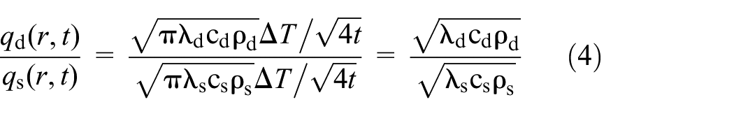
Where subscript d indicates brake disc and subscript s indicates brake shoe.
In 3D right angle coordinate system, the heat conduction equation inside brake disc and shoes are:

Where z is the position of brake disc side in 3D coordinate.
Initial moment t = 0:

Convective heat transfer of the material in air is simplified to plane heat dissipation, and the expression of its convective heat transfer coefficient is:

Where Pr is the Planck constant, ζ is the airflow rate, Ψ is the kinematic viscosity of air, and L is the wall length.
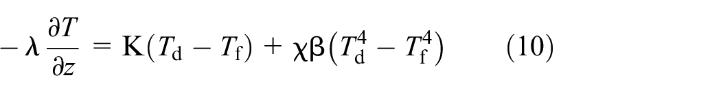
Brake disc friction surface position temperature calculation is:

When this cell on the brake disc is in contact with brake shoe, Φ = 1. When this cell on the brake disc is not in contact with brake shoe, Φ = 0. Where K is the convective heat transfer coefficient of friction surface, Td is the brake disc temperature, Tf is the air temperature; χ is the blackness of brake disc, β is the Stefan-Boltzmann constant, β = 5.67 × 10⁻⁸ W/(m2 K4). 21
The surface temperature of a brake disc in the non-frictional horizontal direction:

The surface temperature of a brake disc in the vertical direction:
The friction interface direction of a brake disc is natural heat transfer on the horizontal wall. The circumferential direction of a brake disc is vertical wall natural heat transfer.
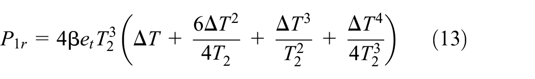
Components with temperatures above absolute zero transfer heat through electromagnetic radiation to surrounding components with temperatures below their own. The specific heat flux of radiative transfer is given by the Stefan-Boltzmann law:

Where P1r is the radiant heat flow density, T1 is the surface temperature of radiating solid, T2 is the ambient temperature, and et is the radiation coefficient.
It was observed in equation (11) that:

After calculation, the radiant heat flow density can be expressed as:
Thermal-mechanical coupling
Brake disc temperature rises during braking. The uneven thermal expansion inside the brake disc is restrained and thermal stress is generated. According to the theory of thermoelasticity, a linear strain occurs when an object is subjected to thermal expansion, but the shape remains unchanged. The relationship between thermal strain and temperature change is:

Where εt is thermal strain, γ is the coefficient of linear expansion, ΔT is the value of temperature increase.
During the braking process, the brake disc and brake shoes generate mechanical elastic strain εe and thermal strain εt simultaneously due to thermal expansion, contraction, and tensile pressure. According to the linear stress theory, the stress or strain caused by temperature change and the stress or strain caused by an external force can be superimposed. Then the total strain of brake disc and shoe is:

According to the relationship between Von Mises stress σ and strain ε:

Where E is the material elasticity matrix. Substitute equation (15) into equation (16) to obtain the total stress of brake disc and shoe as:

The balance between a cell stress σ and contact pressure p(x, y, t) at the nodes is given by:

Where B is the conversion matrix between node displacement and cell strain.
Through theoretical analysis, it was observed that the brake disc temperature variation is influenced by several factors. From the brake design point of view, combined with a thermodynamic theory, the shape of a friction surface, material properties, and distribution of brake shoes can directly change the results of thermal-mechanical coupling. Friction surface shape of a brake shoe directly affects the size of an equivalent friction radius of equation (2). Changing material of a brake shoe affects the distribution relationship of the heat flow density of equation (4). In a brake design, the software of COMSOL Multiphysics can be used to comprehensively analyze the influence of different factors on the temperature and stress distribution of the brake disc. Choose the best solution to design a brake of mine hoist.
Disc brake parameters
The brake analyzed is a type of mine hoist brake in Banji Coal Mine. Quality of the sky wheel is 53t (including the bearing seat), payload is 35t, and maximum lifting speed is 18 m/s. To investigate the temperature and stress distribution of a brake disc under extreme braking, a 3D model was drawn from its original dimensions. The brake disc dimensions are shown in Table 1. The braking condition at the maximum operating speed was selected as a boundary condition.
Brake disc and connecting plate size parameters.

Belhocine and Abdullah 22 carried out a numerical simulation of transient thermal analysis and static structural analysis by using the sequential coupling method. By changing the material to observe the change of brake disc thermal properties, and then get the best thermal properties of the material. It shows that the thermal-mechanical coupling analysis is effective and the material can affect temperature of a brake disc. The performance parameters of brake disc and brake shoe materials 23 are shown in Table 2. The set braking deceleration is 3 m/s2 and the braking time is 6 s. In the calculation, all brake shoes are fixed and the brake disc is rotating. It is assumed that the pressure distribution between brake shoes and brake disc is uniform. Brake shoes deformation mainly occurs in z direction during braking. Therefore, the displacement of constrained brake shoes in x and y direction are zero. In z direction are free.
Brake disc and brake shoe material performance parameters.

Analysis of simulation results
Mesh information of finite element
In this work, COMSOL Multiphysics software was used to conduct finite element calculation of transient thermal analysis and structural analysis simultaneously through thermal-mechanical coupling. The brake was modeled in COMSOL according to the parameters in Tables 1 and 2. Heat Transfer in Solid and Solid Mechanics physical fields were added to the components. The software calculates the heat transfer of brake disc and brake shoes through transient heat transfer equations. Add a Thermal Expansion Multiphysics coupling node to add an internal thermal strain caused by changes in temperature. The Thermal Expansion node coupled the Heat Transfer in Solid and Solid Mechanics interfaces together. Rotating motion was added to the brake disc. To study the stress and temperature distribution, the interaction between the two physical fields needs to be considered at each incremental step. In order to achieve this goal, Full Coupling was selected as the solution method under COMSOL Transient Solver. A boundary constraint was added to the brake shoe to keep only the unique degree of freedom along the normal direction of the brake disc.
The influence of thermoelastic deformation was considered in the calculation. The thermal strain term caused by temperature change can simply be added to the stress-strain relationship based on the generalized Hooke’s law. Therefore, the total strain of thermoelastic deformation can be calculated by the following equation:

Meshing involves division of the entire of a model into small pieces called elements. The heat flux density and Von Mises stress described in this work are related to mesh information. In FE modeling, a finer mesh typically results in a more accurate solution. 24 However, as a mesh is made finer, the computation time increases. For our problem, we refine the mesh at certain areas of the disc geometry on friction rubbing surface where the gradients are high, thus increasing the fidelity of solutions in the region. Also, this means that if a mesh is not sufficiently refined then the accuracy of the solution is more limited. Thus, the calculation accuracy and time cost should be taken into consideration when selecting the number of cells. In order to find the appropriate number of cells, improve the quality of cells and obtain effective results, it is necessary to analysis the independence of cells.
The 3D model established in COMSOL has meshed. The contact part between the brake shoe and brake disc was partially refined. Figure 4 shows the maximum temperature of brake disc under eight groups of the same working conditions and different mesh numbers. When the number of cells exceeds 4.5 × 10⁵, finer cells have no greater temperature change. Therefore, this group of cell numbers is selected for calculation. Figure 5 reports the FE mesh used in the analysis.

Independence analysis of mesh.

Mesh model.
Brake disc temperature analysis
At the end of braking (t = 6 s), the brake temperature distribution on the rectangular friction surface is shown in Figure 6. The figure records a maximum temperature of 468 K. During braking, the friction surfaces heat accumulation and temperature rise. This hot strip with hot spots gradually migrates to the inner radius. Therefore, the friction surface of the brake disc and connection surface both had different degrees of temperature rise.
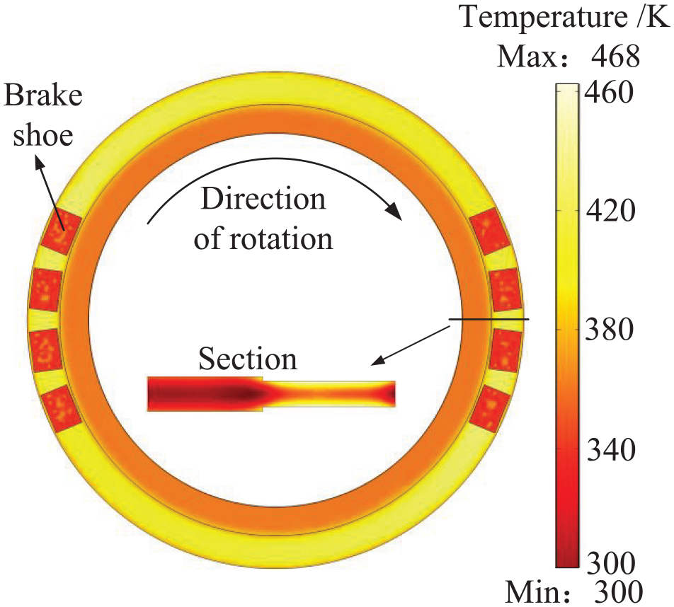
Brake disc temperature distribution chart (t = 6 s).
Moreover, with the continuous friction of brake, the friction surface continues to heat up, forming a ring-shaped high-temperature area. A large temperature gradient exists between the high-temperature zone and connection surface. The heat flow density is highest at the friction area. Therefore, the temperature rises fastest in the friction area. Non-frictional area heat loss, temperature decreases in the direction of brake disc rotation. The cross-sectional temperatures in Figure 6 indicate that the boundary conditions have little effect on the internal temperature rise of a brake disc. Heat conduction mainly enters material along the direction perpendicular to the friction surface. The temperature gradient and amount of change along the z-direction during braking are greater than along the other two directions.
The temperature of B transversal in Figure 3(a) changes with time as shown in Figure 7. The temperature of B cut-off line is distributed with high middle and low sides. The outer edge and connection surface temperature are below the equivalent friction radius of a brake disc. Mainly as a result of the middle part is a friction position, the heat flow density is high, and both sides dissipate heat faster through heat conduction, convection, radiation. Figure 7 shows the different temperature rises and inconsistent heat flow densities at various points along the radial direction in the friction region. This research considered the influence of brake shoes friction along with the radial distribution on the temperature field distribution, which is more consistent with the actual working conditions. It can also be seen in Figure 7 that the temperature of the B cutoff rise rapidly with time first. At the end of the braking section. The brake disc speed is slower. Heat is dissipated more than generated, and the brake disc temperature decreases.
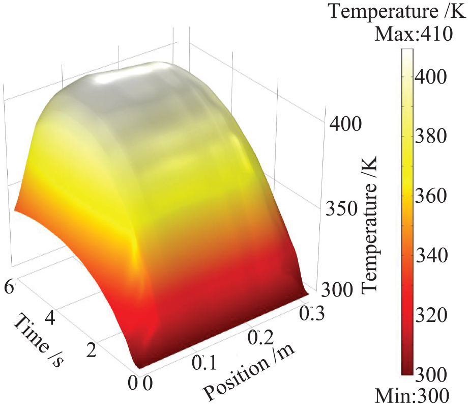
B cutoff temperature variation chart.
Thermal-mechanical coupling analysis
The uneven distribution of temperature makes the brake disc’s friction area in radial and axial thermal expansion. Therefore, large thermal stress has been generated. The temperature causes a thermal shock and thermal fatigue to the brake disc material. In severe cases, the yield strength of the brake disc material may be exceeded, leading to cracks in the brake disc. Figure 8 shows the Von Mises stress distribution of the brake disc and brake shoes under braking conditions with direct coupling to the temperature shown in Figure 6. From Figure 8, it can be seen that stress on the surface of a brake disc is distributed in a circular pattern in the circumferential direction. The brake disc and brake shoes’ contact extrusion area stress value are the largest, decreasing along the direction of rotation of a brake disc. The instantaneous maximum equivalent Von Mises stress is 304 MPa. This is because of the braking process, the brake disc and brake shoes contact extrusion area at the maximum temperature value. Uneven temperature distribution leads to the formation of a large temperature gradient in the axial and radial directions of rubbing pair. At this time, a large amount of heat is too late to transfer outwards and thermal stress is generated. Thermal stress is superimposed here with compressive stress and frictional shear stress. Therefore, the equivalent Von Mises stress concentration phenomenon occurs at the contact extrusion of a brake disc and brake shoes. By comparing Figures 6 and 8, it can be found that the stress distribution has a high similarity with the temperature distribution. The interaction recorded in thermal-mechanical coupling analysis is very significant compared with the structural stress only considered under the same braking conditions. 24

Brake disc Von Mises stress distribution chart (t = 6 s).
Temperature and stress changes were observed by changing the structure of the friction surface. Analysis of the effect of different shaped brake shoes on the temperature and stress of a brake disc. Rectangle, diamond, and circular friction surfaces of brake shoes are selected. The friction surface structure of brake shoe is shown in Figure 9. The friction surfaces of brake shoes are different but the area remains the same. The temperature change of brake disc is shown in Figure 10 and the stress change is shown in Figure 11.
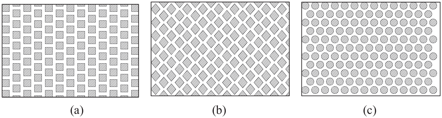
Different friction surfaces: (a) rectangle, (b) diamond, and (c) circular.

Brake disc maximum temperature change chart.

Drake disc maximum stress change chart.
In an initial stage of braking, the speed of a brake disc is high. As can be seen from Figure 10, the rate of frictional heat generation is much higher than the rate of heat dissipation due to convective heat transfer and heat conduction, resulting in a sharp rise in brake disc temperature. As for braking proceeds, decreasing the speed of a brake disc and heat flow density input. In contrast, as the brake disc temperature rise, the rate of thermal convection, conduction, and radiation heat dissipation continues to accelerate. In the middle of braking period, the rate of temperature increase slows down. After crossing the maximum temperature threshold, the speed of heat input on the friction surface is transformed with its heat conduction, heat convection, and radiation heat dissipation energy speed. The temperature of points located on the surface within the friction rings gradually decreases. And the maximum temperature of a brake disc gradually decreases.
Comparing Figures 10 and 11, it can be seen that the brake disc temperature and Von Mises stress value both show a gradual increase with the extension of the braking time. When they rise to the maximum value and then gradually decrease. The temperature and stress distributions on the surface of the brake disc are consistent, with a circular band distribution in the circumferential direction. In the brake disc and brake shoes contact extrusion area temperature maximum, stress maximum also occur here. This shows that the generation of thermal stress is related to the temperature value and temperature gradient, which further proves that the temperature field and stress field have coupling characteristics.
Figures 10 and 11 show that different friction surfaces of brake shoes have different temperatures and Von Mises stress behaviors. The main reason for this phenomenon is that the effective arc length of a friction surface is different. The transversal of friction circle on the friction surface of brake shoe is called effective arc length, as shown in Figure 12. The effective arc length can be changed by different shapes of friction surfaces and different distribution rules. The longer effective arc length of a friction circle means that more time is spent rubbing at that circle and more heat is generated. If the effective arc length difference between the friction circles is large, the friction surface will have a large temperature difference and uneven thermal expansion, resulting in greater thermal stress. Therefore, brake design should be considered to improve friction surface structure and distribution, improve the brake disc temperature gradient, and reduce stress.

Schematic diagram of effective arc length.
Orthogonal optimization
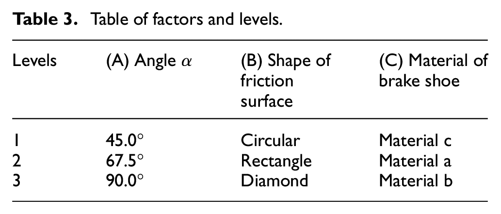
To further optimize the brake structure in an attempt to reduce the brake temperature and stress. Multi-objective optimization was carried out through the finite element simulation by COMSOL Multiphysics. Optimizing the brake examines two indexes: maximum temperature and maximum Von Mises stress. Both indexes are as small as possible. Based on certain expertise and experience in brake design, it was decided to select three factors25,26: Brake shoes distribution angle α, friction surface shape of brake shoes, and brake shoes material. Each factor has three levels, and the specific data are shown in Table 3. Ensure that different shapes of friction surfaces have the same friction area. The performance parameters of materials a, b and c are shown in Table 2.
Table of factors and levels.
Orthogonal design selects some representative points from the overall experiment according to orthogonality. These representative points have the characteristics of uniform dispersion and uniform comparability. Orthogonal design can achieve a result equivalent to a large number of comprehensive tests with the least number of tests. Therefore, orthogonal array design is an efficient, rapid, and economical method of multi-factor experimental design. 27 The selection of an orthogonal table is based on the number of factors and levels, usually requiring that the number of factors is not greater than the number of orthogonal table columns. Levels number corresponds to levels number corresponding to the orthogonal table. On the premise of meeting the above conditions, we can choose a smaller table. If the numbers of factors are less than the number of orthogonal table columns, an empty column can be used as the error column and placed in the middle column or later column. In this research, a combination of 3 factors and 3 levels was determined, without considering the interaction between factors. The research uses an orthogonal table of L9(34) to carry out the numerical simulation. 28 The table header design, optimization scheme, and calculation results are shown in Table 4.
Orthogonal optimization scheme and calculation results.

Table 5 shows a visual analysis of the calculated results. The influence of each factor on the index was determined in order of priority. The optimal solution was chosen. The magnitude of the effect of changes in factor levels on the range of indexes is observed by calculating the extreme differences. The larger Range, the greater impact of levels selected under that factor has on the indicator. Therefore, it is clear from Table 5 that the factor that has the greatest influence on the temperature index is A. Factors in order of priority are A, C, B. And the preferred solution is A3C2B2. The factor that has the greatest influence on the stress index is A. The main order of the factors is also A, C, B, but the preferred solution is A1C3B2. The results of intuitive analysis showed an excessive variation between ranges, which is caused by the large difference between the selected levels. Chosen level numbers are too different to easily estimate the magnitude of an error. The importance of the influence of each factor on the calculation results cannot be accurately estimated. To solve the above problem, the calculated results were further subjected to an imitation ANOVA, and the ANOVA results are shown in Table 6.
Visual analysis of optimization results.

ANOVA of optimization results.

ANOVA can determine the degree of influence of each factor on the test index. The sum of squares of the total sample bias was decomposed into the sum of squares of the bias due to each factor and the sum of squares of the bias due to random error in the experiment. The ratio of the mean sum of squared deviations of each factor to the mean sum of squared deviations of the error was denoted as F-value. This value reflects the magnitude of the influence of each factor on the test results. Find out the critical values F0.05(2,2) = 19. The degree of significance of factors to indicators is indicated in the last column of Table 6. The more * there are, the greater impact.
Through visual analysis and ANOVA of the calculated results, two groups of superior solutions were identified as A3C2B2 and A1C3B2. The computational set needs to be increased and compared with the better solution of the orthogonal solution. A better solution needs to be further verified. Figure 13 shows the comparison of the maximum temperature points of A3C2B2 and A1C3B2 with the better performing schemes No. 3 and No. 8 in Table 4. Figure 14 shows a comparison of the Von Mises stress in the optimal scheme and orthogonal table.
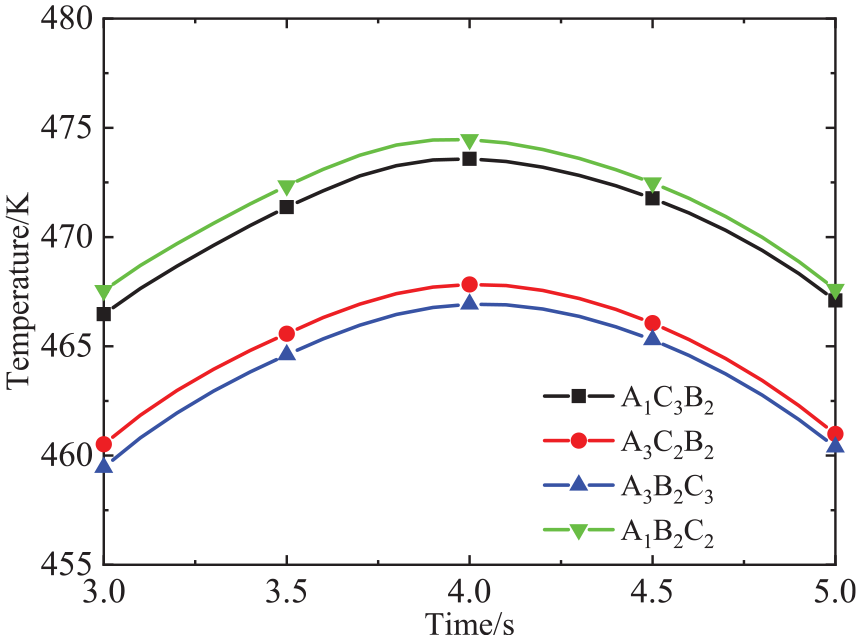
Comparison of the temperature highest point.

Comparison of the stress highest point.
It can be seen from Figures 13 and 14 that neither optimal scheme nor control group can obtain the lowest temperature and Von Mises stress at the same time. In the factors causing brake failure, Von Mises stress is more important than temperature. The purpose of reducing brake disc temperature is also to reduce Von Mises stress. The weight of stress is greater than that of temperature in results analysis. Therefore, the optimal solution is determined to be A1C3B2. Optimal design parameters of the brake disc obtained are friction surface of rectangle, the angle of 45°, and material of b. The optimized brake has a maximum temperature of 473 K and a maximum Von Mises stress of 264 MPa during braking.
Conclusion
Thermal-mechanical coupling phenomenon of mine hoist brake disc was studied in this work. We optimized a brake by changing the brake parameters to reduce temperature and Von Mises stress. Combined with dynamic physical characteristics of brake and change of heat flux, a theoretical model of the 3D transient temperature field and Von Mises stress field of mine hoist moving disc were established. Thermal-mechanical coupling finite element analysis is an effective tool to simulate the operating conditions of the brake disc, efficiently used in the present work.
A detailed finite element model was used to study the temperature and Von Mises stress distribution of brake disc during braking. The simulation results showed that the temperature of a brake disc increases first and then decreases. The friction surface accumulates a lot of heating. Due to the delayed heat diffusion rate, a large temperature gradient is generated. High-temperature and high-stress areas are distributed in a circular band on the friction surface of brake disc. Temperature decreases from the friction position in the direction of brake disc rotation. The results are consistent with the phenomenon shown in literature of others. It is worth noting that the maximum temperature is located in the contact extrusion area between brake disc and brake shoes. The maximum stress also occurs here. The distributions of stress and temperature are still consistent after changing the brake shoe structure, which shows that the brake disc temperature field and stress field have a mutual coupling effect. It can be seen from the calculation results that different materials or different structures of brake shoes will affect the temperature and stress values.
The effects of temperature and Von Mises stress were analyzed by varying a variety of structural parameters. The influence of brake shoes structure, distribution, material on maximum temperature and maximum stress was investigated. The orthogonal optimization method was used to design nine groups of solutions, which simplify the optimization steps and improve the optimization efficiency. The finite element model can effectively simulate the thermal-mechanical coupling of a brake. The simulation significantly reduced the cost and time required for physical experimentation. In ANOVA of optimization results, high F-value less than 0.05 revealed that the present statistical and regression model is significant. Here the influences of different design parameters on the temperature and stress of the disc have been studied. Also, the set of optimal design parameters were presented. Optimal design parameters of the brake disc obtained using orthogonal optimization are friction surface of rectangle, the angle of 45°, and material of b. The optimization results have been verified by the confirmation simulation test. The temperature and Von Mises stress of optimized brake are reduced effectively. It has a certain reference value in engineering applications. It provides a theoretical basis for the optimal design of mine hoist disc brake.
This study also has some limitations. The influence of continuous braking on the moving disc of mine hoist mechanism is not considered. Due to the limitation of conditions, no experiments were carried out to verify the error between simulation and actual. Improving these limitations can further understand the influence of brake structure of mine hoists on thermal-mechanical coupling.
Footnotes
Appendix
Acknowledgements
The authors thank the anonymous reviewers for their critical and constructive review of the manuscript.
Handling Editor: Chenhui Liang
Declaration of conflicting interests
The author(s) declared no potential conflicts of interest with respect to the research, authorship, and/or publication of this article.
Funding
The author(s) disclosed receipt of the following financial support for the research, authorship, and/or publication of this article: This work is supported by the National Natural Science Foundation of China (51904009), China; the Major Project of Natural Science Research in Universities of Anhui Province (KJ2021ZD0052), China; the Open Foundation of Anhui Key Laboratory of Mine Intelligent Equipment and Technology (ZKSYS202102), China; the University Synergy Innovation Program of Anhui Province (GXXT-2020-061), China.