
Abstract
As the final executor of the braking system of coal mine hoists, the disc brake directly affects the safety and reliability of mine hoists. Aimed to the problem of failure of hoist disc brake, according to its structural characteristics and functional requirements, this article proposes a disc brake that monitors positive brake pressure in real time and has a certain brake fault diagnosis function and develops a prototype. Based on SolidWorks, its virtual prototype model is established, and its finite element model is established by ANSYS Workbench. The static and dynamic simulations are performed on the entire disc brake and key components to obtain overall vibration characteristics and mechanical characteristics. Prototypes of disc brake and sensors are machined to perform test experiments to measure the performance, and experimental data are analyzed in conjunction with theories. The experimental results show that the disc brake can realize real-time effective monitoring of the positive brake pressure. It has the function of fault diagnosis, and its strength and stiffness meet the requirements with lower cost. The correctness and effectiveness of the proposed structure scheme are verified.
Keywords
Introduction
The disc brake of mine hoist is the ultimate executor of safe parking of mine hoist. Its safe and reliable work can ensure the safe operation of mine hoist. But the failure of brake will cause accidents such as overwinding, rope breaking, tank falling into the bottom of the well, or rushing to the skyscraper, which will cause great losses.1–3 Therefore, it is necessary to study the application of disc brake with innovative structure and abundant functions in the field of mine hoist. With the rapid development and increasingly fierce competition in the world, the development of disc brake of mine hoist tends to be more reliable, safer, and more intelligent.4,5 The way to improve the reliability of disc brake has always been an important issue in the development process. Many works focus on improving the reliability of disc brake.
In order to improve the reliability of disc brake of mine hoist, some scholars have studied the structure design of disc brake as a breakthrough point. SR Ge et al. 6 designed an adaptive boosting and compensating brake for mine hoist, to avoid insufficient positive brake pressure when mine hoist brakes. On the basis of the original disc brake, the positive pressure of the brake on the brake disc is increased by opening an oil inlet hole on the back cover of the oil distribution to supply pressure oil to the compensating pressure chamber. The constant backlash between friction pads and brake discs is an important factor affecting brake safety. LP Li et al. 7 designed a constant-opening hydraulic disc brake with automatic compensation and wear display, which can ensure that the backlash between friction pads and brake discs remains unchanged. M Feng 8 put forward the solution of cylinder rear disc brake to overcome the defects of cylinder front disc brake and carried out a comprehensive test on the performance of the brake, which increased the reliability of brake. In order to ensure the effective work of disc brake, J Chen 9 and XQ Gao 10 transformed the internal structure of disc brake into a sensor to monitor the disc spring force. When braking, the disc spring force is equal to the positive braking pressure, which can indirectly monitor the positive braking pressure and greatly reduce the risk of brake failure.
In addition, some scholars studied the monitoring methods of disc brake failure of mine hoist and prevented major accidents and improved the reliability of brake. DK Zhang et al. 11 studied and designed a disc brake for hoist, which can diagnose the performance failure caused by brake shoe wear, disc spring fatigue fracture, and piston jamming in time. In order to ensure the braking performance of disc brake, K Xiao and S Fu 12 designed a monitoring system for brake failure of mine hoist brake, which monitored oil pressure, brake shoe clearance, and brake shoe temperature in real time by sensors. Previous studies9–12 aims at monitoring the key parameters of disc brake. If the parameters are abnormal, the alarm can be given, and the staff can check and troubleshoot in time to ensure that the disc brake of mine hoist works reliably. In order to further improve the brake performance and reliability of disc brake, some scholars put forward fault analysis method. For example, YX Hao 13 proposed using fault tree analysis (FTA) method to analyze the fault causes of disc brake system of mine hoist. MJ Jin 14 introduced the fuzzy set theory into the FTA of disc brake of hoist and established the fuzzy fault tree. Q Wang and XM Xiao 15 analyzed the typical failure mechanism of the brake system by establishing the brake performance analysis model. JS Bao 16 uses artificial neural network technology to build an intelligent prediction model.
In recent years, the research of many scholars has improved the reliability of mine hoist, among which the research of literature9,10 has made a great contribution to improving the reliability of disc brake of mine hoist. The health of brake can be evaluated by indirect measurement of positive brake pressure. However, it has certain defects. If the brake is jammed when the brake disc is 0.01 mm away from the brake shoe during the braking process, the brake disc is not tightly attached to the brake disc at this time. The actual positive brake pressure is zero, and the disc spring force exists and is normal. By disc spring force sensor, the brake is healthy. In fact, the brake is unhealthy. The failure of the blockage cylinder cannot be safely immobilized, and the failure condition cannot be evaluated by the disc spring force sensor. Under the condition that the disc spring force is normal, there is still a lack of brake force which results in frequent occurrence of brake accidents.17,18 The existing brake technology and product level cannot meet the requirement in terms of structure principle and performance index.19–21 In view of the present situation, this article presents a disc brake with diagnosis of brake failure and real-time monitoring of positive brake pressure. By monitoring the brake clearance, disc spring force, and positive brake pressure parameters, the positive brake pressure can be realized. Effective and accurate monitoring of positive brake pressure and fault prediction is of great significance to improve the safety and reliability of large mining equipment.
Design and analysis of mechanical structure
Application background and design requirements
The mine hoisting system is used for mining coal, iron ore, and so on. It mainly includes hydraulic station, brake, depth indicator, roller, reducer, and motor, as shown in Figure 1. The motor drives the drum through the reducer, and the drum is driven by the wire rope to lift the container up and down in the mine to complete the transportation task. The brake system is composed of hydraulic station and disc brake, which is the final part of the braking system to complete the braking task.

Composition of the hoist system: (1) hydraulic station, (2) depth indicator, (3) roller of the hoist, (4) reducer, (5) motor, and (6) brake.
The common disc brake mainly includes shell components and hydraulic components, and its structure is shown in Figure 2. The working principle is to realize the releasing brake and contracting brake by the hydraulic pressure affecting the spring force of the disc spring. In order to make the brake disc to not produce additional deformation and the spindle to not bear additional axial force, the disc brakes are used in pairs and each pair is installed on both sides of the brake disc. Multiple brakes can be arranged for each hoist according to the required braking torque.
Common disc brake structure diagram: (1) shell components of brake, (2) disc spring, (3) disc spring seat, (4) ring, (5) “V”-shaped seal ring, (6) leakage tubing interface, (7) YX-shaped seal ring, (8) piston, (9) seal ring, (10) back cover, (11) connecting bolt, (12) piston inner sleeve, (13) hydraulic cylinder head, (14) pressure tubing interface, (15) adjusting nut, (16) hydraulic cylinder, (17) liner with cylinder, (18) brake tile, and (19) brake disc.
Although the disc brake has been improved qualitatively in structure, function, and usage, it cannot effectively avoid the brake accident caused by its failure. Most of the accidents in the mine hoist, such as over-rolling, pier tank breaking, rope breaking, and sliding, are all related to braking failure and the lack of positive braking pressure. The large gap between brake shoes and brake discs and the failure of disc springs, such as fatigue, fracture, and small preload, cause insufficient positive brake pressure. Therefore, how to accurately and effectively monitor positive braking pressure is of great practical significance and value for mine safety production.
Structural scheme and working principle of disc brake for monitoring positive brake pressure
Considering the characteristics of common disc brakes, it is optimized on the basis of the original brake structure, and a disc brake which can diagnose the brake fault and monitor the positive brake pressure in real time is designed. The optimized structure is composed of disc spring force sensor, positive brake pressure sensor, disc spring group, piston, hydraulic cylinder, bearing sleeve, tile, and other components, and its internal structure is as shown in Figure 3.

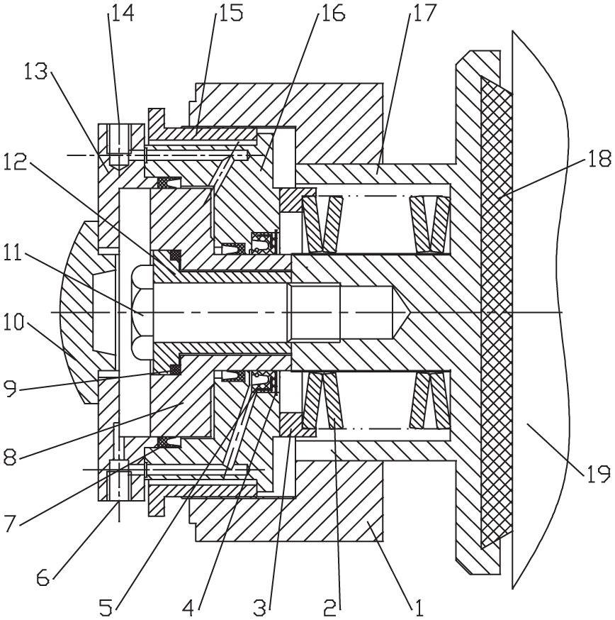
Brake structure diagram with diagnostic brake failure and monitoring braking force: (1) cylinder liner; (2) brake body; (3) disc spring group; (4) disc spring force sensor; (5) adjusting nut; (6) out of oil pipe interface; (7) piston; (8), (15), and (16) seal ring; (9) piston inner sleeve; (10) big nut; (11) back cover; (12) positive braking pressure sensor; (13) hydraulic cylinder head; (14) intake pipe interface; (17) hydraulic cylinder; (18) “V”-shaped seal ring; (19) cir-clip; (20) displacement sensor; (21) brake tile; (22) disc spring support ring; (23) screw; (24) protection bucket; and (25) sluice.
As shown in Figure 3, the inner disc spring seat is designed as a disc spring force sensor with the same size and direct replacement. It is used to monitor the disc spring force in real time to judge the state of the disc spring group. The original connection bolt is optimized to be the brake pressure sensor. The sensor is responsible for real-time monitoring of the braking pressure. The column is removed in the middle of the original cylinder liner and connected by the bolt with the brake pressure sensor, and the disc spring force is designed to transfer the disc spring force to the elastic cylinder between the right and the central shoulder of the positive pressure sensor. A plate spring force is designed to transfer the disc spring force to the elastic cylinder between the right and the central shoulders of the positive pressure sensor. The eddy current displacement sensor is set up in the corresponding position of the brake body and the liner of the barrel, which can monitor the sluice gap of the brake shoe and the brake disc in real time and the deflection of the sluice plate in real time, so as to provide a guarantee for the accurate monitoring of the clearance value. Based on the premise that the disc spring force is equal to the positive pressure of the brake under the ideal braking state, the data monitored by the two sensors are compared in real time. When the value is equal, the brake pressure is normally applied to the brake disc and the brake performance is normal. When the value is not equal, the machine stops running, and the specific cause of the fault is diagnosed by the specific value of the eddy current sensor and the specific condition of the two pressure sensor data.
Fault diagnosis process of brake
Comparing the values monitored by the two pressure sensors in the complete braking state of the brake operation: (1) the value is equal and normal and then the function of the brake can be judged to be normal. (2) The value is equal but less than the normal value and the machine stops running and is checked at this time. If the value is larger than the value specified in the coal mine safety regulations, when the clearance of the brake disc is adjusted, if the gap is normal, it can be judged to be the fatigue or fracture of the disc spring group. (3) The value is equal but greater than the normal value, and then, it can be judged to be too high in the pre-pressure of the disc spring. (4) The value is not equal. The force of the disc spring is normal and is greater than the positive pressure of the brake, which can be judged as the excessive internal pressure of the brake. (5) The value is not equal, and the disc spring force is greater than the normal value. It can be judged that the disc spring is stuck because of obstruction. Its fault diagnosis process is shown in Figure 4.

Fault judgment flow chart of the disc brake.
This article is organized as follows. In section “Finite element analysis of key components of brake,” three-dimensional (3D) model, meshing division, and load condition analysis of key components and the result are stated. In section “Modal analysis of disc brake,” virtual prototype model and finite element model are established, and the results of common modal analysis and prestressed model are compared. In section “Experimental verification,” sensors’ static characteristics are checked and the results of the test are analyzed in detail. In section “Conclusion,” we draw conclusions.
Finite element analysis of key components of brake
The 3D model establishment and meshing division of key components
The optimized disc brake has been modified to remove the central cylindrical structure of the original cylinder liner, adding the bearing sleeve and creating the design of the disc spring force sensor and the braking pressure sensor. In order to ensure the safety and reliability of the structure, the ANSYS Workbench software is used to carry out the statics of finite element analysis on the key components of the above changes. The virtual prototype model of the disc spring force sensor, the brake pressure sensor, the bearing sleeve, and the liner is established by using the 3D modeling software SolidWorks, as shown in Figure 5.

3D model of key components.
An analysis project is created—the solution type is Static Structure and the solver type is ANSYS solver. The material of the sensor is 40Cr, and the material of the bearing sleeve and the lining plate is 45 steel. According to their material properties, relevant settings are made in the material library, as shown in Table 1.
Material properties of key components.

After the setting is completed, the grid is divided to form the model. In order to improve the accuracy of the analysis, the relevance value is set to 100 and the relevance center remains the same. Finally, the grid partition effect of each component is obtained, as shown in Figure 6.

Grid division of key components.
Load condition analysis of key components
In the work of the disc brake, the stress of its internal components is mainly related to the hydraulic pressure of the hydraulic station and the stiffness of the disc spring. The main parameters are shown in Table 2.
Main related parameters.

Inside the disc brake, one end of the disc spring force sensor is supported on the hydraulic cylinder and the other monitor the disc spring force in real time. When the brake is in the loose state, the compression amount of the disc spring group is the maximum, and the disc spring force sensor is the maximum force state at the moment. It is known that the brake oil pressure of the disc brake is 5 MPa. The internal piston diameter is 140 mm and the piston diameter is 60 mm. The pressure value produced by oil pressure during fully loosening is calculated from the formula
The force condition of the positive brake pressure sensor is different during the opening and closing of the brake. When the brake is opened, the thin cylinder part bears the tensile stress; when the brake is closed, the thick cylindrical part (the strain patch fitting area) bears the pressure stress. In full sluice, the disc spring force is equal to the oil pressure, and the compressed disc spring group applies the disc spring force to the shaft shoulder of the power sensor through the bearing sleeve, so the tension of the thin cylinder part is equal to the oil pressure of 62.8 kN under the state of complete sluice. The brake shoe is not in contact with the brake disc at this point, so the rough cylinder end is not subjected to force. In fully closed condition, the positive brake pressure is equal to the oil pressure minus the disc spring force. The coal mine safety regulations stipulate that the sluice gap must be less than 2 mm. Under the constant condition of other parameters, the smaller the clearance value, the greater the positive pressure value of the brake. For safety, the clearance value of the sluice gate is 1 mm, the stiffness of the disc spring is k = 68.97 t/mm, and the compression of the eight disc springs at the time of the complete sluice is
The inner end face of the bearing sleeve is supported on the axle shoulder of the brake pressure sensor. The upper end face of the large disc is supported by the disc spring force of the disc spring group. When the brake is in the loose state, the bearing sleeve is the maximum force state, and the force is 62.8 kN at this time.
The inner face of the liner is connected with the brake pressure sensor through the bolt, and the outer end face contacts with the brake disc in the brake state. At this time, it is the maximum force state of the lining plate. When the brake clearance is 1 mm and when the brake is normal, the force is 54.2 kN.
Result analysis of key components
According to the contacting fixed condition of the key parts inside the brake, the corresponding constraint conditions are applied. Considering the stress analysis above, the corresponding load conditions are added. Equivalent stress and total deformation are added to the post-treatment. Then, we obtain stress cloud and deformation cloud of each component. In order to show the deformation trend of the sensor, the deformation effect of the cloud image is amplified and the undeformed position line diagram of the sensor is added, as shown in Figure 7.

Stress and deformation clouds of key components: (a) positive pressure sensor (compression), (b) positive pressure sensor (tensile), (c) spring force sensor, (d) bearing sleeve, and (e) lining plate.
According to the stress and deformation cloud diagram of each key component, the specific numerical analysis is summarized, as shown in Table 3.
Specific numerical situation of the analysis results of key components.

According to Table 3, the maximum variable value of the brake pressure sensor at the closing time is 0.036 mm. The shape variable of the lining plate at the closing time is 0.12 mm, and the maximum variables of the other components are all within this range. The deformation amount is safer to meet the safety requirements. The safety coefficient at the time of tension is 2.04, and the safety factor of the lining plate is 3.2, when the closing force is forced. The safety factor of the other components is within this range, so the strength is fully satisfied with the safety requirements.
Modal analysis of disc brake
Establishment of the virtual prototype model and the finite element model
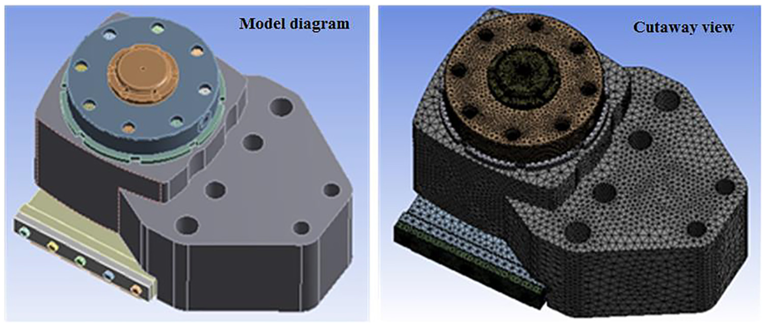
Due to the phenomenon of vibration in the operation of the hoist, the brake needs to repeat the loosening and closing movements of the drum with the continuous lifting of the lifting items. During the closing process, when the brake shoe is in contact with the brake disc, the vibration of the drum and the contact of the brake shoe and the brake disc will cause more complex vibration of the disc brake device. Therefore, the mode analysis of the brake needs to be carried out to obtain the modes and natural frequencies, and the ANSYS Workbench is still used to carry out the routine of the brake. Modal analysis (sluice state) and modal analysis with prestress (closing state) are used to determine whether the excitation frequency of the optimized disc brake is far away from the inherent frequency of the brake structure. First, the virtual prototype model is built according to the specific parameters of the brake according to SolidWorks, as shown in Figure 8.

Brake assembly model diagram.
In order to facilitate analysis and guarantee the results of analysis at the same time, the following simplified treatment is carried out before importing the model: (1) the sealing ring and other parts that do not affect the strength are skimmed; (2) it neglects the thread of the screw hole which has little influence, so as to avoid the influence of the existence of small side on the calculation speed. By communicating with the manufacturer of the brake and consulting the relevant data, the material of the brake parts is determined. The material attributes of the material library (Engineering Date) in the analysis project B are added, and the grid partition model of the brake is finally obtained, as shown in Figure 9.
Mesh map of brake.
The grid model consists of 3795786 nodes and 2226850 units, and the Element Quality of the model is shown in Figure 10, whose values are mostly between 0.63 and 1, and the quality of the grid is better.

Distribution table of mesh quality.
Analysis of finite element model
The disc brake is installed on the fixed support by the double-head bolt in the work. According to the actual situation, the Fixed Support constraint is added to the six bolt holes of the disc brake. When performing prestressed modal analysis, positive pressure
1. The results of common modal analysis
The conventional mode of the brake is solved by ANSYS Workbench, and the first fourth-order natural frequency and vibration mode are taken. As shown in Figure 11, the line frame in Figure 11 is the position of the open disc type brake, which is convenient to observe the deformation trend.
2. The result of modal analysis with prestress

Vibration pattern of normal mode analysis.
The above-mentioned conventional modal analysis and the natural frequency of prestressing mode analysis are arranged, as shown in Table 4.
Specific natural frequency of disc brake.
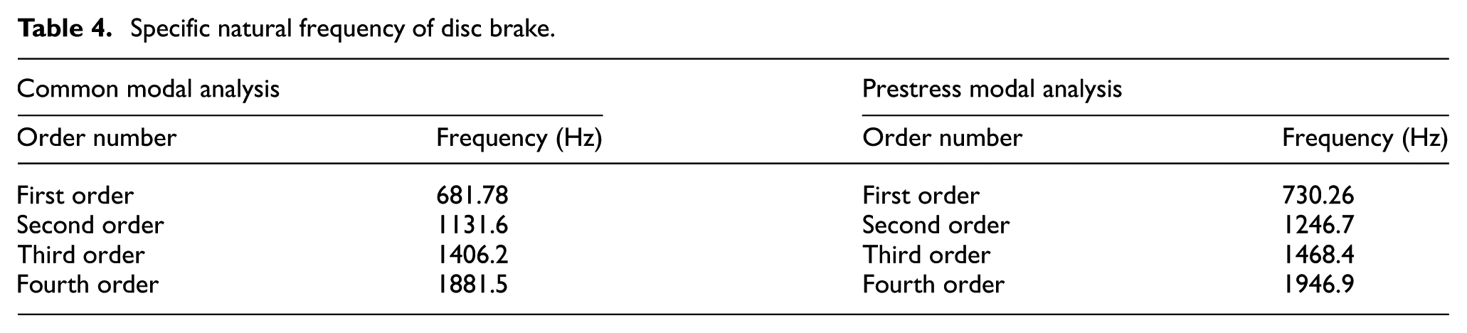
According to the natural frequency given in Table 4, the natural frequency of the two working states of the disc brake is initially above 600 Hz. According to the vibration pattern of Figure 12, the brake shows the bending deformation trend in the low-mode vibration pattern, and it is concentrated on the brake body. In the high-order mode vibration pattern, the brake master is in the high order mode. It should be shown that the trend of torsional deformation is concentrated on the lining of the cylinder with parts. In the field, the vibration frequency of the hoist is detected by the fast-Fourier transform (FFT) spectrum analysis method between 26.54 and 169.24 Hz, and the first-order natural frequency of the brake is 730.26 Hz and has a higher safety degree in the modal analysis of the prestress.

Vibration pattern of normal mode analysis of prestress modal analysis.
Experimental verification
Checking experiment of sensors’ static characteristics
1. The disc spring force sensor completed by trial is shown in Figure 13(b). The laboratory uses the experimental device shown in Figure 13(a) to calibrate its static characteristics. The main principle is to test the linearity and sensitivity of disc spring force sensor by using the standard spoke sensor and the designed disc spring force sensor for many times.
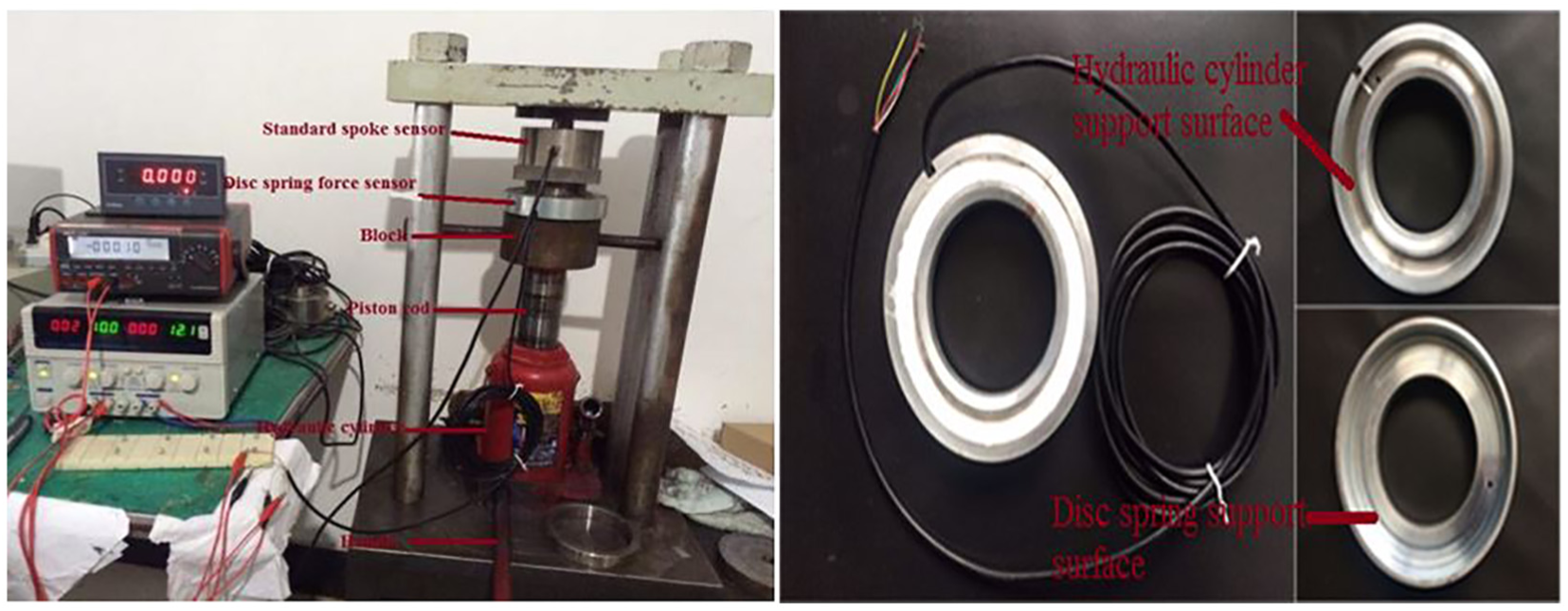
Performance testing equipment: (a) sensor performance testing device and (b) disc spring force sensor in kind.
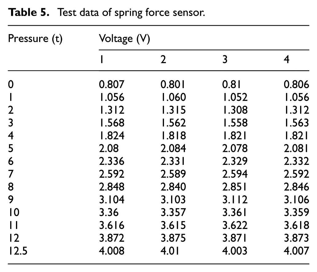
In the experiment, the standard spoke sensor, the disc spring force sensor, and the circular cushion block are placed between the bracket and the hydraulic cylinder, concentric with the piston rod. The power is continuously added to the sensor by the handle. As the two sensors are concentric, the force size is the same. The pressure value is recorded by 1 t, and the value of the pressure and voltage is recorded each time by observing the screen on the left side in Figure 13(a). In order to test the linearity and sensitivity of the sensor, the other variables are constant. The experiment is repeated thrice and the average value is obtained. The test data are shown in Table 5.
Test data of spring force sensor.
According to the average value, it is processed by least square method. Finally, the characteristic curve of the sensor is fitted as shown in Figure 14.
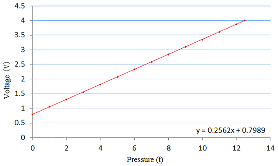
The characteristic fitting curve of the disc spring force sensor.
The linear degree of the spring force sensor of the disc spring is 0.15% and the sensitivity is 0.267 V/t. The linearity and sensitivity of the sensor are in good range, which conforms to the test demands.
2. The positive brake pressure sensor completed by trial is shown in Figure 15.
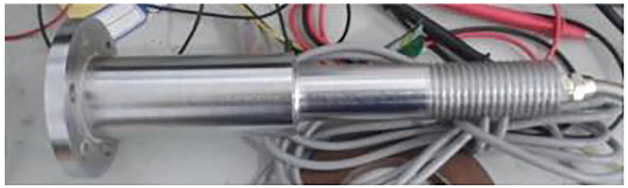
The physical map of the positive brake pressure sensor.
The above-mentioned method is used to check the static characteristics of the positive brake pressure sensor, and the average value of the three sets of data is recorded and fitted. The test data are shown in Table 6.
Test data of the positive brake pressure sensor.

The average value is also processed by the least square method. Finally, the characteristic curve of the sensor is fitted as shown in Figure 16.

Characteristic fitting curve of positive brake pressure sensor.
The linear degree of the spring force sensor is 0.297% and the sensitivity is 0.402 V/t. The experiment shows that the linearity of the sensor is good and meets the test demands. When the two sensors are manufactured, ANSYS software is used to analyze the force of the sensor and find out the area with obvious stress–strain distribution relative to other areas, so as to meet the requirement that the deformation of the fitting position is higher than that of other places under the same external force. A total of 16 strain gauges are evenly attached to the stress-sensitive area, and then, two-thousandths of the standard sensors are used for testing to ensure that the accuracy of the sensors is up to five-thousandths. In the actual working process, 16 brakes are monitored at the same time, and the measured values of each sensor are compared with the average values. If the values exceed 10%, the fault will be diagnosed.
Test experiment of brake
1. Installation of sensor for monitoring gap
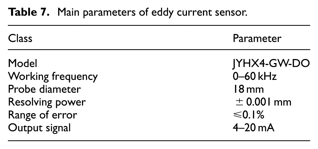
The sensor for monitoring gap is selected with eddy current sensor JYHX4-GW-DO. The displacement sensor of this type can measure the distance between the probes to the detected surface statically and dynamically. The linearity and resolution are high, and the main technical parameters are shown in Table 7.
Main parameters of eddy current sensor.
The sensor is installed on the sluice and lining plate of the barrel by special support. The former is used to monitor the deflection of the drum to determine whether it is within the specified range. The latter is used to monitor the clearance value of the sluice, and the absolute value of the number difference between the closing display value and the opening display value is used as the interlock gap value. The site installation diagram is shown in Figure 17.
2. Installation of disc spring force sensor and positive brake pressure sensor.

Field installation of eddy current sensors: (a) monitoring the deflection of the drum and (b) monitoring gap.
The assembled parts that finished according to the standard are assembled with the original parts to form a brake with monitoring function. The disc spring force sensor replaced the disc spring force of the original disc spring seat, which is used to monitor the opening and closing of brake in real time. The positive brake pressure sensor is installed on the reformed cylinder liner through screws to monitor the braking pressure, and the braking status of the brake is judged by the data comparison of the two sensors. The brake is completed and assembled by the relevant technicians on-site, as shown in Figure 18.
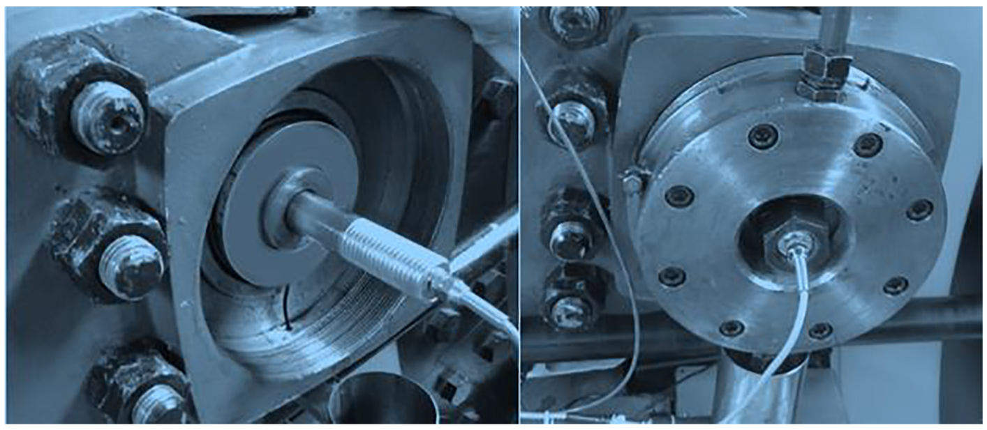
Field installation of pressure sensors: (a) installation of the positive brake pressure sensor and (b) installation of the brake.
Analysis of experimental results
The results in normal condition
The brake is adjusted: the clearance of the brake shoe is adjusted to 2 mm; the gap between the brake shoe clearance of the two sides of brake is controlled in 0.1 mm, and then, the data collection is carried out by the signal acquisition device. The upper computer records the displacement, spring force, and positive brake pressure of the eddy current sensor; the disc spring force sensor; and the positive braking pressure sensor during the opening and closing of the brake, and the related data recorded are given in Table 8.
Part of the experimental data.

From Table 8 it can be observed that, when the brake shoe displacement is zero, disc spring force and positive brake pressure are basically consistent. The maximum error is 3%. When the brake shoe displacement starts increasing, disc spring force also increases. However, the positive brake pressure decreases. Because of the complex working environment, the value is not zero. The next stage is the opposite of the last phase. When the brake shoe displacement is zero again, the situation is similar to the previous phase. The above data are consistent with the desired data.
Meanwhile, the monitoring data are displayed by the developed visual interface of LabVIEW on the computer. The changes in the monitoring data curve during the complete opening and closing of the brake are intercepted. In order to facilitate the analysis, the oil pressure values monitored by the oil pressure sensors are intercepted. The final field experiment data curve is shown in Figure 19.

Curve diagram of experimental data.
As shown in Figure 19, with the rapid rise of oil pressure in the brake, the brake shoe tile and the brake disc are separated from the brake disc. The gap increases rapidly from zero. At this time, the force of the disc spring increases with the rise of the oil pressure, and the brake pressure is rapidly reduced to zero as the brake shoe leaves the brake disc. When the sluice is stable, the oil pressure value, brake clearance, disc spring force, and positive brake pressure all remain constant. During the closing process of brake, with the rapid decline in oil pressure, the brake shoe is rapidly attached to the brake disc under the action of disc spring force, and the brake shoe clearance is reduced to zero at this time. When the closing is completed, the disc spring force is almost equal to the positive brake pressure and remains constant. The experimental results are basically consistent with the theory, which shows that the brake strength meets the requirements of the use and can complete the function of braking and monitoring the positive pressure of braking.
By observing the data curves of Table 8 and Figure 19, it can be found that the positive brake pressure monitored by the sensor is not completely equal when the brake is closed. This is because of the residual pressure in the hydraulic cylinder and the nonstandard disc spring stiffness.
The results in fault condition
As shown in Figure 20, the brake cylinder of Xinyang and Shijiazhuang mines has jammed. The reason for the failure is that the key groove of the guide key is blocked by oil pollution caused by the seepage of hydraulic oil and dust in the environment, and the brake shoe cannot normally fit the brake disc during the braking process. When the distance between brake shoe and brake disc is very small, jamming occurs. At this time, the disc spring force is equal to the positive braking pressure. If the positive braking pressure is normal only according to the disc spring force, the actual positive braking pressure is zero. Actual brake cannot brake normally, but it cannot be accurately judged by disc spring force sensor only. Positive pressure, this miscarriage of justice, is bound to cause major accidents.

Faulty brake in kind.
Therefore, the disc spring force sensor and positive brake pressure sensor discussed in this study are used to verify the above faults. The data obtained during the experiment are shown in Figure 21. From Figure 21, it can be seen that the brake clearance is 0.02 mm, the disc spring force is 4.24 t, the oil pressure is 0.21 MPa, and the positive braking pressure is zero. It is diagnosed that the brake has insufficient braking force.

Curve diagram of experimental data.
Conclusion
A new type of disc brake structure with diagnosing brake fault and real-time monitoring braking pressure is presented in this article, and its structure and working principle are analyzed and expounded; its fault diagnosis process is established. In this article, the overall structure of the brake and the performance of the key components are studied. Based on the 3D modeling software SolidWorks, the simplified model of the virtual prototype of the entire brake and its key components is established. Using the finite element analysis software ANSYS Workbench, the modal analysis and static analysis are carried out to obtain the natural frequency and vibration mode and the structural strength of the key components, which provides a reliable theoretical basis for the experiment. The prototype of disc brake with monitoring function has been tried successfully, and the static characteristic analysis of the disc spring force sensor and the brake pressure sensor is completed in the laboratory. The test experiment on the brake is carried out in the field. The experimental results show that the disc brake can effectively monitor the positive brake pressure in real time; the strength and stiffness meet the requirements of use and verified the correctness and effectiveness of the proposed structural scheme.
Footnotes
Handling Editor: James Baldwin
Declaration of conflicting interests
The author(s) declared no potential conflicts of interest with respect to the research, authorship, and/or publication of this article.
Funding
The author(s) disclosed receipt of the following financial support for the research, authorship, and/or publication of this article: The supports of Production, Prospective Joint Research Projects in Jiangsu Province (No. BY2016026-02), and the Priority Academic Program Development (PAPD) of Jiangsu Higher Education Institutions in carrying out this research are gratefully acknowledged.