
Abstract
Dynamic brake characteristics of disc brake during emergency braking of the kilometer deep coal mine hoist were investigated in the present study. The theoretical model of dynamic brake torque of disc brake during emergency braking was given to explore dynamic brake torque properties of disc brake. The three-dimensional thermo-mechanical coupled finite element model of brake disc–brake shoe was established to explore thermo-mechanical characteristics of disc brake during emergency braking. Effects of effective mass, hoisting acceleration and deceleration, and maximum hoisting speed on dynamic brake torques, equivalent von Mises stress, and temperature fields of disc brake during emergency braking were presented. The results show that the evolutions of brake torque, equivalent stress, and temperature of disc brake present fluctuating characteristics. The dynamic brake torque shows the largest change amplitude during emergency braking in the hoisting stage of constant speed. The largest equivalent stress and temperature are both located near the third brake shoe along the rotational direction at each side. An increase in effective mass causes overall decreases in the peak values of brake torque, equivalent stress, and temperature during emergency braking. Increases in hoisting acceleration/deceleration and maximum hoisting speed cause the increases in the maximum equivalent stress and temperature during emergency braking as compared to the slight decrease in the maximum brake torque.
Introduction
Multi-rope friction hoist systems (Figure 1), widely employed in deep and ultra-deep (>1000 m) coal mines with the high hoisting speed and heavy terminal load, are responsible for hoisting the coal, gangues, equipment, and workers. 1 The disc brake is the last key device to assure the safety of friction hoist system.2–4 In cases of serious safety accidents of over speed, rope breakage or over winding of the hoist, the oil in the oil cavity of disc brake returns to oil tank, and the force of butterfly spring quickly pushes the brake shoe to the brake disc to generate brake torque, which timely locks the hoist and thereby realizes the emergency braking of disc brake. Therefore, during emergency braking, the disc brake is required to provide enough brake torque and reach preset brake deceleration in order to brake the friction hoist safely and reliably.

The multi-rope friction hoisting system and its brake system.
During emergency braking in kilometer deep coal mine, the fluctuating brake torque attributed to dynamic rope tensions,4,5 and the thermal stress due to frictional heat, will require larger brake torque than the designed value, or cause insufficient brake torque. That may induce the brake failure of disc brake, and thereby cause malignant accidents of rope slipping and cage crashing. Therefore, it is of great importance to investigate dynamic brake characteristics (brake torque and three-dimensional thermodynamics) during emergency braking of the kilometer deep coal mine hoist.
In recent years, many scholars have performed research studies on the heat transfer, thermodynamics, and tribological properties of brake disc. Saffar and Shojaei 6 studied the effect of rubber component on wear and thermodynamic properties of brake friction materials. Kumar et al. 7 investigated the effects of various metallic fillers in friction materials on hot-spot appearance during braking. Zhu et al. 8 and Gao and Lin 9 established the three-dimensional transient thermal field model of the brake under constant brake torque during emergency braking. Zhu et al. 10 explored frictional catastrophe mechanisms of brake shoe during repetitious emergency braking. Bao et al.11,12 studied effects of brake parameters on friction properties of brake shoe during emergency braking. However, simulating the actual working condition, dynamic brake torque of disc brake, and dynamic thermodynamic properties of disc brake with dynamic torque during emergency braking of kilometer deep coal mine hoist have not been reported yet.
Therefore, the objective of the present study is to investigate dynamic brake characteristics of disc brake during emergency braking of the kilometer deep coal mine hoist. Section “Dynamic brake torque theory during emergency braking” presents the theoretical model of dynamic brake torque of disc brake during emergency braking. In section “Dynamic brake torque of disc brake during emergency braking,” effects of effective mass, hoisting acceleration/deceleration, and maximum hoisting speed on the dynamic brake torque of disc brake during emergency braking were explored. The thermo-mechanical coupled finite element model of brake disc–brake shoe was established in section “Thermo-mechanical coupled finite element model of brake disc–brake shoe.” Section “Thermo-mechanical coupled finite element analyses of brake disc–brake shoe during emergency braking” exhibits effects of effective mass, hoisting acceleration/deceleration, and maximum hoisting speed on the equivalent von Mises stress and temperature of brake disc and brake shoe during emergency braking.
Dynamic brake torque theory during emergency braking
Figure 1 shows the simplified hoisting system. Based on the moment balance principle, we can obtain equation (1) 5

where T is the brake torque, R is the radius of friction pulley, M is the inertia moment of hoisting system, and S1 and S2 are dynamic rope tensions of hoisting rope at both tangents of friction pulley, respectively. In the equation,
Assuming the constant brake deceleration during emergency braking, dynamic tensions of hoisting rope at friction pulley tangents at lifting and lowering sides, S1 and S2, are written by 13


where g is the acceleration of gravity, that is, 9.8 m/s2; a is the brake deceleration, that is, 3.8 m/s2; t is the brake time during emergency braking, s; l is the vertical length of hoisting rope during emergency braking, m; α is the ratio of hoisting rope mass to effective mass; C is the propagation velocity of elastic wave in the vertical hoisting rope, m/s; E is the elastic modulus of hoisting rope, MPa; A is the cross section of hoisting rope, mm2; ρ is the mass of hoisting rope per meter, kg/m; and F1 and F2 are static tensions of hoisting rope at friction pulley tangents at lifting and lowering sides, respectively. The time t is set zero as the brake deceleration transmits from the top tangent of vertical hoisting rope to the container. During emergency braking, the vertical lengths of hoisting rope at both sides are assumed to be constant attributed to the slight effect of vertical hoisting rope length change on dynamic rope tensions, S1 and S2. The effective mass is the sum of masses of container, effective load, and tail rope.
Therefore, we can obtain dynamic tensions of hoisting rope at lifting and lowering sides during emergency braking employing equations (2)–(7). Dynamic brake torque during emergency braking can be derived through substitutions of dynamic tensions into equation (1). Emergency braking at different hoisting stages (acceleration, constant speed, and deceleration) and with different hoisting parameters (effective mass, maximum hoisting speed, acceleration, and deceleration) induces distinct dynamic tensions and thereby different dynamic brake torques.
Dynamic brake torque of disc brake during emergency braking
A typical case
According to hoisting parameters of multi-rope friction hoisting system in Guqiao coal mine in China (Table 1) and the speed curve of hoisting container (Figure 2), dynamic tensions of hoisting rope at lifting and lowering sides during emergency braking, that is, S1 and S2, are obtained employing equations (2)–(7). For simplicity, we chose a time midpoint in every hoisting stage, that is, A point (t = 8.67 s) in acceleration stage, B point (t = 47.13 s) in constant speed stage, and C point (t = 85.60 s) in deceleration stage. Therefore, evolutions of tension differences, S1−S2, corresponding to A, B, and C points can be calculated as shown in Figure 3. Substitutions of tension differences, S1−S2, into equation (1) can derive the brake torque during emergency braking at distinct hoisting stages as shown in Figure 4. It is clearly seen from Figures 3 and 4 that the brake time during emergency braking presents the largest value at the constant hoisting stage attributed to the largest hoisting speed as compared to hoisting stages of acceleration and deceleration. Evolutions of tension differences and brake torques present similar fluctuating characteristics. In both cases, the fluctuation frequency, affected by the fluctuation frequency of S1−S2, is the smallest during emergency braking in the stage of constant speed. The fluctuation frequency of S1−S2 depends on the larger value of frequencies of S1 and S2. The fluctuation frequency, ω, of dynamic tension can be determined by
Hoisting parameters of the coal mine hoist system.

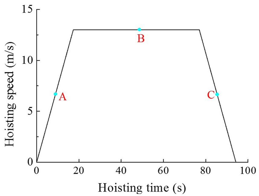
Hoisting speed curve.

Difference between dynamic rope tensions at both sides.

Brake torque during emergency braking at different hoisting stages.
Effect of effective mass
Figure 5 shows the brake torque of disc brake during emergency braking at hoisting stages of acceleration (t = 8.67 s), constant speed (t = 47.13 s), and deceleration (t = 85.60 s) with effective masses of 16,000, 24,000, and 31,000 kg, respectively. In Figure 5(a)–(c), at the initial braking stage, the brake torque decreases with increasing effective mass. The increased rope tension at the lifting side with increasing effective mass, and the unchanged effective mass at the lowering side, induces an increase in the rope tension difference, S1−S2. Therefore, more inertia moment of hoisting system is overcome by the large dynamic rope tension difference at the initial braking stage, and thus causes the decrease in the required brake torque.

Evolutions of the brake torque during emergency braking of disc brake in cases of different effective masses: (a) acceleration, (b) constant speed, and (c) deceleration.
An increase in effective mass causes the same fluctuation frequency (Figure 5(a)), slight difference in fluctuation frequency (Figure 5(b)), and a decrease in fluctuation frequency (Figure 5(c)). As we know in section “A typical case,” the larger effective mass or vertical rope length causes decreased fluctuation frequency of dynamic rope tension S1 or S2; the fluctuation frequency of brake torque during emergency braking depends on the larger value of fluctuation frequencies of dynamic tension of hoisting rope at lifting and lowering sides. At t = 8.67 s, the fluctuation frequency of brake torque during emergency braking depends on the fluctuation frequency of dynamic tension of hoisting rope at the lowering side attributed to smaller vertical rope length and effective mass. Therefore, Figure 5(a) shows the same fluctuation frequency of brake torque. At t = 47.13 s, distinct effective mass causes slightly different fluctuation frequency of brake torque during emergency braking. At t = 85.60 s, the fluctuation frequency of brake torque depends on the fluctuation frequency of dynamic tension of hoisting rope at the lifting side due to smaller vertical rope length. Therefore, the larger effective mass decreases the fluctuation frequency of dynamic tension of hoisting rope at the lifting side, and thus decreases the fluctuation frequency of brake torque during emergency braking. Variation ranges of brake torque during emergency braking at distinct hoisting stages with different effective mass are shown in Table 2. Table 2 shows that an increase in effective mass causes decreases in peak and valley brake torques during emergency braking at distinct hoisting stages.
Ranges of the brake torque during emergency braking of disc brake in cases of different effective masses.

Effects of hoisting acceleration and deceleration
In order to investigate effects of hoisting acceleration and deceleration on dynamic brake torque properties, we apply the emergency braking with the same hoisting velocity at hoisting stages of acceleration and deceleration, and with the same lifting height (500 m) at the hoisting stage of constant speed. It is clearly seen from Figure 6 that at hoisting stages of acceleration and deceleration, the initial brake toque during emergency at hoisting acceleration/deceleration of 0.75 m/s2 is slightly larger as compared to the case of hoisting acceleration/deceleration of 0.5 m/s2; at the hoisting stage of constant speed, both evolution curves of brake torque during emergency braking at hoisting accelerations/decelerations of 0.5 and 0.75 m/s2 coincide well. That is because during emergency braking at hoisting stages of acceleration and deceleration, the vertical rope length at the lifting side is larger in the case of hoisting acceleration of 0.75 m/s2. According to equations (1)–(7) in section “Dynamic brake torque theory during emergency braking,” distinct dynamic rope tensions induce the difference in the brake torque during emergency braking. During emergency braking at the hoisting stage of constant speed, the same lifting height and vertical rope length induce the same dynamic rope tension and thus the same evolution of brake torque during emergency braking according to equation (1).

Evolutions of the brake torque during emergency braking of disc brake in cases of different hoisting accelerations and decelerations: (a) acceleration, (b) constant speed, and (c) deceleration.
According to sections “A typical case” and “Effect of effective mass,” the fluctuation frequency of brake torque during emergency braking in the case of hoisting stage of acceleration depends on the fluctuation frequency of dynamic rope tension at the lowering side. Larger hoisting acceleration causes smaller vertical rope length at the lowering side when reaching the same hoisting speed; according to the equation of fluctuation frequency, ω, larger fluctuation of dynamic rope tension in the lowering side causes the larger fluctuation frequency of brake torque during emergency braking in the case of hoisting acceleration of 0.75 m/s2. The fluctuation frequency of brake torque during emergency braking in the case of hoisting stage of deceleration depends on the fluctuation frequency of dynamic rope tension at the lifting side. Larger hoisting deceleration causes smaller vertical rope length at the lifting side, which induces larger fluctuation frequency of dynamic rope tension and thereby leads to larger fluctuation frequency of brake torque during emergency braking in the case of hoisting acceleration of 0.75 m/s2. Fluctuation ranges of brake torque during emergency braking at three hoisting stages are listed in Table 3.
Ranges of the brake torque during emergency braking of disc brake.

Effects of maximum hoisting speed
Figure 7 shows evolutions of brake torque during emergency braking at hoisting stages of acceleration, constant speed, and deceleration (corresponding to Points A, B, and C) in cases of maximum hoisting speeds of 8, 10, and 13 m/s, respectively. In cases of hoisting stages of acceleration and deceleration, an increase in maximum hoisting speed induces larger and smaller peak brake torques during emergency braking at points A and C (Figure 7(a) and (c)), respectively. In the case of hoisting stage of constant speed, evolution curves of brake torque during emergency braking at different maximum hoisting speeds coincide well (Figure 7(b)). However, different maximum hoisting speeds induce different brake time and thereby cause distinct terminal time of three evolution curves.

Evolutions of brake torque during emergency braking of disc brake in cases of different maximum hoisting speeds: (a) acceleration, (b) constant speed, and (c) deceleration.
In the case of hoisting stage of acceleration (deceleration), the fluctuation frequency of brake torque during emergency braking decreases with increasing maximum hoisting speed attributed to the increase in vertical rope length as shown in Figure 7(a) (Figure 7(c)). Fluctuation ranges of brake torque during emergency braking at three hoisting stages are listed in Table 4.
Ranges of brake torque during emergency braking of disc brake in cases of different maximum hoisting speeds.

In conclusion, as the effective mass increases from 16,000 to 31,000 kg, the range of brake torque during emergency braking presents an overall expansion from 1.18 × 10⁶–7.58 × 10⁶ to 7.55 × 10⁵–7.27 × 10⁶ N·m (Table 2). As the hoisting acceleration and deceleration increases from 0.5 to 0.75 m/s2, the range of brake torque during emergency braking narrows from 7.55×10⁵–7.41 × 10⁶ to 7.55 × 10⁵–7.27 × 10⁶ N·m (Table 3). As the maximum hoisting speed increases from 8 to 13 m/s, the range of brake torque during emergency braking narrows from 7.55 × 10⁵–7.41 × 10⁶ to 7.55 × 10⁵–7.27 × 10⁶ N·m (Table 4). It is clearly seen that as compared to influences of hoisting acceleration and deceleration and maximum hoisting speed, the change of effective mass causes a larger degree of influence on the range of brake torque during emergency braking, which is beneficial for the ultra-deep coal mine hoist design.
Thermo-mechanical coupled finite element model of brake disc–brake shoe
Generation of the structure
In order to simulate the actual working condition, we employ the full-scale disc brake with actual dimensions. The brake disc has the inner diameter of 2200 mm, outer diameter of 2800 mm, thickness of 70 mm, and average friction radius of 2500 mm. The brake shoe has the length of 290 mm, width of 172 mm, and thickness of 25 mm. The three-dimensional contact structure of brake disc–brake shoe was established employing SolidWorks software. Afterward, the brake disc and brake shoe were imported into ABAQUS 6.10/CAE and assembled together. Therefore, the three-dimensional finite element model of brake disc–brake shoe was established.
Material properties and structural discretization
In the three-dimensional contact model, the brake disc and brake shoe are both made of homogeneous and isotropic materials. The brake disc and brake shoe are made of 65Mn and resin-based non-asbestos brake shoe material, respectively. Other material properties of brake disc and brake shoe can be found in Table 5 according to Ding. 14
Material properties of brake disc and brake shoe.

Three-dimensional solid linear brick elements (C3D8RT) were employed for the structural discretization. The brake disc and brake shoe were meshed using 21,240 and 500 elements, respectively, and using 27,258 and 726 nodes, respectively. Each node has 3 degrees of freedom, that is, translations in X, Y, and Z directions. There are six pairs of brake shoes, and each side exhibits three pairs. Each pair of brake shoes contacts front and back surfaces of the brake disc. Brake shoes contacting front surfaces of the brake disc are numbered 1–6, respectively, while brake shoes contacting front surfaces of the brake disc are numbered 1′–6′, respectively. The three-dimensional finite element model after meshing is shown in Figure 8. Cartesian coordinate system is located in the center of brake disc.

Three-dimensional finite element model.
Interaction properties
The thermo-mechanical coupling module of ABAQUS is employed for the dynamic analyses. Contact surface interactions were defined between contacting components (brake disc–brake shoe) via the contact pair approach in ABAQUS. The master–slave algorithm and finite sliding algorithm were employed to deal with local contacts between contacting components. Hard contact (contact separation not allowed) and normal contact properties were applied between brake disc and brake shoe; the penalty algorithm was employed to deal with the contact between brake disc and brake shoe. In order to determine the coefficient of friction between brake disc and brake shoe, the tribo-brake test rig (Figure 9(a)) can be employed to carry out emergency braking tests. The loading procedure during emergency braking can be found in Figure 9(b). Evolutions of the coefficient of friction between brake disc and self-made resin-based non-asbestos brake shoe material brake shoe during emergency braking 15 can be found in Figure 10. Figure 10(a) shows evolutions of coefficient of friction between brake disc and brake shoe, and surface temperature rise of brake disc during emergency braking. It is clearly seen that the evolution of coefficient of friction presents stages of abrupt rise, slight decrease, stabilization, and abrupt decline. The evolution of brake disc surface temperature exhibits the rise at first and then a decrease. The coefficient of friction between brake disc and brake shoe generally exhibits a reverse change trend with brake disc surface temperature; however, the coefficient of friction changes slightly. Figure 10(b) shows that an increase in initial braking speed causes the slight variation of coefficient of friction at the stabilized stage. Figure 10(a) and (b) shows that the average coefficients of friction at the stabilized stages are approximately 0.4 in all cases. Therefore, in the present study, we assume the constant coefficient of friction for simplicity, that is, μ = 0.4.

Tribo-brake test rig of brake disc and brake shoe and loading procedure: (a) tribo-brake test rig of brake disc and brake shoe and (b) loading procedure during emergency braking.

Evolutions of the coefficient of friction between brake disc and brake shoe during emergency braking 15 : (a) 12 m/s, 2.00 MPa and (b) 2.00 MPa.
During emergency braking, we ignore the wear of brake disc and brake shoe, and mainly focus on the heat conduction and heat convection. Moreover, the following assumptions were made:14,16
the ambient temperature of 25°C;
convective heat transfer coefficient of 5.3;
braking without slippage;
unchanging coefficients of friction;
stable and homogeneous contact pressure between brake disc and brake shoe;
constant braking deceleration;
90% dissipated energy caused by friction converted to heat;
no external factors (such as road inconsistencies, air resistance).
Constraints and boundary conditions
The reference point was established at a distance away from the back surface of brake disc to couple the nodes on the back surface. The distributing coupling mode was employed in order to achieve the same motion between the reference point and corresponding coupled nodes. The speed, rotating direction, and acceleration of the brake disc are controlled by the movement of the reference point. The reference point has only the rotational degree of freedom along U3 direction, while nodes of brake shoe have the translational degree of freedom along U3 direction to apply the brake pressure during emergency braking. Other degrees of freedom of the brake disc and brake shoe are constrained.
The brake pressure between the brake disc and brake shoe can be described as equation (8). 17 The substitution of dynamic brake torques during emergency braking in section “Dynamic brake torque of disc brake during emergency braking” into equation (8) derives dynamic brake specific pressure between contacting components. Therefore, the dynamic brake pressure with time is applied to the brake shoe surface in order to obtain the dynamic brake torque and thereby to realize the emergency braking with constant deceleration

where P is the brake pressure, Pa; T is the brake torque, N·m; N is the number of brake shoe; A is the effective friction area of each brake shoe; μ is the coefficient of friction; and Rm is the average friction radius. In the present study, N = 12, Ae = 0.05 m2, μ = 0.4, and Rm = 2.5 m.
For simplicity, we mainly focus on thermo-mechanical coupling characteristics of brake disc during emergency braking in the case of hoisting stage of constant speed. The initial brake speeds are 8, 10, and 13 m/s, respectively. According to Table 1, the constant brake deceleration during emergency braking is assumed to be 3.8 m/s2. Therefore, the brake velocity and brake angular velocity can be written as V = V0− 3.8t and ω = ω0− 1.52t, respectively.
Thermo-mechanical coupled finite element analyses of brake disc–brake shoe during emergency braking
Stress and temperature fields of brake disc and brake shoe in a typical case
Equivalent stress and temperature distributions on the brake disc and brake shoe
In order to explore stress and temperature distributions of brake disc and brake shoe, the thermo-mechanical coupled finite element analyses of brake disc–brake shoe during emergency braking in the case of hoisting stage of constant speed with the effective mass of 31,000 kg, hoisting acceleration/deceleration of 0.75 m/s2, and maximum hoisting speed of 13 m/s. Figure 11 shows stress and temperature distributions of brake disc and brake shoe during emergency braking at 2.812 s. It is obviously observed from Figure 11 that during emergency braking with the counterclockwise rotation of brake disc, the maximum stress and temperature of contacting components are 22.77 MPa and 49.57°C, respectively, which are both located near the average friction radius of brake disc. The stress distribution is larger near the average friction radius of brake disc as compared to inner and outer sides. At the friction brake region, the stress and temperature both increases gradually along the rotating direction of brake disc, and both reach the maximum values at contacting regions between the brake shoes, that is, 3 and 6, and the brake disc. As the rotating brake disc passes through each brake shoe, the kinetic energy is transformed into friction heat; the contact region between the brake disc and brake shoe exhibits higher contact stress and worse thermal convection effect. Friction heat gradually superimposes from the friction inlet to the friction outlet of each brake shoe. As the regions contacting brake shoes 1 and 4 coming out of the friction outlets, and entering the friction inlets of brake shoes 2 and 5, there is still a lot of heat not dissipated attributed to the poor thermal convection effect between brake disc and air and the close distance between adjacent brake shoes. Therefore, those regions on the brake disc contacting brake shoes 2 and 5 cause friction heat again, and thereby induces the superposition of temperature and thermal stress on the friction contact region of brake disc along the rotating direction. However, long distances between brake shoes 3 and 4, and between brake shoes 6 and 1, cause sufficient exchange of friction heat between the brake disc and air, which induces the decreases in the stress and temperature at these regions.

Equivalent stress and temperature distributions of disc brake during emergency braking at 2.812 s: (a) equivalent stress and (b) temperature field.
Evolutions of equivalent stress and temperature on the brake disc and brake shoe
In order to quantitatively reveal the evolutions of stress and temperature on contacting surfaces of brake disc and brake shoe during emergency braking, the nodes along radial directions of contacting surfaces of brake disc and brake shoe 6 are selected as shown in Figure 12. As indicated in Heng, 18 temperature values at nodes on contacting surfaces of brake disc and brake shoe present the largest as compared to nodes inside the brake disc and brake shoe. Therefore, we mainly focus on evolutions of stress and temperature on contacting surfaces of brake disc and brake shoe during emergency braking in the present study. However, the stress and temperature distributions of nodes inside the brake disc and brake shoe are of great significance to indicating heat exchange and conduction properties of brake disc and brake shoe, which will be investigated in future studies.

Distribution of selected nodes on the surface of brake disc and brake shoe: (a) brake disc and (b) brake shoe.
Figure 13 shows evolution curves of equivalent Von Mises stress and temperature on brake disc and brake shoe surfaces. It is clearly seen from Figure 13(c) and (d) that on the contact surface of brake disc, the equivalent stress and temperature at the average radius location, point C, both present the maximum values, decreases gradually toward both sides of the radial direction. However, points A and E outside the contact area present unobvious increases in the equivalent stress and temperature. Temperature evolution curves of points B, C, and D all show the multi-step change trend of an increase at first and then a slight decrease; the rise speed and amplitude of the temperature at the initial stage are larger than those at the later stage. That is because high speed of brake disc at the initial stage of braking causes large friction heat generation, and a decrease in brake disc speed during emergency braking leads to the increase in the heat dissipation. Therefore, the coupled effects of time-varying heat generation, heat dissipation, and dynamic brake torque cause the overall upward trend and multi-step change of temperature evolution curve. Evolution curves of the equivalent stress of distinct nodes all present similar variation trends of temperature evolution curves. The node equivalent stress exhibits the decreasing trend from the average friction radius toward the radially outward direction, which is attributed to the high thermal stress at the location with high temperature rise. Figure 13(a) and (b) shows that evolution curves of equivalent stress and temperature of various nodes all exhibit the increase–decrease–increase trend, and the friction radius location presents high equivalent stress and high temperature field due to the coupled roles of time-varying heat generation, heat dissipation, and thermal stress. The temperature fields of various nodes of brake shoe are not the highest at the end of braking attributed to the coupled effects of a decrease in heat generation, heat exchange, and time-varying brake torque.

Equivalent stress and temperature distribution on the surfaces of brake disc and brake shoe during emergency braking: (a) equivalent stress distribution of brake shoe, (b) temperature distribution of brake shoe, (c) equivalent stress distribution of brake disc, and (d) temperature distribution of brake disc.
Effects of hoisting parameters on stress and temperature fields of brake disc and brake shoe
According to section “Stress and temperature fields of brake disc and brake shoe in a typical case,” the brake shoe 6 presents the largest equivalent stress and temperature during emergency braking. Therefore, the central node at the average friction radius of brake shoe is chosen as the reference point as shown in Figure 14(b). The locations of maximum stress and temperature at distinct braking conditions are not fixed at certain node in the case of brake disc. Therefore, for simplicity, the location of maximum equivalent stress on the brake disc during each emergency braking is chosen as the reference point as shown in Figure 14(a). For example, during emergency braking at the acceleration hoisting stage with the hoisting acceleration/deceleration of 0.75 m/s2, effective mass of 31,000 kg, and maximum hoisting speed of 13 m/s, the node 4467 with the maximum equivalent stress on the brake disc is chosen as the reference node.

Distribution diagram of node on the surface of brake disc and brake shoe: (a) brake disc and (b) brake shoe.
Effect of effective mass
Dynamic brake torques at distinct effective masses are substituted into equation (8) to obtain the dynamic brake specific pressure. Figures 15–17 show that during emergency braking at hoisting stages of acceleration, constant speed, and deceleration, an increase in effective mass induces overall decreases in the peak equivalent stress and temperature, which coincides well with the conclusion that an increase in effective mass causes a decrease in the peak brake torque as depicted in section “Effect of effective mass.”

Evolutions of the equivalent stress and temperature of brake disc–brake shoe during emergency braking at the hoisting stage of acceleration with different effective masses: (a) equivalent stress distribution of brake shoe, (b) temperature distribution of brake shoe, (c) equivalent stress distribution of brake disc, and (d) temperature distribution of brake disc.

Evolutions of the equivalent stress and temperature of brake disc–brake shoe during emergency braking at the hoisting stage of constant speed with different effective masses: (a) equivalent stress distribution of brake shoe, (b) temperature distribution of brake shoe, (c) equivalent stress distribution of brake disc, and (d) temperature distribution of brake disc.
Evolutions of the equivalent stress and temperature of brake disc–brake shoe during emergency braking at the hoisting stage of deceleration with different effective masses: (a) equivalent stress distribution of brake shoe, (b) temperature distribution of brake shoe, (c) equivalent stress distribution of brake disc, and (d) temperature distribution of brake disc.
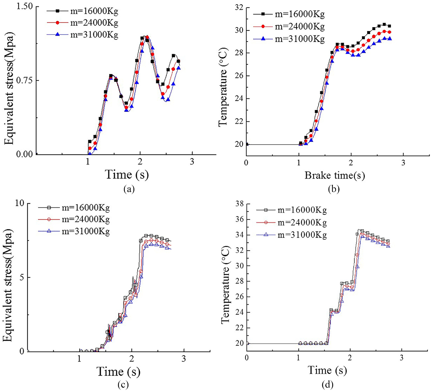
Figures 15(a), 16(a), and 17(a) show that the equivalent stress of brake shoe surface presents a fluctuation with increasing time during emergency braking in cases of distinct effective masses, and an increase in effective mass induces the overall decrease in the equivalent stress, which coincides well with brake toque results during emergency braking in section “Effect of effective mass.”Figures 15(b), 16(b), and 17(b) show the stepped increase in the temperature of brake shoe surface during emergency braking in cases of distinct hoisting stages and effective masses; the equivalent stress presents the overall decrease trend with increasing effective mass. In Figures 15(c) and (d), 16(c) and (d), and 17(c) and (d), evolutions of the equivalent stress and temperature of brake disc surface all present the stepped upward change trends with increasing time; an increase in effective mass causes overall decreases in the equivalent stress and temperature of brake disc surface during emergency braking in cases of distinct hoisting stages. As compared to cases of effective masses of 24,000 and 31,000 kg, the equivalent stress and temperature of brake shoe surface during emergency braking in the case of effective mass of 16,000 kg present larger values attributed to the larger fluctuation frequency of brake torque. During emergency braking at the hoisting stage of constant speed, the equivalent stress and temperature of brake disc and brake shoe surfaces all present the largest values maybe attributed to larger initial brake speed and longer brake time. The maximum equivalent stress and temperature of brake disc and brake shoe surfaces during emergency braking in cases of distinct effective masses are listed in Table 6.
Maximum equivalent stress and temperature of disc brake during emergency braking in cases of different effective mass.

Effect of hoisting acceleration/deceleration
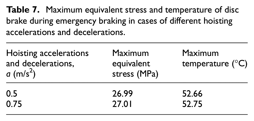
Figures 18–20 show that during emergency braking at the hoisting stage of acceleration, the equivalent stress and temperature of brake disc and brake shoe all increase with increasing hoisting acceleration. During emergency braking at the hoisting stage of constant speed, an increase in hoisting acceleration causes unobvious changes in the equivalent stress and temperature of brake disc and brake shoe; the evolution curves all coincide. During emergency braking at the hoisting stage of deceleration, an increase in hoisting deceleration induces overall decreases in the equivalent stress and temperature of brake shoe; the equivalent stress and temperature of brake disc both increases at first and then decreases with increasing hoisting deceleration. The maximum equivalent stress and temperature of brake disc–brake shoe during emergency braking at different hoisting accelerations/decelerations are shown in Table 7.

Evolutions of the equivalent stress and temperature of brake disc–brake shoe during emergency braking at the hoisting stage of acceleration with different hoisting accelerations and decelerations: (a) equivalent stress distribution of brake shoe, (b) temperature distribution of brake shoe, (c) equivalent stress distribution of brake disc, and (d) temperature distribution of brake disc.

Evolutions of the equivalent stress and temperature of brake disc–brake shoe during emergency braking at the hoisting stage of constant speed with different hoisting accelerations and decelerations: (a) equivalent stress distribution of brake shoe, (b) temperature distribution of brake shoe, (c) equivalent stress distribution of brake disc, and (d) temperature distribution of brake disc.

Evolutions of the equivalent stress and temperature of brake disc–brake shoe during emergency braking at the hoisting stage of deceleration with different hoisting accelerations and decelerations: (a) equivalent stress distribution of brake shoe, (b) temperature distribution of brake shoe, (c) equivalent stress distribution of brake disc, and (d) temperature distribution of brake disc.
Maximum equivalent stress and temperature of disc brake during emergency braking in cases of different hoisting accelerations and decelerations.
Effect of maximum hoisting speed
Figures 21(a), 22(a), and 23(a) show that the equivalent stress presents upward fluctuating change trend in each maximum hoisting speed case, and an increase in maximum hoisting speed causes an overall decrease in the frequency of equivalent stress fluctuation of brake shoe during emergency braking at each hoisting stage. Figures 21(b), 22(b), and 23(b) show that an increase in time causes the gradual increase in the temperature of brake shoe surface during emergency braking; an increase in maximum hoisting speed induces the overall increase in the temperature of brake shoe surface attributed to larger brake time and more friction heat. Figures 21(c), 22(c), and 23(c) show that the equivalent stress of brake disc surface presents the stepped rapid increase with increasing time; an increase in maximum hoisting speed induces the overall increase in the maximum equivalent stress during emergency braking at each hoisting stage; the equivalent stress increases at first and then decreases with increasing maximum hoisting speed. Figures 21(d), 22(d), and 23(d) show that the evolutions of temperature of brake disc surface present the stepped increases with time during emergency braking at hoisting stages with distinct maximum hoisting speeds. An increase in maximum hoisting speed induces the overall increase in the temperature of brake disc during emergency braking at each hoisting stage. The maximum equivalent stress and temperature both occur during emergency braking at the hoisting stage of constant speed; thermal stress parameters in cases of three maximum hoisting speeds are shown in Table 8.

Evolutions of the equivalent stress and temperature of brake disc–brake shoe during emergency braking at the hoisting stage of acceleration with different maximum hoisting speeds: (a) equivalent stress distribution of brake shoe, (b) temperature distribution of brake shoe, (c) equivalent stress distribution of brake disc, and (d) temperature distribution of brake disc.

Evolutions of the equivalent stress and temperature of brake disc–brake shoe during emergency braking at the hoisting stage of constant speed with different maximum hoisting speeds: (a) equivalent stress distribution of brake shoe, (b) temperature distribution of brake shoe, (c) equivalent stress distribution of brake disc, and (d) temperature distribution of brake disc.

Evolutions of the equivalent stress and temperature of brake disc–brake shoe during emergency braking at the hoisting stage of deceleration with different maximum hoisting speeds: (a) equivalent stress distribution of brake shoe, (b) temperature distribution of brake shoe, (c) equivalent stress distribution of brake disc, and (d) temperature distribution of brake disc.
Ranges of the equivalent stress and temperature of disc brake during emergency braking in cases of different maximum hoisting speeds.

It is clearly seen from Tables 6–8 that the maximum temperature disc brake during emergency braking does not exceed 70°C, which coincides with results in Yin, 15 Bao, 17 and Wang et al. 19 As we know, 6 braking pairs (12 brake shoes) are employed in the present study. In the numerical simulation, we simulated the single emergency braking process instead of multiple continuous braking processes. The non-asbestos brake shoe material in this study has the thermal decomposition temperature of 300°C–350°C. If a single emergency braking process causes the high temperature of the disc brake, the hoist structure cannot respond to multiple continuous emergency braking cases. Meanwhile, an increase in friction surface temperature would cause the deterioration of tribological properties of brake shoe materials.15,18 Therefore, the working temperature of brake shoe material and the safety factor should be in the appropriate ranges.
Conclusion
The theoretical model of dynamic brake torque of disc brake during emergency braking is established employing theories of dynamic tensions of hoisting rope at friction pulley tangents at lifting and lowering sides. Effects of effective mass, hoisting acceleration and deceleration, and maximum hoisting speed on dynamic brake torque were explored, respectively. The fluctuating dynamic brake torque shows the largest change amplitude during emergency braking in the hoisting stage of constant speed. An increase in effective mass causes no difference, a slight difference, and a decrease in the fluctuation frequency during emergency braking at hoisting stages of acceleration, constant speed, and deceleration, respectively. Peak and valley brake torques during emergency braking at distinct hoisting stages decrease with increasing effective mass. Increases in hoisting acceleration/deceleration and maximum hoisting speed causes the decreases in ranges of brake torque during emergency braking.
The three-dimensional thermo-mechanical coupled finite element model of brake disc–brake shoe was established. The largest values of fluctuating equivalent von Mises stress and temperature are both located near the third brake shoe along the rotational direction at each side. The equivalent stress and temperature at the average radius location both present the maximum values, and decreases gradually toward both sides of the radial direction. An increase in effective mass induces overall decreases in the peak equivalent stress and temperature of brake disc–brake shoe during emergency braking. Increases in hoisting acceleration/deceleration and maximum hoisting speed cause the increases in the maximum equivalent stress and temperature of brake disc–brake shoe during emergency braking.
Footnotes
Appendix 1
Acknowledgements
The authors wish to thank TAPP and PAPD.
Handling Editor: Michal Kuciej
Declaration of conflicting interests
The author(s) declared no potential conflicts of interest with respect to the research, authorship, and/or publication of this article.
Funding
The author(s) disclosed receipt of the following financial support for the research, authorship, and/or publication of this article: The research reported here was supported by the National Key Research and Development Program (2016YFC0600907).