
Abstract
The drive system of shearer traction unit is affected by complex load interference and system structure, which results in the problem of unbalanced power of dual-motor of shearer traction unit. A new type of dual-motor frequency conversion control system for shearer traction unit with “common rectification and dual inverters” is designed. And a dual-motor power balance control method based on particle swarm optimization torque cross-coupled control is proposed. The new frequency conversion control system adopts a parallel structure of two inverter circuits with a common DC bus. Particle swarm optimization is used to optimize the PID control parameters of torque cross-coupling control, which solves the problem that it is difficult to gain optimal PID parameters. The control model is established using Matlab/Simulink simulation software. The proposed control method and the master-slave control method are compared by simulation. The results show that the control effect of proposed control method is better synchromization and power balance effect than the master-slave control method. The proposed control method is applied to dual-motor control of shearer traction unit for experimental verification. The results indicate that the proposed power balance control method realizes that the output torque ratio of dual-motor is between 0.9 and 1.1.
Introduction
In the process of coal mining, due to complex working conditions, many influencing factors, as well as different geological conditions, coal and rock properties, the load of the shearer traction unit has a strong impact. In addition, the stiffness of shaft is different, the degree of gear lubrication is different. The unknown gear meshing deviation is easy to cause uneven load distribution, which leads to the unbalanced power of the dual-motor in shearer traction unit.1,2 In engineering applications, due to manufacturing errors and parameter drift, even if the model of each motor is the same, its mechanical characteristics are difficult to be completely consistent, which leads to deviations of output power for dual-motor. One of dual-motor works in light load state, and the other motor works in overload state, which leads to the failure of the traction drive system.3,4 Therefore, it is necessary to deeply study the power balance control method of dual-motor in the shearer traction unit.
At present, many scholars have studied the multi-motor power balance control of mechanical system. Li 5 aimed at the problems of power deviation between multiple asynchronous motors connected with hard shafts, a power balance control method based on the combination of multi-DTC and online parameter identification is proposed, which avoids motor burnout due to unbalanced load. Shi et al. 6 proposed an improved deviation coupling structure in view of the large synchronization error of the starting process in multi-motor speed control. Each motor followed the running trajectory of the virtual motor during the starting process, thereby effectively reducing the start-up process synchronization error. Geng et al. 7 designed a synchronous controller for the problem of unbalanced output torque in the case of dual-motor driving rigid gears. The synchronous control coefficients K1 and K2 are used to compensate each motor to achieve balanced control of the output torque. Hwang et al. 8 proposed a master-slave controller disturbance observer based sliding mode controller to ensure synchronous steering. A combination of disturbance observer and sliding mode controller is used to ensure strong robustness to model uncertainty and external disturbances. Wang et al. 9 designed a cross-coupled controller to realize the detection and compensation correction of the dual-motor synchronization position error. Xiao et al. 10 aimed at the problem of unbalanced output power of belt conveyor drive motor, a master-slave control strategy is proposed, which uses a given speed control strategy to control the master motor and a given torque strategy to control the slave motor. The multi-motor power balance of the belt conveyor was realized. Xiao et al. 11 conducted research on high-performance control under dual-motor master-slave structure. A speed sensorless model prediction strategy for coaxial dual-motor master-slave structure based on double sliding mode estimation was proposed. On the basis of optimizing the torque dynamic and steady-state balance performance of dual-motor, speed sensorless control is performed to improve the overall fault-tolerant performance of the system. Bogiatzidis et al. 12 aimed at the situation of two induction motors driving the load together under the direct torque control mode, the sum of speed PI controller and torque PI controller are used as the output torque reference value, which solved the problem of power imbalance caused by mechanical differentiation.
In summary, the traditional master-slave control system of one-to-one frequency conversion for shearer traction unit has the disadvantage that the slave motor cannot timely and stably follow the power change of the main motor due to the delay of the master-slave communication and the weak coupling of the control system. And the traditional torque cross-coupled control method is difficult to obtain the optimal PID parameters for torque variation complex system. In this study, our main contribution is to propose a new type of dual-motor frequency conversion control system for shearer traction unit with “common rectification and dual inverters” and a dual-motor power balance control method based on particle swarm optimization torque cross-coupled control. The dual-motor are driven by proposed frequency conversion system, which can effectively avoid the problem of power imbalance of the one-to-one frequency conversion system and realize high-efficiency and energy-saving control. The particle swarm algorithm is used to optimize the PID parameters of the torque cross-coupling control method for torque variation complex system of shearer traction unit, which solves the problem that the traditional PID control method is difficult to obtain the optimal PID parameters, so as to realize the high power balance accuracy of dual-motor power. The study provides a reference idea for the dual-motor power balance control and is of great significance to the safe, efficient and intelligent mining of coal mines.
Dual-motor control scheme of the new frequency conversion control system
The driving scheme of shearer traction unit is shown in Figure 1. It includes a transmission system, a variable frequency drive system and a traveling mechanism. The dual-motor are driven by a “common rectification and double inverter” variable frequency system In the same power supply system, the voltage, power and efficiency of the motor are consistent. 13 The traction motor drives the shearer to walk on the rack wheel through a reducer. The drive system of shearer traction unit is a rigid gear drive system, and the rotational speeds of dual-motor are forced to be consistent.

Schematic diagram of shearer traction unit.
The new frequency conversion control system is mainly composed of main circuit, control circuit and other parts. Dual-motor control scheme of the new variable frequency control system is shown in Figure 2. Two inverter circuits share a DC bus, which provides a feedback path for the motor’s renewable energy. The PWM rectifier circuit can improve the power factor and reduce the harmonic pollution to the grid. The torque cross-coupled control link is added, and the loads of the dual-motor are compensated to the inner torque loop after the correction operation, which can ensure the balance of output torques for dual-motor and reduce the risk of overloading for each motor. The dual-motor are driven by a frequency conversion system, which effectively avoids the problem of power imbalance between the dual-motor caused by communication delay in the “one-to-one” frequency conversion system.
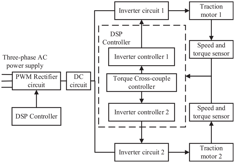
The dual-motor control scheme of the new frequency conversion control system.
Torque cross-coupled control method
The frequency conversion control method adopts vector control with fast speed response, high precision and good control performance. It is a control scheme combining rotor flux directional vector control and three-phase voltage source inverter space vector pulse width modulation. 14 Due to the nonlinear, strong coupling, and multi-variable properties of asynchronous motors, 15 the mathematical model in the A-B-C coordinate system is relatively complex. It is necessary to simplify the mathematical model of AC induction motor through 3s/2s transformation and 2s/2r transformation. Then the mathematical model of the AC asynchronous motor in the arbitrary rotating coordinate system d-q coordinate system is obtained. 16 When the magnetic linkage of the rotor rotating coordinate system d-q coordinate system is oriented to the M axis of the synchronous rotating coordinate system M-T coordinate system, the control equation of the vector decoupling control of the AC asynchronous motor can be obtained.


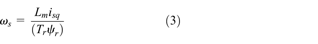
where
The torque cross-coupled control structure is shown in Figure 3. Using the principle of cross-coupled synchronous control, the torque of dual-motor is processed as a whole to form a closed-loop system. The coupling module redistributes the torque of each motor by detecting the torque deviation between the dual-motor. The speed regulator adopts the PI controller, whose function is to convert the given speed signal
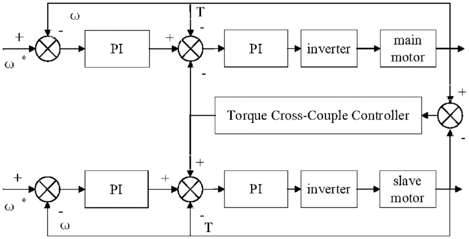
Structure of torque cross-coupled control system.
In order to facilitate the analysis, it is assumed that the parameters and controller models of the master motor and the slave motor are the same. Figure 4 is a block diagram of the corresponding system transfer function.

Transfer function block diagram.
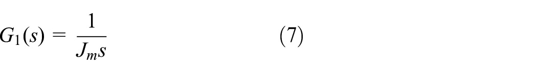
Taking the master motor as an example,
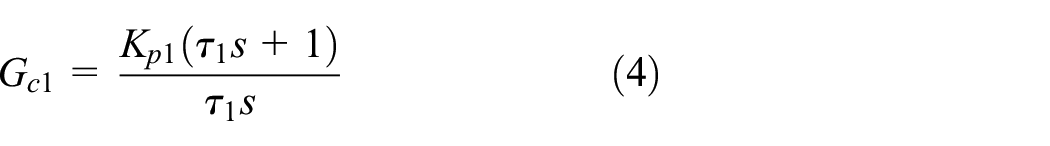

Where
In order to facilitate the analysis and design of the torque loop, the PWM is properly linearized, and the sampling time delay

Where
Where

When the feedback delay is ignored, both

Where

When considering torque cross-coupled control, the torque inner loop transfer function is presented in equation (11).

The system closed-loop input

Particle swarm optimization PID parameters by torque cross-coupled control
Particle swarm PID control structure is presented in Figure 5. The torque deviation of the dual-motor is used as the evaluation function of the particle swarm optimization algorithm, and the value of the fitness function is obtained by calculation. Then adjust the three parameters of PID according to the fitness of the function. In each iteration, the particle will track its own optimal solution Pbest and the optimal solution Gbest of the whole group, so that the control performance of the system can be optimized. 17
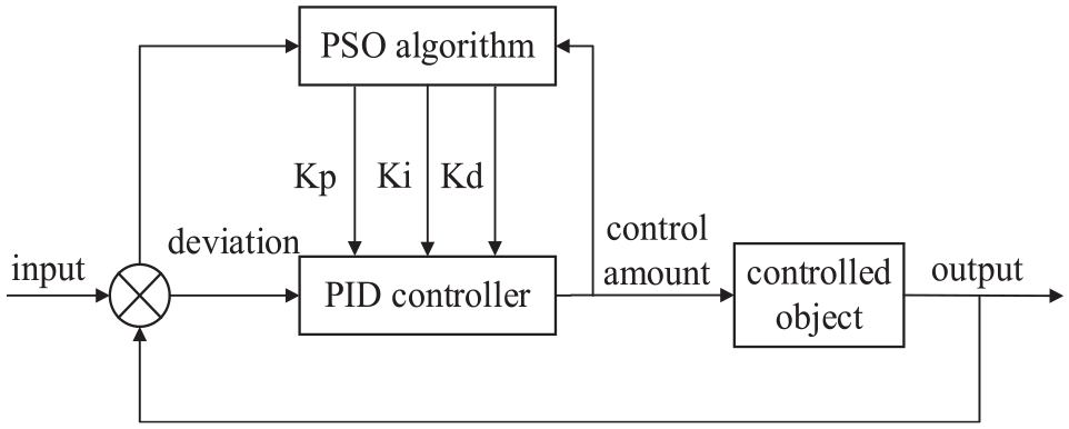
Particle swarm PID control structure.
During each iteration of the particle swarm algorithm, each particle knows its current position, its historical best position, and the best position among all particles in the world. Through the interaction of individuals in the population, the velocity and position of particles are updated to seek optimal solutions to complex problems.18,19
Suppose a group consisting of M particles is flying at a certain speed in D-dimensional space, and the state attributes of particle

Where

The individual optimal position is presented in equation (15).

The update formula of the particle position formula at time


Where
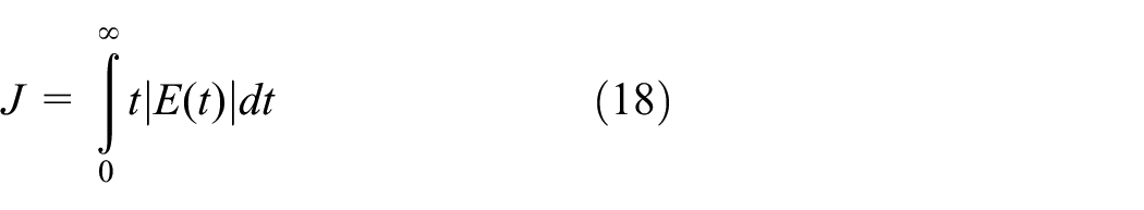
The particle swarm algorithm is used to determine a suitable set of PID control parameters, so that the system dynamic performance and power balance control accuracy can be optimized. The three control parameters of PID correspond to the parameters of the three dimensions of particle position. The ITAE index is used to calculate the particle fitness value. 20
Algorithm steps are described as follows.
Randomly initialize the particle swarm in the search space, The position information of the
The position information of each particle is used as the PID control parameter in turn, and its fitness value is calculated according to Equation (18).
Compare the fitness value of the particle with Pbest, and update Pbest and Gbest.
Update the speed and position of the particle according to the update formula of the speed and position.
Judging whether the termination condition is met, if so, stop the iteration, if not, go to step (2) to continue execution.
Simulation and experimental verification
Simulation verification
In order to verify the effectiveness of the dual-motor power balance control method of shearer traction unit based on the particle swarm optimization torque cross-coupled control. According to the above control principle, the power balance control model of torque cross-coupled control as shown in Figure 6, which is established in Matlab/Simulink.

Power balance control simulation mode with improved torque cross-coupled control.
The parameters of the dual-motor are shown in Table 1.
Motor parameters.

The parameters of the transfer function are optimized by particle swarm optimization algorithm. The initial population size is 100, the population dimension is 3, the maximum number of iterations is 100, and the learning factor is

Optimization curve of Kp, Ki, and Kd.
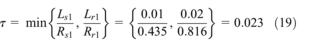
Take the master motor as an example, according to the relationship between the current loop bandwidth and the motor time constant, that is, time constant
Calculation of current loop parameters.

Each PI parameter of the current loop.


Speed loop PI parameters.

And through debugging in the simulation process, in order to achieve the optimal control effect, after debugging the speed loop
In order to make the motor load not exceed the rated torque of the motor 25N·m, the simulation parameters are set as the external load on the slave motor is set to 15 N m, and the load on the master motor is 15+10 s in 100πN m. The speed signal is 100 rad/s, the speed signal becomes 150 rad/s at 0.5 s, and the total simulation time is 1s.
The proportional action is to minimize the deviation and also to speed up the response. The introduction of the integral action is beneficial to eliminate the steady-state deviation. The introduction of differential action enables the system to respond according to the trend of deviation change. Appropriate differential action can speed up the system response, effectively reduce overshoot, improve the dynamic characteristics of the system, and increase the stability of the system. The output torques of the dual-motor are presented in Figure 8. The output torques of the dual-motor by the master-slave control is presented in Figure 8(a). When the motors are running, due to the lag of master-slave control, there is a phase difference between output torque of master motor and output torque of slave motor, and the dynamic performance is poor. The output torque of dual-motor using the unoptimized torque cross-coupled control is presented in Figure 8(b), and the output torque of dual-motor using torque cross-coupled control based on particle swarm optimization is presented in Figure 8(c).

Output torque of dual-motor for two control methods: (a) master-slave control, (b) unoptimized torque cross-coupled control, and (c) optimized torque cross-coupled control.
The output torque ratio curve of the dual-motor is presented in Figure 9. Figure 9(a) is the output torques of the dual-motor by the master-slave control, and Figure 9(b) is the output torques of the dual-motor by the unoptimized torque cross-coupled control. It can be seen from the comparison with Figure 9(a) and (b) that due to the hysteresis of the control method in the master-slave control, when the load fluctuates rapidly, the slave motor cannot give feedback in time, resulting in a large deviation in the output results. When the speed signal changes, even the ratio of the output torque of the dual-motor exceeds 2. The control performance of the torque cross-coupled controller is better than the master-slave control in the stable operation stage and when the speed signal changes. However, due to the different mechanical characteristics of the dual-motor, when the rotational speed changes, the torque ratio of the dual-motor still exceeds 1.1. Figure 9(c) is the output torque ratio curve of torque cross-coupled control based on particle swarm optimization. When the motors are running stably, the ratio of the output torque of the dual-motor is between 0.98 and 1.02. The torque ratio is also kept within 1.07.

Ratio of output torque of dual-motor for two control methods: (a) master-slave control, (b) unoptimized torque cross-coupled control, and (c) optimized torque cross-coupled control.
The master motor is loaded with step and ramp change torque, which is shown in Figure 10. The simulation parameters are set to be 15 N m for the external load of the master-slave motors. At 0.25 s, the system performs a step response, and the load signal of the master motor suddenly changes to 30 N m. At 0.7 s, the load signal becomes a ramp signal with a slope of 100. When it rises to 25 N m, it remains constant. At the same time, the initial traction speed signal of the dual-motor is given as 100 rad/s, and the simulation duration is 1 s. The output torque of the dual-motor is shown in Figure 11. When the system is running stably, the dual-motor can work well at the given torque and have good static performance. When the load of the master motor changes suddenly from 15 to 30 N m, the coupling module redistributes the torque deviation between the two motors and feeds it back to the control system. The dual-motor respond to the feedback signal at the same time, and the output torque is both 22.5 N m. When the master motor is loaded with step and ramp change torque, the two motor outputs each bear half of the total load, ensuring the balance of output power.

The master motor is loaded with step and ramp change torque.

Output torque of dual-motor.
In order to simulate the actual random load of the shearer traction unit, the main motor is loaded with random change torque, which is shown in Figure 12. The initial load of the dual-motor is 15 N m, and the master motor adds a random load of −10 to 10 N m at 0.5 s. The output torques of the dual-motor with random load is presented in Figure 13. As can be seen from Figure 13, when the load of master motor changes suddenly, the output torques of the slave motor can follow quickly, which indicates that the proposed control method has a fast response speed. The output torque deviation of the dual-motor is small, and the load is evenly distributed between the dual-motor, which indicates that the proposed control method has high power balance accuracy.

Load torque of dual-motor.

Output torque of dual-motor.
Test verification
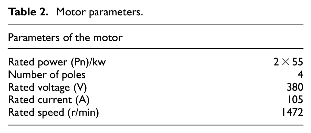
In order to verify the effectiveness of the proposed control method, a power balance test was carried out on the fully mechanized face MG400/930-WD of a coal mine. The length of the fully mechanized face was 280 m (Table 2). 21
Motor parameters.
After confirming that the system is working properly, the shearer starts cutting under no-load conditions. The data sampling frequency of the test system is 0.2 Hz. When master-slave control is used, the output torque of shearer traction unit dual-motor during the three cutting processes are shown in Figure 14. The corresponding output ratio in the three cutting are shown in Figure 15. In the initial stage, there is an obvious synchronization problem between master motor and slave motor, which leads to a very large ratio of the output torque of the two motors. In the stable operation stage, due to the complicated actual working conditions of the shearer, the follow-up of the slave motor to the master motor is also unsatisfactory.

When master-slave control is used, the output torque of dual-motor during three cuttings: (a) the output torque for the first cutting, (b) the output torque for the second cutting, and (c) the output torque for the third cutting.

When master-slave control is used, the ratio of output torque of dual-motor during three cuttings: (a) the ratio of output torque for the first cutting, (b) the ratio of output torque for the second cutting, and (c) the ratio of output torque for the third cutting.
When torque cross-coupled control is used, the output torque of shearer traction unit dual-motor during the three cutting processes are shown in Figure 16. The corresponding output torque ratios in the three cutting are shown in Figure 17. The results show that during the cutting processes, the output torques of the dual-motor in the shearer traction unit are basically the same. It can be seen from Figure 16 that when the load changes greatly during the working process, both motors can respond quickly, and have better adaptability to the complex working conditions of the shearer. The ratio of output torque of shearer traction dual-motor during the three cutting processes are shown in respectively. As can be seen from Figure 17, since the output torque of the dual-motor is small when the shearer is no-load, and there is a certain torque fluctuation in the motor output, the torque ratio of the dual-motor exceeds 1.2. When the shearer is cutting, the ratio of the output torques of the dual-motor is kept between 0.9 and 1.1, which effectively ensures the balance of output torques of dual-motor and verifies the effectiveness of the proposed control method.

When torque cross-coupled control is used, the output torque of dual-motor during three cuttings: (a) the output torque for the first cutting, (b) the output torque for the second cutting, and (c) the output torque for the third cutting.
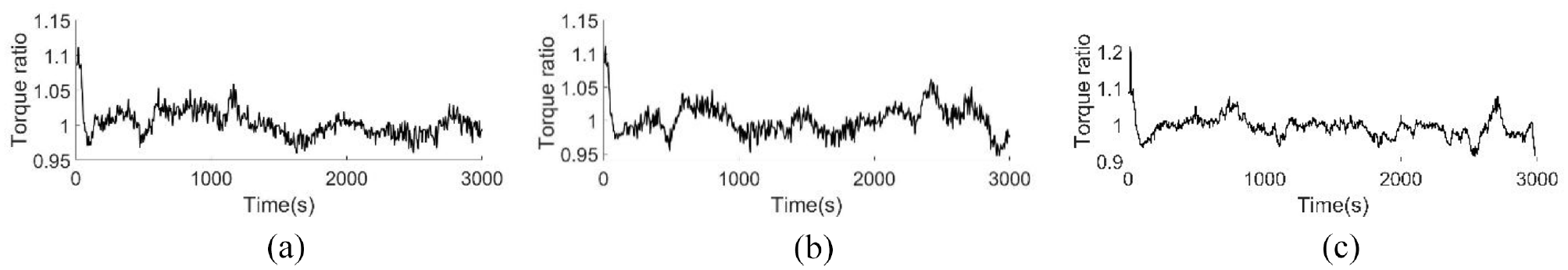
When torque cross-coupled control is used, the ratio of output torque of dual-motor during three cuttings: (a) the ratio of output torque for the first cutting, (b) the ratio of output torque for the second cutting, and (c) the ratio of output torque for the third cutting.
Conclusion
Aiming at the problem of energy-saving synchronous control of dual-motor in the shearer traction unit. a new frequency conversion control system of “common rectifier double inverter” is designed. And by adding the torque cross-coupled control link, the load torque of the dual-motor is compensated to the torque inner loop after correction operation. It can ensure the balance of the output torque of the dual-motor and reduce the risk of overloading a single motor.
A dual-motor power balance control method based on particle swarm optimization torque cross-coupled control is proposed. The optimization of PID parameters is realized, the difficult problem of PID parameter tuning in traditional torque cross-coupled control for torque complex change system is solved, and the control accuracy and stability of the system are improved.
The simulation comparative analysis and experimental verification of dual-motor power balance control under different load conditions are carried out by using the torque cross-coupled control and the traditional master-slave control method. The results show that the power balance control effect of the torque cross-coupled control method based on particle swarm optimization is better than that of the master-slave control method. The ratio of outputs is between 0.9 and 1.1.
Footnotes
Handling Editor: Chenhui Liang
Declaration of conflicting interests
The author(s) declared no potential conflicts of interest with respect to the research, authorship, and/or publication of this article.
Funding
The author(s) disclosed receipt of the following financial support for the research, authorship, and/or publication of this article: This work was supported in part by the General Projects of Shaanxi Coal Joint Fund in China under Grant 2019JLM-39 and the Innovative Talents Program of Shaanxi Province in China under Grant 2018TD-032.