
Abstract
In contour machining, contour error is a major factor affecting machining quality. In order to improve the performance of contour following, many control techniques based on real-time contour error estimation have been developed. In this paper, a Double Circle contour error estimation method is proposed. First, based on the kinematic information of the reference point on the command trajectory, five interpolation points closest to the actual point are obtained. Then the approximate contour error is obtained by employing the Double Circle approximation method. Compared with the common contour error approximation methods, the proposed method can achieve high precision approximation. In addition, according to the proposed contour error approximation method, the cross-coupled control strategy is improved. Experiments prove the effectiveness of the proposed estimation method and control strategy.
Introduction
Attaining high machining accuracy is a key aspect of CNC (Computerized Numerical Control) machining. Contour error, defined as the shortest distance from the actual position to the desired trajectory, is an essential indicator to measure the product quality. In a CNC machine, contour error is inevitable as a result of various factors, such as unmatched dynamics between different axes, nonlinearities, 1 servo lag, 2 and disturbances. 3 Due to these factors, improving the tracking performance of individual axes is minimal effectiveness in reducing contour error.
To complete a satisfactory contour following the task, it is necessary to calculate and compensate the real-time contour error in the CNC motion controller. The calculation of the contour error is usually complicated. Limited by the real-time computation ability of CNC, computing the exact contour error on each sampling cycle is sometimes difficult. In fact, estimated contour error is widely applied instead of the actual contour error.
Because high precision contour estimation plays an important role in contouring control, it has been a major topic of research during the past 40 years. Cross-coupled control (CCC), first proposed by Koren 4 in 1980, offered an effective way of contour control. This model approximated the linear combination of tracking errors as estimated contour error and compensates for the servo controller in each axis. Inspired by CCC, more approximate methods of contour curve are proposed. The vector from the actual point to the perpendicular on the tangent passing through the nearest reference point is a tangent-line based contour error estimation proposed by SS Yeh et al., 5 K. Srinivasan et al. 6 and CC Lo et al. 7 Cheng and Lee 8 modified the tangent-line-based estimation by replacing the tangent-line of command point with the synthetic velocity vector at the reference point and the actual position to determine the delayed point. In recent years, the approximate accuracy of this method has been improved. 9 Koren et al. 10 proposed that contour error is proportional to tracking error in biaxial machining and the gains of the CCC are variable. Although they4–10 can obtain high estimation accuracy for straight line and small curvature trajectory in line interpolation or curve interpolation form, these methods have little effect in the case of large curvature trajectory and high-speed feeding.
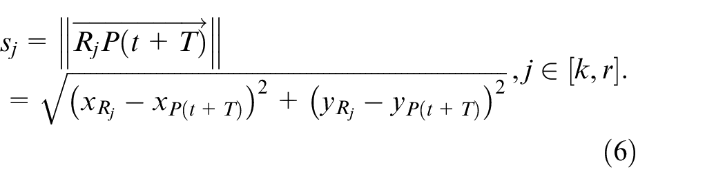
To address this problem, it has been studied by many researchers using different means. In 2007, Chen and Wu 11 presented a novel equivalent error consisting of equivalent contour errors and tangential error for multi-axis motion system. Chiu and Tomizuka 12 proposed a contour error model in which the axes coordinate system is transformed into Tangential-Normal-Bidirectional task frame. In Altintas and Khoshdarregi 13 and Yang and Altintas, 14 contour error is approximated by the normal component of the tracking error in the Frenet Frame. Moreover, Altintas and Sencer 15 presented a novel contour error estimation model which is consisted of tool axis orientation errors and tooltip position in Frenet Frame. For curve path command, circular approximation with a moving TDN frame is proposed by Yang and Li. 16 Zhao et al. 17 defined the estimated contour as a circle determined by three interpolation dots closest to the actual position, so the estimated contour error is the shortest distance between the actual position and the circle. In the approaches proposed in Zhu et al., 18 Hu et al., 19 Wang et al., 20 Zhao et al., 21 and Shi and Lou, 22 real-time contour error estimation based on Taylor expansion approximation employed a point-to-curve distance function to calculate directly. However, due to the characteristics of Taylor expansion approximation, these methods can achieve good results only when the actual point and the desired point are close enough. In Pi et al., 23 Ferguson curve is employed to estimated contour error. In repetitive machining process, iterative based methods were also applied to compensate the contour error.24,25 By adjusting the weight coefficient in the prediction model, the weighted average value in the observation area is minimized, and then the contour error is pre-compensated. 26 In addition, some researches based on the global task coordinate framework (GTCF) also achieve a high accuracy approximation of the contour error.27–29 To have good parameter adaptability and disturbance robustness, a LARC contouring control scheme was developed by Hu et al. 28 Within the framework of GTCF,31–33 researched on contouring control and synchronized control for dual-linear-motor-driven gantry by integrating both motion coordination of multi-axes and synchronization of redundant actuators.
Generally, approaches of contour error estimation are focused on three types: employing the tracking error and some motion information, for example, the velocity of the reference point and actual position; simplifying the calculation of contour error by transforming the axis coordination into task coordination; estimating the vector of contour error by iterative approximation. Despite the significant performance of the aforementioned approaches, considerable motion information and parameter-based reference trajectory are required in these models.
Depending on the experiments in Chen et al., 9 the performance of the Three-Points Circle approximation approach proposed in Zhao et al. 17 is remarkable. Moreover, Ming Yang et al. 30 extended this method to five-axis contour error control. However, as the actual position moves, the Three-Point Circle changes as the nearest interpolation point changes. This results in a mutation of the estimated contour error. Motivated by Zhao et al., 17 a novel approximated model to estimate the contour error in real-time for the middle and low-grade CNC system is proposed in this paper. Since the contour error of long linear trajectory and long circular trajectory can be accurately calculated and decoupled to each axis for compensation, 16 this paper focuses on the contour error approximation and compensation for continuous free-form trajectory.
In this paper, the Double Circle approximation method is proposed on the basis of the Three-Point Circle method. Two circles are constructed by five nearest interpolation points, and the shortest vectors from the actual position to the two circles are calculated respectively. Usually, the two closest points from the actual position to the two circles are distributed on both sides of the command trajectory. The average vector of the two shortest vectors is used to approximate the actual contour error, which theoretically has higher approximation accuracy than the Three-Point Circle method. The Double Circle method avoids the problem of low approximation accuracy when the actual point is far away from the nearest interpolation point, that is, near the midpoint of the two interpolation points. It also alleviates the abrupt change problem of approximate contour error caused by the change of nearest interpolation point in the Three-Point Circle method. Then, the calculation process of the contour error of the Double Circle estimation is derived. According to the form of estimated contour error, the typical CCC control strategy is optimized.
Figure 1 illustrates the flowchart of the presented contour error compensation. First, the interpolator generates the interpolating points of the reference trajectory. Then the interpolation points are cached in the buffer; the relationship between the sampling period and the interpolation period is confirmed; the closest interpolation point in the buffer is calculated according to the actual point position of the current sampling period; then the four interpolation points are obtained according to the approximate model of Double Circle estimation, and the approximate contour error is calculated; then the gains of cross-coupled controller are calculated. Finally, input to the proposed CCC controller.
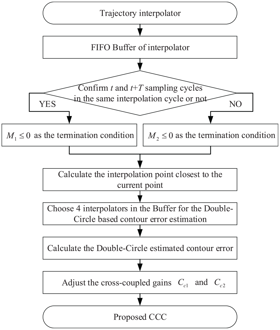
Overview of the proposed method.
This paper is organized as follows. Section 2 introduces the proposed contour error approximation model of the biaxial machine tool feed drive. Section 3 describes the calculation process of the estimated contour error in detail. In section 4, the optimized cross-coupled control scheme based on the proposed approximate model is given. Experiment results for Ellipse trajectory, Lemniscate trajectory, and Dolphin trajectory are illustrated in section 5 to verify the effectiveness of the proposed contour control strategy.
Proposed estimated model of contour error
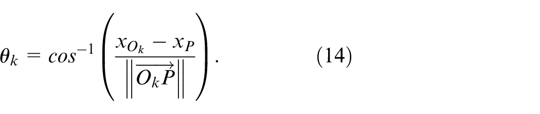
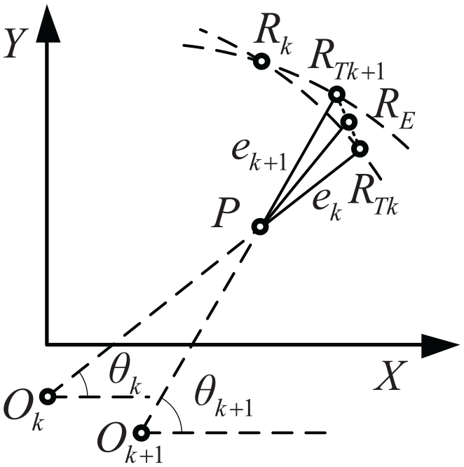
As shown in Figure 2,
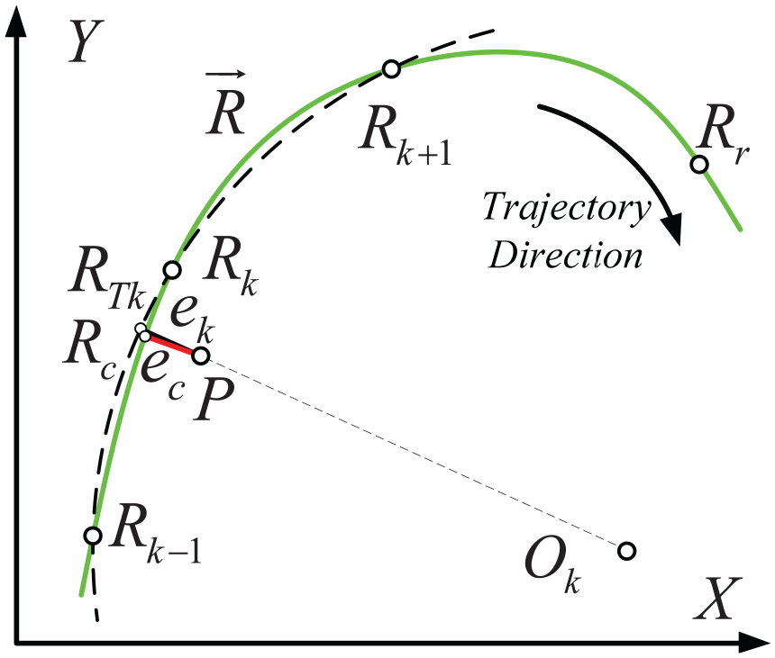
Define of contour error and Three-Points Circle estimated contour error.
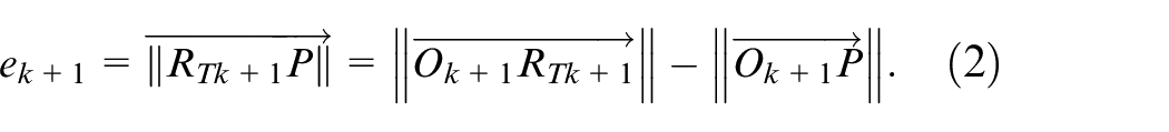
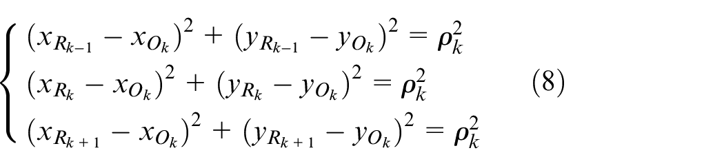
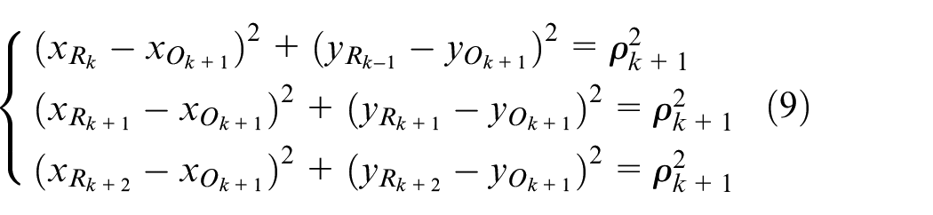
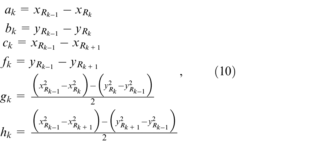
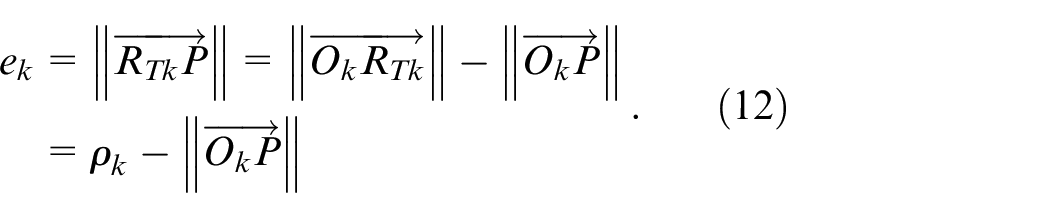
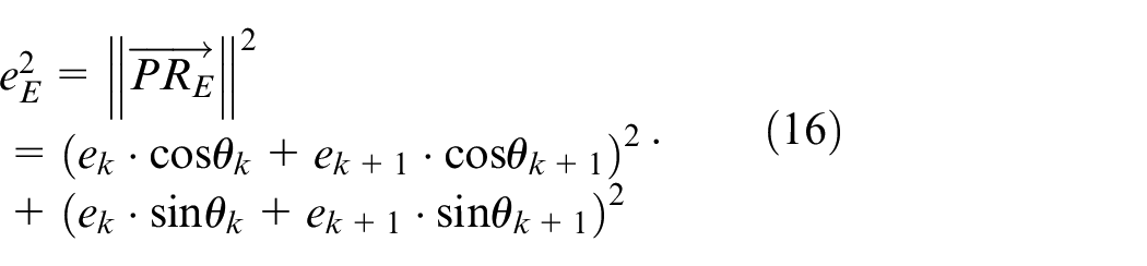
Suppose the two adjacent interpolation points from Rk be Rk-1 and Rk+1, and the center of the circle Ck through Rk−1, Rk, and Rk+1 be the point Ok. RTk is the nearest point to the circle Ck. So, the shortest distance ek from P to the circle Ck can be calculated
The ek is the Three-Points circular approximation. To improve the approximate accuracy and adaptability when the closest interpolation point Rk changed, the third nearest interpolation point from P, Rk−2 or Rk+2 is introduced in Figure 3. Comparing
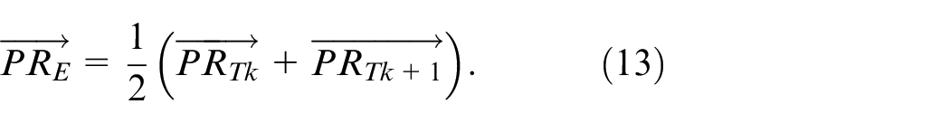
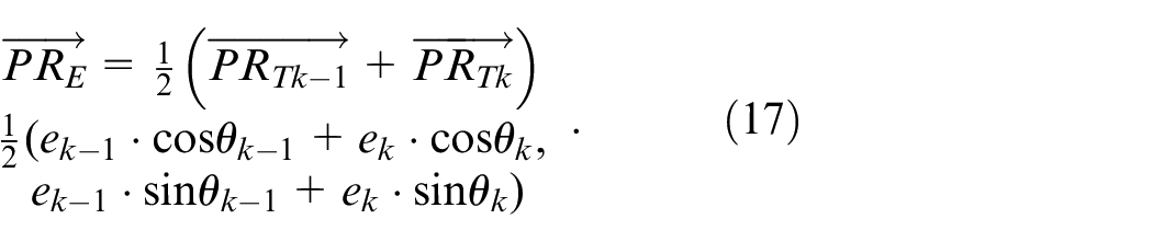
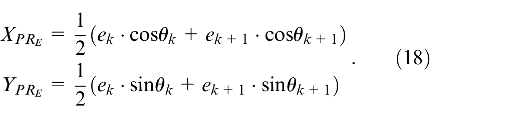
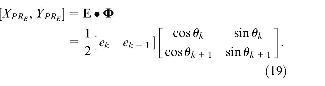
Define RE be the midpoint of
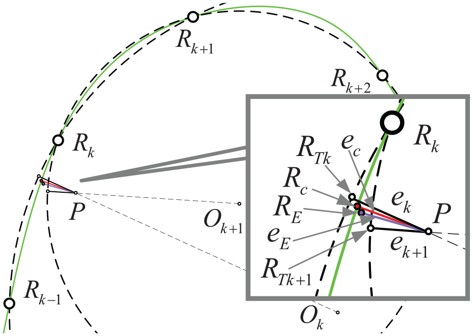
The proposed Double Circle contour error estimation.
Contour error estimation algorithm
FIFO buffer of interpolator
In the presented approach, the efficiency of the estimated model is determined by finding the four interpolation points and the calculation of the ek and ek+1 mostly. In order to seek the nearest four points faster, a FIFO (first-in, first-out) buffer of the interpolation points is designed for the interpolator in the CNC system. The position information of the interpolation points is stored in the buffer and the volume of the buffer, m, depends on the response speed of the feeding system. The buffer updates in each interpolating cycle as the program proceeding.
First of all, it is necessary to search for the closest interpolation point Rk to P. Owing to the hysteresis of the feeding system, Rk is lag behind the current reference interpolation point Rr usually. Store Rr and m−1 points after Rr in the buffer. Assume that D:(d1, d2,…, dm) be the distance between P and the points
Starting from i = 1, compare di and di+1 one by one, until
Generally speaking, the sampling cycle T of the position loop and velocity loop of the servo system is shorter than the interpolation cycle ts of CNC system and
and the terminating condition of comparison be
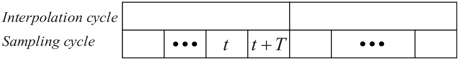
t and t + T sampling cycles in the same interpolation cycle.
If the t+T sampling cycle is in the new interpolation cycle, as shown in Figure 5, the current reference interpolation point Rr is replaced by Rr+1 and the buffer will change with Rr−m+1 in and Rr+1 out. In this case, t is the last sampling cycle in the past interpolation cycle. According to Rk and Rr, the lag time of the feeding system can be estimated by
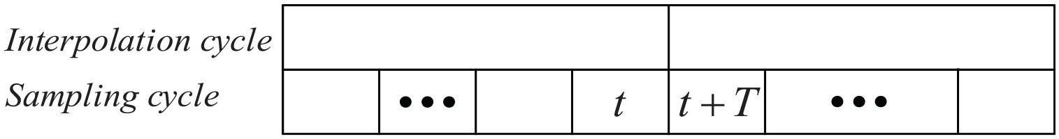
t and t + T sampling cycles in different interpolation cycles.
In the event of external disturbance or other circumstances, P(t+T) may be farther away than P(t) to the reference point, and the tracking error may increase significantly. The calculated closest point Rk for P(t) has no reference significance in the t+T sampling cycle. Apparently,
Calculation process of the proposed contour error approximation algorithm
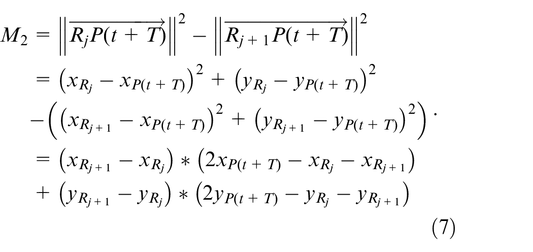
After the nearest interpolation point Rk to P has been found in the Buffer of the interpolator, the fourth point can be obtained by comparing
in which
Assuming that
Then (1) can be rewritten as
According to the previous definition of
Assuming
Then one can have
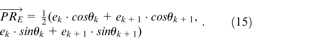
So, the estimated contour error
In the case of
Schematic illustration of the computation of
When
Proposed motion control scheme
Figure 7 shows the typical cross-coupled control strategy for a biaxial motion system.
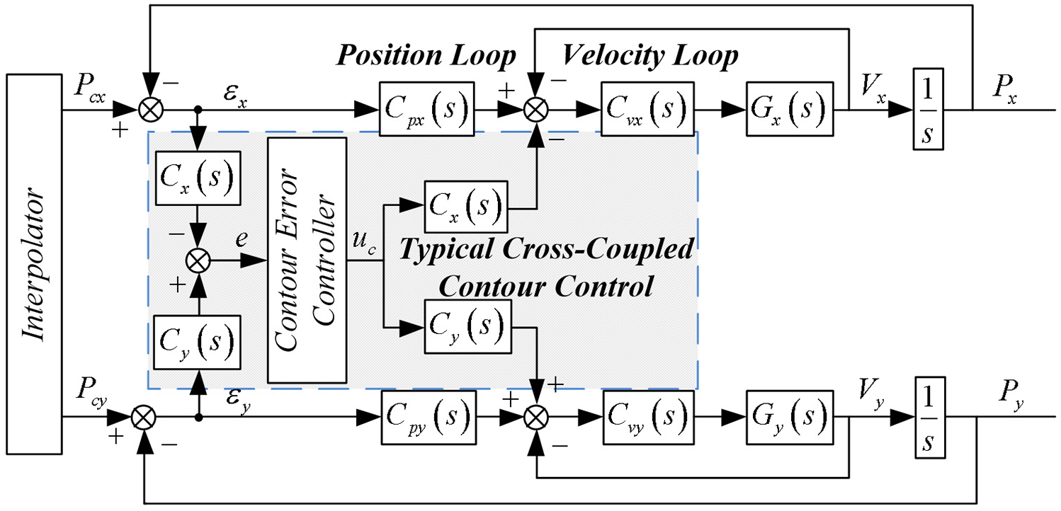
Block diagram of the typical cross-coupled control system.
In the typical CCC scheme for contour error, the estimated contour error should be calculated based on the tracking error of each axis, and then the estimated contour error should be input into the CCC controller. Finally, the control variables for contour error are decoupled and compensated to each axis respectively. In general, three steps need to be taken: (1) calculate the estimated contour error; (2) input it into the CCC controller; (3) decouple the control variables and compensated to each axis.
According to (12),
Assuming
Therefore, reducing the estimated contour error equivalent to reducing
The proposed control strategy is shown in Figure 8. The optimized CCC scheme in this paper has the same process as the typical one. The difference is that the approximate method of contour error is the proposed Double Circle method, and
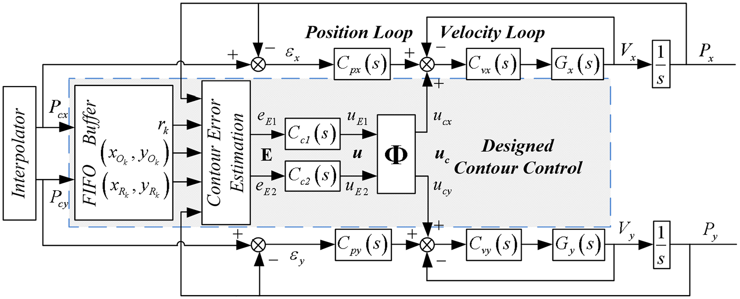
Block diagram of the presented control scheme for a biaxial motion system.
By applying the CCC controller
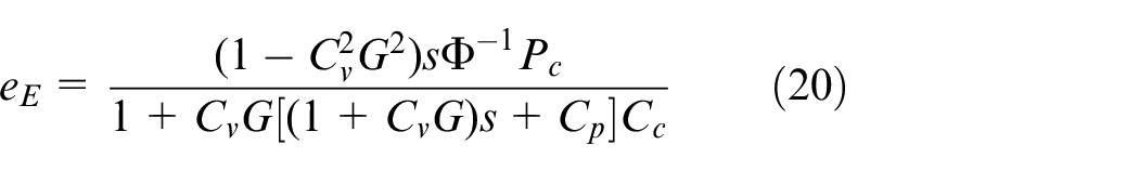
Let

and

Then, the relationship between
According to Yang and Li,
16
the function
Step 1: Identify the transfer functions of the individual axis
Step 2: Without CCC controller, a stable controller
Step 3: A I-type cross-coupled controller
Step 4: Check the stability of the CETF.
Step 5: Finish if Step 4 are satisfied, otherwise return to Step 3 and tune the gains of
Under different operating conditions, the adjusted
Simulation and experimental results
Experimental setup
The experiments are carried out on a three-axis CNC machine tool, TSIM-VMA8050, as shown in Figure 9. This system is a semi-closed loop system and the position sensing is provided by the encoder of each servo motor. The machine tool is equipped with TSNC-SX-A1 CNC system, which is developed by our laboratory. The interpolation cycle and the sampling cycle of the NC system are both set to 2 ms throughout the experiments. In order to avoid the impact of shock and vibration, the S-type acceleration and deceleration strategy is imposed by the look-ahead feedrate planning module embedded in the interpolator. In the motion system, the velocity and position loops of each single-axis are enabled and PID controllers are also tuned.
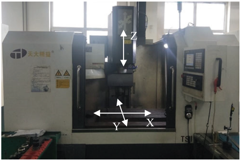
Three-axis machine tool employed in the experiments.
Comparative experiments of approximate approaches
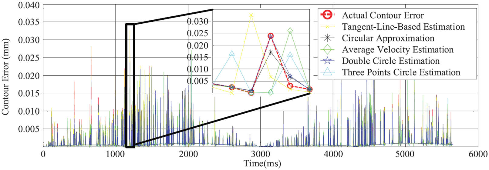
In this part, the estimation performance of the proposed method in this paper is compared with four common estimation methods, which are Tangent-Line-Based estimation, 5 Circular approximation, 16 Average Velocity estimation, 9 and Three-Points-Circle estimation. 17 Ellipse trajectory and Lemniscate trajectory are executed to assess the performance of different approximation approaches. In these experiments, the estimated contour error with the estimation methods is calculated in real-time, and there is no contour compensation mechanism in the motion system. In addition, the actual contour error is calculated offline. The experimental results are shown in Figures 11 and 13.
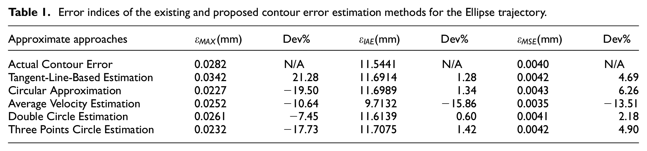
The command trajectories and actual contour of Ellipse and Lemniscate are shown in Figures 10 and 12. Figures 11 and 13 depict the estimated errors in the approximation methods mentioned above and actual contour errors. The corresponding contour error statistics are presented in Tables 1 and 2. The performance index “Max” represents the maximum absolute contour error, “IAE” the integral of the absolute contour error and “MSE” the mean squared error of contour error.
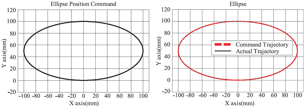
Ellipse command and actual trajectory.
Performance of different estimation methods for the Ellipse trajectory.
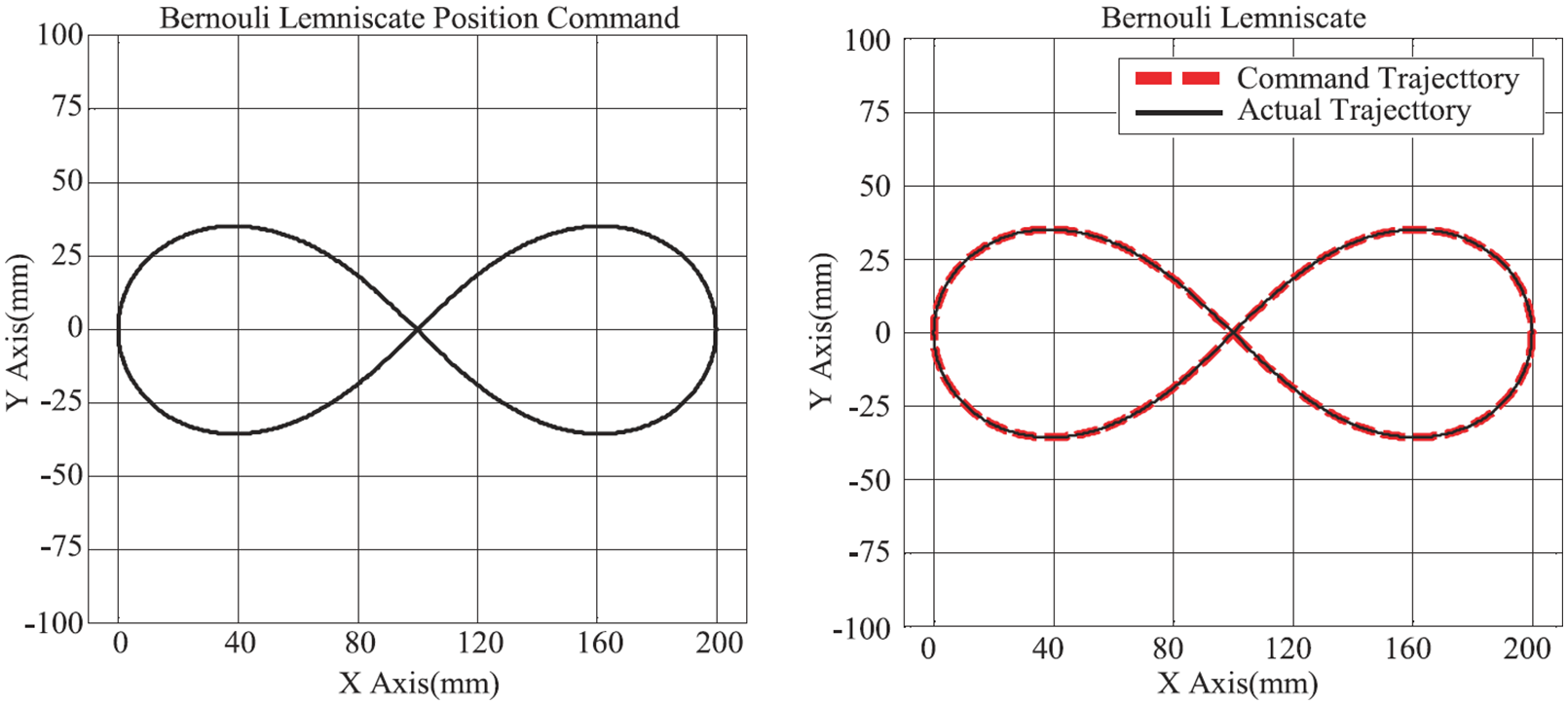
Lemniscate command and actual trajectory.
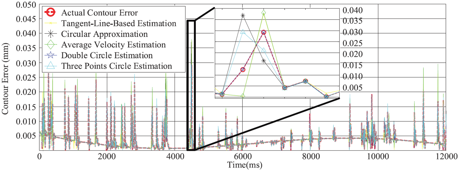
Performance of different estimation methods for the Lemniscate trajectory.
Error indices of the existing and proposed contour error estimation methods for the Ellipse trajectory.
Error indices of the existing and proposed contour error estimation methods for the Lemniscate trajectory.
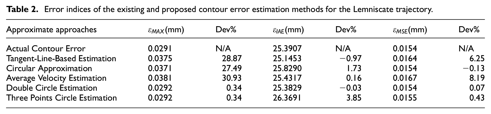
As can be seen from Tables 1 and 2 that in the two experiments, the maximum of approximate contour error estimated by Double Circle method is 0.0261 mm and 0.0292 mm, which is −7.45% and 0.34% deviation compared with the maximum actual contour error of 0.0282 mm and 0.0291 mm. In the Ellipse trajectory experiment, compared with other approximation methods, the improvement is about 3% at least; in the Lemniscate trajectory experiment, except that the maximum contour error of Three Points Circle method is the almost same as the one of Double Circle method, it improves at least about 27% compared with other approximation methods. In the two experiments, the IAE of Double Circle method is 11.6139 mm and 25.3829 mm, which is the closest to the IAE of actual contour error 11.5441 mm and 25.3907 mm, and the deviations are 0.60% and −0.03%, respectively. The MSE of Double Circle method is 0.0041 mm and 0.0154 mm, which also has the smallest deviation from the MSE of actual contour error. Generally, the contour error estimated by the proposed approach can estimate the actual contour error more accurately.
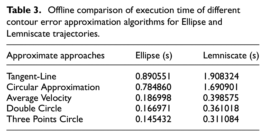
In order to prove the efficiency of the proposed Double Circle estimation method, the execution time of different contour error approximation algorithms is compared offline in MATLAB after the motion is finished. They are executed on a personal computer with 1.9 GHz CPU.
It can be seen from Table 3 that Three Points Circle method has the highest algorithm efficiency; Double Circle method takes the second place; Average Velocity method is close to Double Circle method; Circular approximation and Tagent-Line method have the lowest efficiency. Because the Double Circle method is calculated on the basis of Three Points Circle method, the time is about 15.43% longer than that of Three Points Circle method. But it was 10.07%, 78.69% and 81.17% faster than Average Velocity method, Circular approximation method and Tangent Line method, respectively. Double Circle method is still an effective approximation method of contour error.
Offline comparison of execution time of different contour error approximation algorithms for Ellipse and Lemniscate trajectories.
The contrast experiments on contour error compensation
In this section, the Dolphin trajectory is conducted on the CNC machine to verify the effectiveness of the CCC proposed above. The trajectory in Figure 14 is carried out without CCC, circular approximation based typical CCC, and proposed double circle estimation based CCC respectively. Figure 15 shows the machining result with proposed Double Circle estimation based CCC. Figure 16 presents the tracking error of each axis and the contour errors are given in Figure 17. The contour error indices are listed in Table 4.
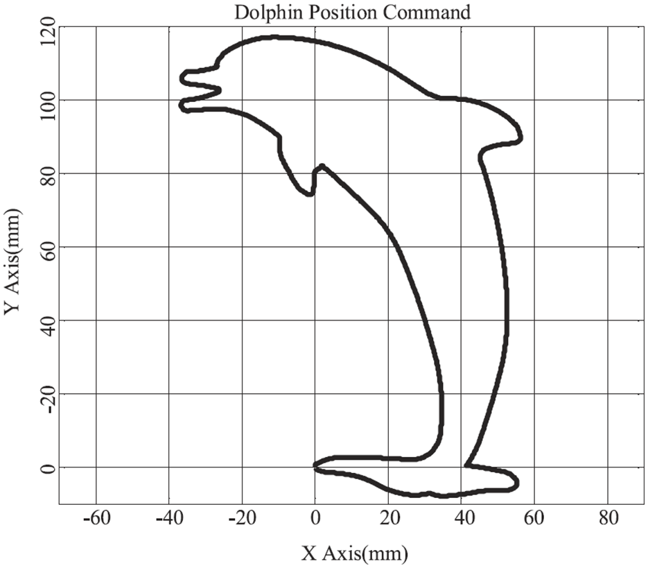
Dolphin command and actual trajectory.
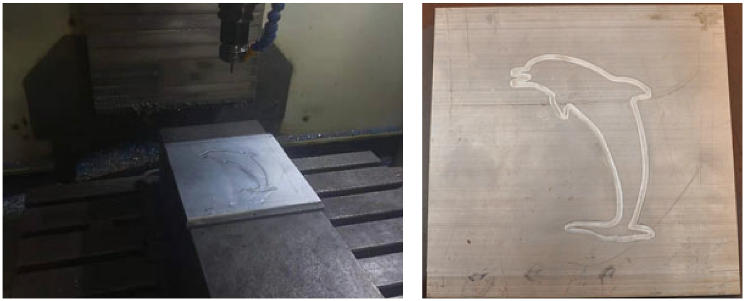
Machining result for Dolphin trajectory with double circle estimation based CCC.
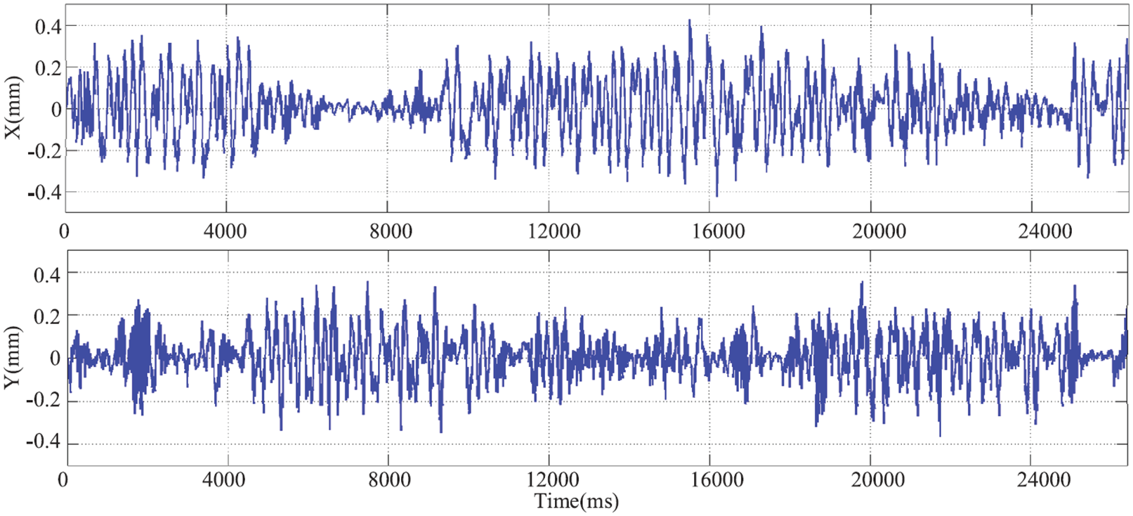
Tracking error of X/Y axis for Dolphin trajectory.
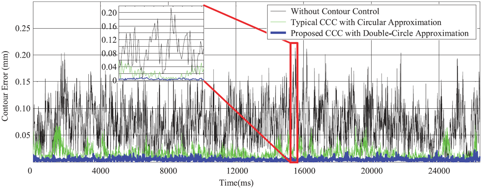
Control performance of proposed CCC, typical CCC, and without contour control.
Contouring performance of different control approaches.
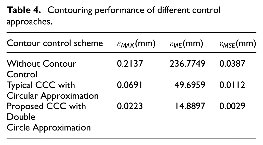
It is seen from Figure 17 and Table 4 that the maximum contour error is 0.2137 mm without CCC contour control mechanism. In the case of typical CCC with Circular approximation enabled, the maximum contour error is 0.0691 mm, which is 67.66% lower than that without CCC. The typical CCC with Circular approximation achieves the effect of contouring control. When the proposed CCC with Double Circle method enabled, the maximum contour error is 0.0223 mm, which is only 10.44% of that without CCC. The IAE of the proposed CCC is 14.8897 mm, which is reduced by 93.71% compared with the IAE without CCC and 70.04% compared with the IAE with typical CCC. The MSE of the proposed CCC is 0.0029mm, which is 92.51% lower than the MSE without CCC and 74.11% lower than that with typical CCC. Besides, the contour error is well controlled with the proposed CCC in the whole process of contouring motion. Therefore, the control strategy proposed in this paper has a significant effect on contour error control.
Conclusion
Contour tracking control is a necessary control method when the machine tool completes the contour machining task. The accuracy of contour error estimation will directly affect the error compensation effect of machine tools, and ultimately affect the machining quality of parts. In this paper, a Double Circle contour error estimation method is proposed based on the Three-Point Circle method. Firstly, according to the kinematic information of the reference point and the actual position, four interpolation points closest to the actual point are obtained and two circles are constructed. Then, the average vector of the shortest vector from the actual position to the two circles is used to approximate the actual contour error. Subsequently, the calculation process of contour error is given. Considering the characteristics of contour error, an optimized CCC is proposed and the design process of controller
Footnotes
Declaration of conflicting interests
The author(s) declared no potential conflicts of interest with respect to the research, authorship, and/or publication of this article.
Funding
The author(s) disclosed receipt of the following financial support for the research, authorship, and/or publication of this article: This project is supported by National Natural Science Foundation of China (Grant No. 51975402).
Data availability statement
The data used to support the findings of this study are available from the corresponding author upon request.