
Abstract
Aiming at the free-form curve contour tracking error problem of CNC machining, a cross-coupled controller based on Fuzzy PID using an improved PSO algorithm is proposed. First, the exact formulas of the linear and circular arc contour errors under a plane trajectory are derived, and an estimation method for the free curve profile error under a plane trajectory based on the principle of approximate approximation of preferred points is designed. Second, a cross-coupled controller based on Fuzzy PID using an improved PSO algorithm is achieved. An improved PSO algorithm, whose learning factor is adjusted with the inertia weight, is used to optimize the controller parameters and achieve contour tracking of the free curve. Finally, a two-dimensional biaxial experimental platform is used to test the proposed method. The results demonstrate that the optimal gain parameters obtained by the proposed strategy can significantly improve contour control accuracy in biaxial contour tracking tasks. The proposed contour error control scheme can achieve not only a nearly perfect contouring error estimation, but also an obvious promotion of contouring accuracy.
Introduction
Contour error is an important research topic in contour following tasks such as computer numerical control (CNC) machine tool machining and welding,1–3 the contour error is not only affected by the following error of a single driver, but also closely related to the synchronous movement between the drivers. 4 In the field of numerical control machining, the errors of servo system generally include position following error and trajectory contour error, the position following error is the difference between the actual position and the expected position, and the trajectory contour error is the distance from the actual position to the expected contour.5,6 Domestic and foreign scholars have done a lot of research on contour error. Song et al. 7 defined the five-axis contour error five joint space, by adjusting the uniform unit of the five joints, and with the concept of the generalized curve, for the definition of joint space contour error, a third-order estimation algorithm is proposed. Bo et al. 8 proposed a double circle contour error estimation method. According to the kinematic information of the reference point on the instruction trajectory, five interpolation points closest to the actual point were obtained, and then the approximate contour error was obtained by using the double circle approximation method. Conway et al. 9 proposed a method based on calculating polynomial curve to calculate contour error, which will also have a large amount of calculation.
Contour error reduction is an issue of much concern. The control of contour error is generally divided into single-axis decoupling contour control and multi-axis coupling contour control. Improving the following performance of a single axis has little effect on the small contour error. 6 In order to better complete the contour following task, Koren et al. 10 firstly proposed a two-dimensional contour cross-coupled control (CCC) method in the 1980s. The contour error control model is mainly based on the error of each feed axis. Each single-axis controller not only adjusts its error but also adjusts other feed axis errors, so that each independent single-axis servo system becomes a whole cross-coupled system. The key techniques in the cross-coupling structure mainly include the design of the contour controller and the selection of the cross-coupling gain, based on which some scholars have studied the design of the contour error controller, Chen et al. 11 used the H∞ theory to design a cross-coupled controller, which improved the robustness of the system. Liu et al. 12 used the characteristics of the servo structure to establish a prediction model for following error. Based on considering the friction damping of the transmission mechanism, a LuGre friction compensation strategy that considered friction and external interference at the same time was proposed. Zhang et al. 13 coordinated following error and contour error through multi-step prediction, rolling optimization, and feedback correction ideas in generalized predictive control to obtain the optimal control input signal. Han et al. 14 proposed a tooth profile error modeling method and an adaptive electronic gearbox cross-coupled controller for internal meshing dynamic honing. Zhou et al. 15 proposed a new dual-axis integrated control strategy, using a disturbance observer in a cross-coupled architecture to compensate for friction. Wang et al. 16 designed sliding-mode structure control algorithm and proposed a cross-coupled control strategy consisting of a sliding-mode following controller, a disturbance observer, and an adaptive fuzzy PID, but the sliding-mode structure is prone to chattering. Sun et al. 17 proposed a dynamic compensated fast adaptive robust control method to reduce the influence of parameter estimation error and unmodeled dynamic disturbance. Shang et al. 18 and Zhang et al. 19 proposed an improved cross-coupled control scheme combining real-time contour error estimation and model-free adaptive control (MFAC).
In addition, many advanced PID and fuzzy control strategies have also been developed. Ling et al. 20 proposed a position domain iterative learning controller with PID iterative learning control and PD cross-coupled control. Chen et al. 21 proposed an adaptive cross-coupled two-degree-of-freedom PID control strategy and designed two compensators to eliminate the contour error in biaxial motion. Yao et al. 22 established the mathematical model of the compensation and decoupling link, designed the cross-coupled fuzzy PID controller, and combined it with the complete decoupling compensation method. However, it has shortcomings in the optimization of controller parameters, and poor adaptability and robustness. At present, most contour error methods are designed on the basis of CCC, such as sliding mode structure, 16 Model-free adaptive control, 19 fuzzy PID control, 22 and model reference adaptive control, 23 and so forth, all have their own advantages and contributions within their applications, but there are also problems of accuracy and real-time. The current cross-coupled control method of contour error has been well developed and applied, but there are still some shortcomings in the optimization of controller parameters.
This paper provides an in-depth discussion on the estimation and control of contour errors based on the traditional contour error cross-coupled control problem. The main contributions of this paper are as follows:
The contour error estimation calculation method is discussed, and the test shows that the contour accuracy of the method can meet the requirements even if the curve curvature is large.
In the contour control, the PSO algorithm is improved to optimize the fuzzy PID control parameters so as to perform adaptive fuzzy PID contour error cross-coupled control.
The effectiveness of the proposed method is verified. The contour error tracking experiments are carried out for different shapes of NURBS curves, and high accuracy tracking of 2D contours is achieved.
The rest of the paper is organized as follows. The “Contour trajectory error estimation algorithm” section presents the calculation of the contour error under free trajectory with high estimation accuracy based on the principle of preferred point approximation. The “Improved PSO algorithm to optimize fuzzy PID cross-coupled controller” Section presents the control method of fuzzy PID based on PSO optimization. Experimental results are given in “Verification of two-dimensional x-y axis experimental platform” Section, and conclusions are given in “Conclusion” Section.
Contour trajectory error estimation algorithm
In CNC machining, contour accuracy plays an important role in multi-axis servo systems. 16 and real-time acquisition of contour error values is a prerequisite for controlling contour errors. Existing two-dimensional plane contour error calculation models include contour estimation models of arcs, straight lines, and free curves.
Calculation of contour error of straight line and arc
Divided by spatial dimensions, contour error can be divided into two-dimensional plane trajectory contour error and three-dimensional space trajectory contour error. This article only discusses contour error control under plane trajectory, if the ideal contour is a straight-line trajectory or a circular arc trajectory, the contour error can be accurately obtained. The principle diagram for calculating the contour error of a straight line or arc trajectory is shown in Figure 1, R is the desired position point, P is the actual position point, Rp is the vertical foot point on the ideal contour, and O is the center of the arc trajectory. According to the schematic diagram, the calculation formulas of the two are listed separately.
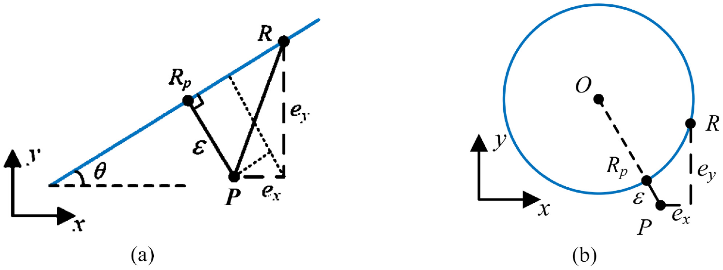
Computation for contour error of linear and circle trajectories: (a) linear trajectory and (b) arc track.
For a straight-line trajectory, the precise calculation formula for its contour error can be calculated as:

where ex and ey are the components of the following error on the x-axis and y-axis, respectively; θ is the angle between the linear trajectory and the x-axis.
For the arc trajectory, the precise calculation formula for the contour error as:

where ‖P-O‖ represents the two norms of P-O. Substitute the coordinates of each point into equation (2) to obtain:
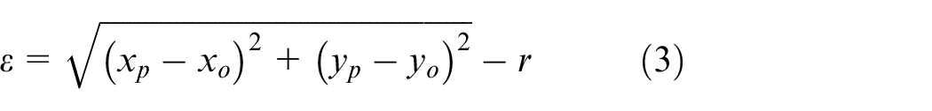
where r is the radius; xp and yp are the coordinates of the actual position point P; xo and yo are the coordinates of the center O of the arc trajectory.
Free curve contour error estimation algorithm
The contour error is defined as the shortest normal distance from the actual position of the machine tool to the contour curve, and the true value of the contour error of the free curve is difficult to calculate analytically, so it is usually approximated. The estimation of the free curve contour error in this paper is inspired by Chen et al. 24 The contour error estimation method does not need to consider the command position and speed information and has good accuracy and real-time. Figure 2 shows the principle diagram of the estimation method.
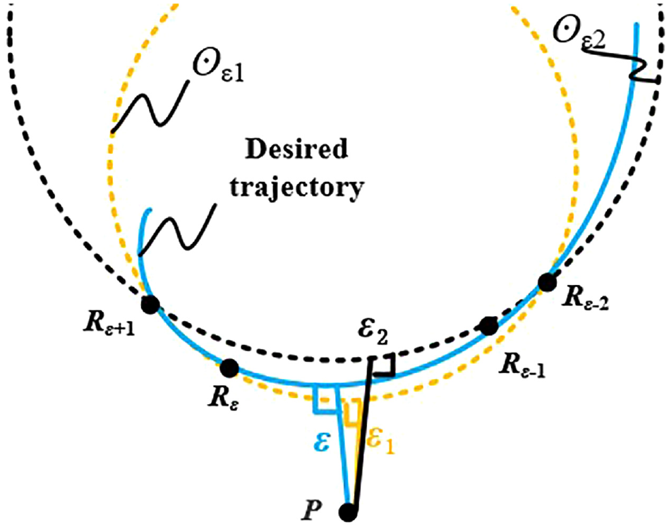
Schematic diagram of free curve contour error.
In Figure 2, P is the current position point, the interpolation point closest to the point P on the ideal contour is Rε, trace back from the command position R, when the condition
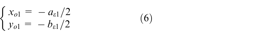
If the coordinates of the four interpolation points are Rε+1(xε1, yε1), Rε (xε2, yε2), Rε-1(xε3, yε3), Rε-2(xε4, yε4), respectively, then the center of the circle over the points Rε+1, Rε, Rε-1 is ⊙ε1(xo1, yo1), the radius is rε1, and the center of the circle ⊙ε2(xo2, yo2) can be obtained in the same way. The expression of the circle can be formed by the following quadratic equation.
The expression of the circle can be composed of the following binary quadratic equations:

Substitute the coordinates of points Rε+1, Rε, Rε-1 into equation (4) to find the coefficient of circle ⊙ε1. Then aε1, bε2, cε3 are calculated as:
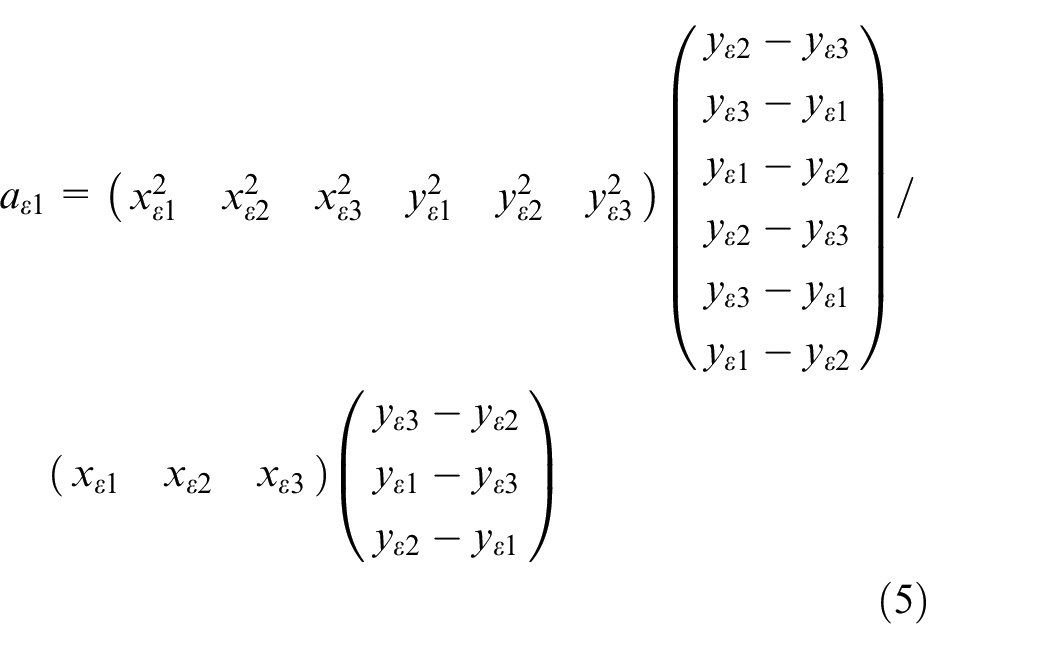
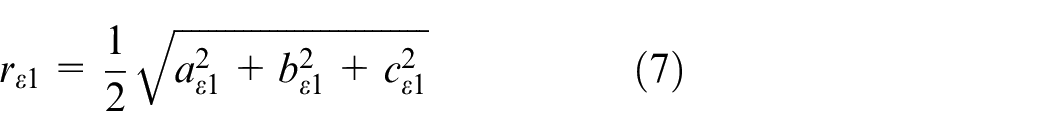
Similarly, bε2, cε3 can be obtained. Then the center ⊙ε1 (xo1, yo1) and radius rε1 of circle ⊙ε1 can be obtained.
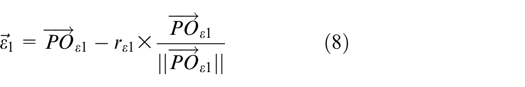
Combining equations (6) and (7), the vector expression of the distance from the actual position point P to the circle ⊙ε1 is obtained
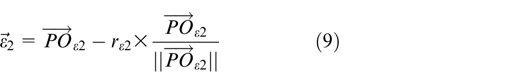
In the same way, the vector expression of the distance from the point P to the circle ⊙ε2 is
The two contour error vectors

This contour error calculation model takes full account of the interpolation point information with higher accuracy, when
Improved PSO algorithm to optimize fuzzy PID cross-coupled controller
Variable gain fuzzy cross-coupled control strategy
In actual machining, the existence of contour error will affect the machining accuracy of parts. In order to directly control the contour error and input a certain amount of compensation to each driving shaft to improve the coupling degree between each shaft, Koren et al. 10 proposed the idea of cross-coupled control and the control structure diagram is shown in Figure 3. The control quantity of a single servo drive system depends on its output and the output of other drive shafts. The correction signal generated by the cross-coupled controller compensates for the estimated contour error in each axis, thus improving the contour tracking accuracy.
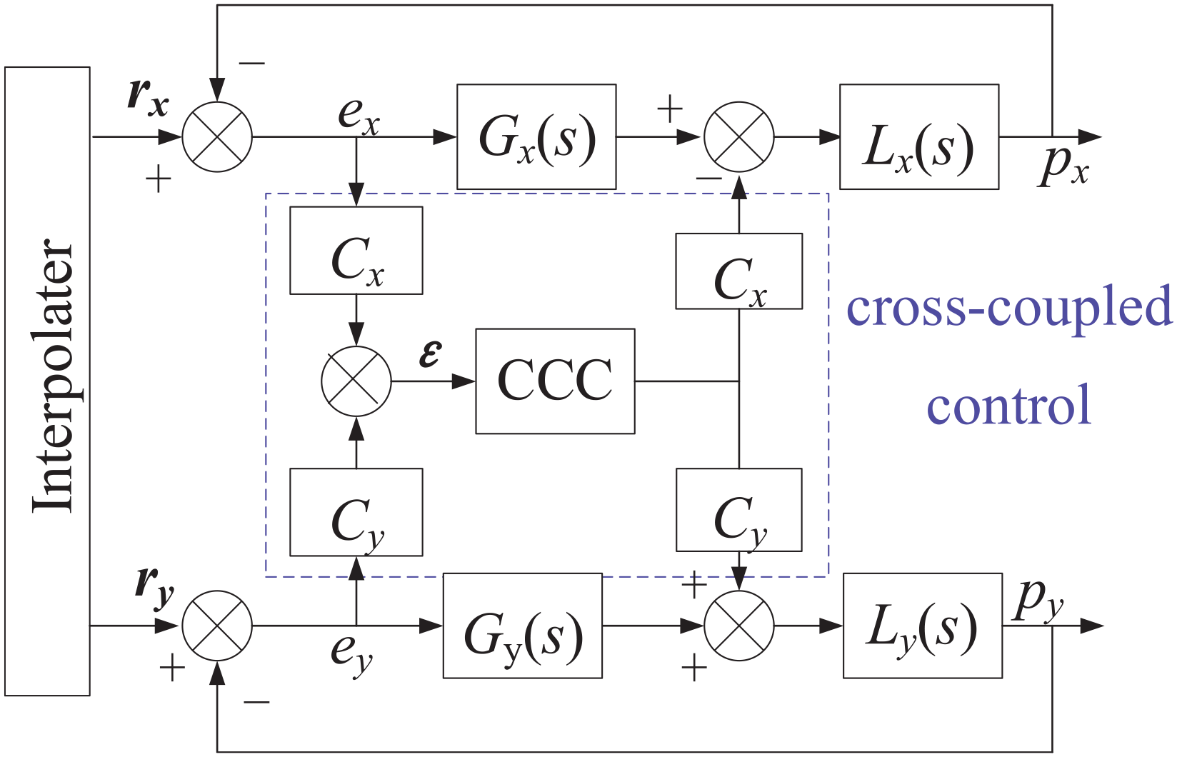
Two-axis cross coupled control structure diagram.
In the above Figure 3, r and r xy are the motion reference positions given by the interpolation, px and py are the actual positions after the x-axis and y-axis feed motions, respectively. e x and e y are the following errors of the x-axis and y-axis respectively. Gx, Gy is x-axis and y-axis position loop controllers. Lx and Ly are mathematical models of the controlled object in the x-axis and y-axis position loops, respectively. Cx and Cy are cross-coupled gains obtained by the contour estimation algorithm. ε is the contour error under the cross-coupled control structure. CCC is a cross-coupled controller. The contour error estimation algorithm in the previous section is applied to the above control structure and analyzed and verified in the subsequent simulation tests.
The traditional CCC controller is adjusted by PID control, and the parameter optimization of conventional PID control is mainly through theoretical calculation and engineering optimization. The parameters after theoretical calculation are not always directly usable. In this paper, a fuzzy controller is added to the PID adjustment, which can adaptively adjust the proportional, integral, and differential coefficients. A fuzzy cross-coupled controller is obtained by using a two-dimensional fuzzy controller, as shown in Figure 4. The contour error ε and the change rate of contour error Δε under the cross-coupled control structure are used as the input of the fuzzy controller. For the fuzzy processing, each input sample should be switched to the corresponding fuzzy set, that is, each input sample is multiplied by the corresponding factor, and the contour error quantization factors are defined as kε and kΔε respectively. The contour error ε and the change rate Δε are multiplied by the quantization factor to obtain the corresponding fuzzy domain, the fuzzy processing is completed. Return the actual position of the controlled object after the x-axis and y-axis feed through the mathematical model Lx and Ly of the position loop.
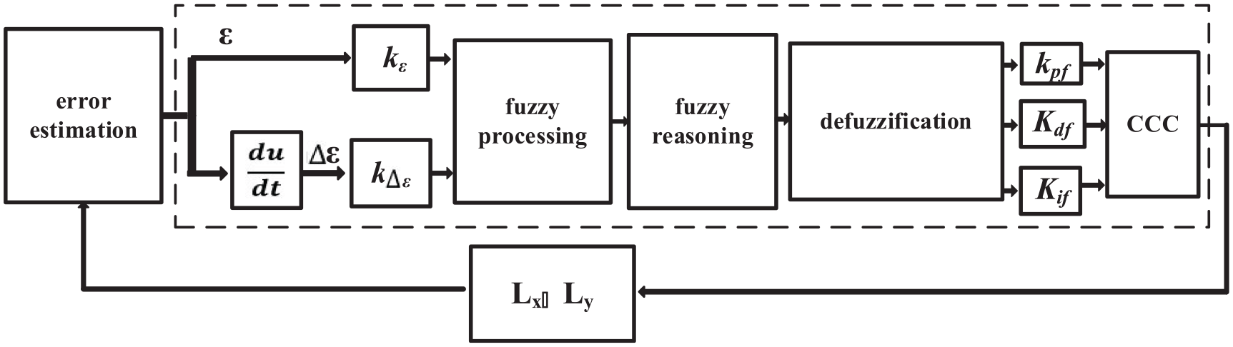
Fuzzy CCC control structure.
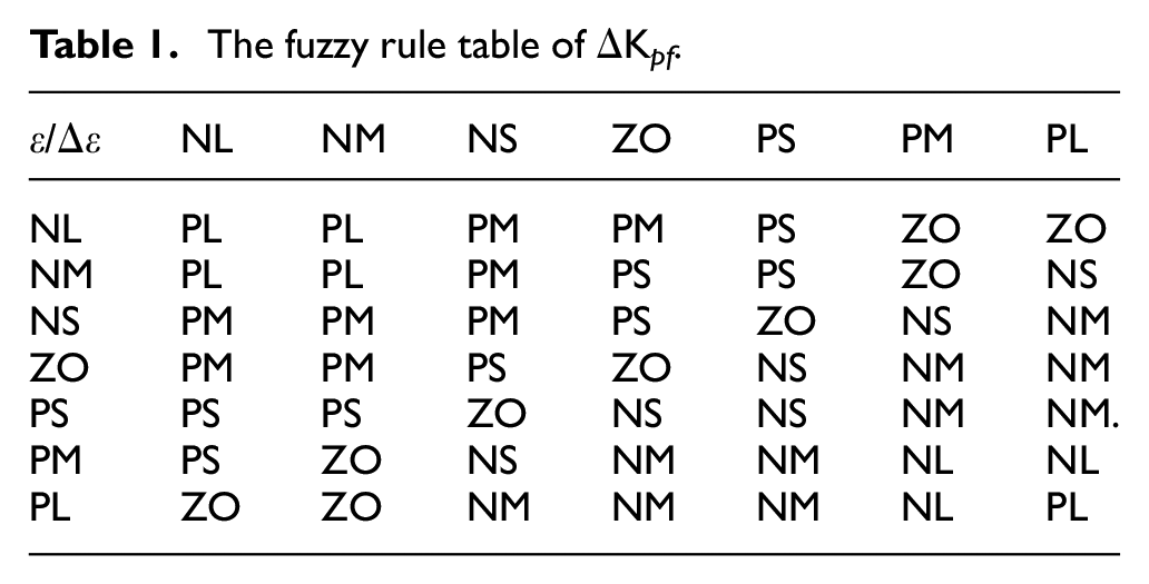
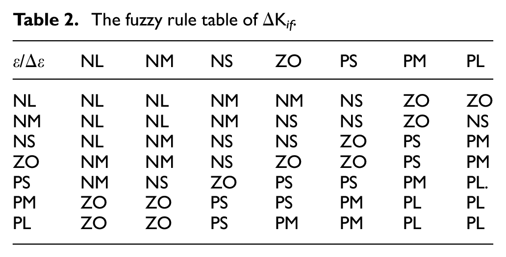
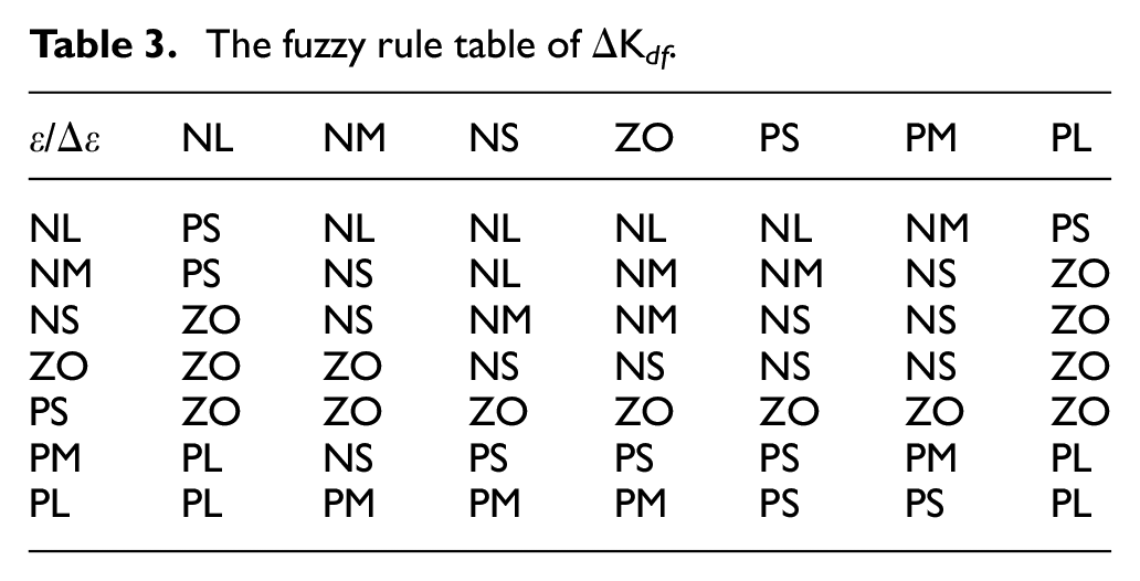
After the fuzzy processing, the fuzzy controller uses the set fuzzy rules to make corresponding decisions. After defuzzification, multiply by the proportional factors k pf , k if , and k df , the final output is the three adjustments of CCC, which are ΔKp, ΔKi, and ΔKd, the form of the fuzzy set is selected as “negative large (NL),”“negative medium (NM),”“negative small (NS),”“zero (ZO),”“positive small (PS),”“positive medium (PM),” and “positive Large (PL)” to describe the system’s variable. The fuzzy rules are obtained by summarizing the control experience and by fuzzy reasoning. The fuzzy inference mechanism will make inference decisions based on the established rule table. The fuzzy rules are given in Tables 1 to 3, corresponding to three output variables ΔKpf, ΔKif, and ΔKdf, respectively. Based on the established fuzzy rule table, Mamdani fuzzy inference is used to infer the fuzzy set of output. The defuzzification is performed using the center of gravity method. As shown in Figure 5, the output surfaces of ΔKpf, ΔKif, and ΔKdf are obtained after defuzzification, and the exact solutions ΔKpf, ΔKif, and ΔKdf of the three outputs in their respective fuzzy domains are multiplied by the corresponding proportional factors kpf, kif, and kdf. finally, the exact adjustment quantities ΔKpf, ΔKif, and ΔKdf are obtained. therefore, the control parameters of the fuzzy PID can be expressed as:
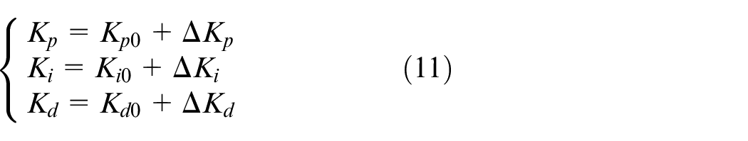
where Kp0, Ki0, and Kd0 are the initial values of proportional, integral and differential coefficients. ΔKp = kpf·ΔKpf, ΔKi = kif·ΔKif, ΔKd = kdf ·ΔKdf.
The fuzzy rule table of ΔKpf.
The fuzzy rule table of ΔK if .
The fuzzy rule table of ΔK df .
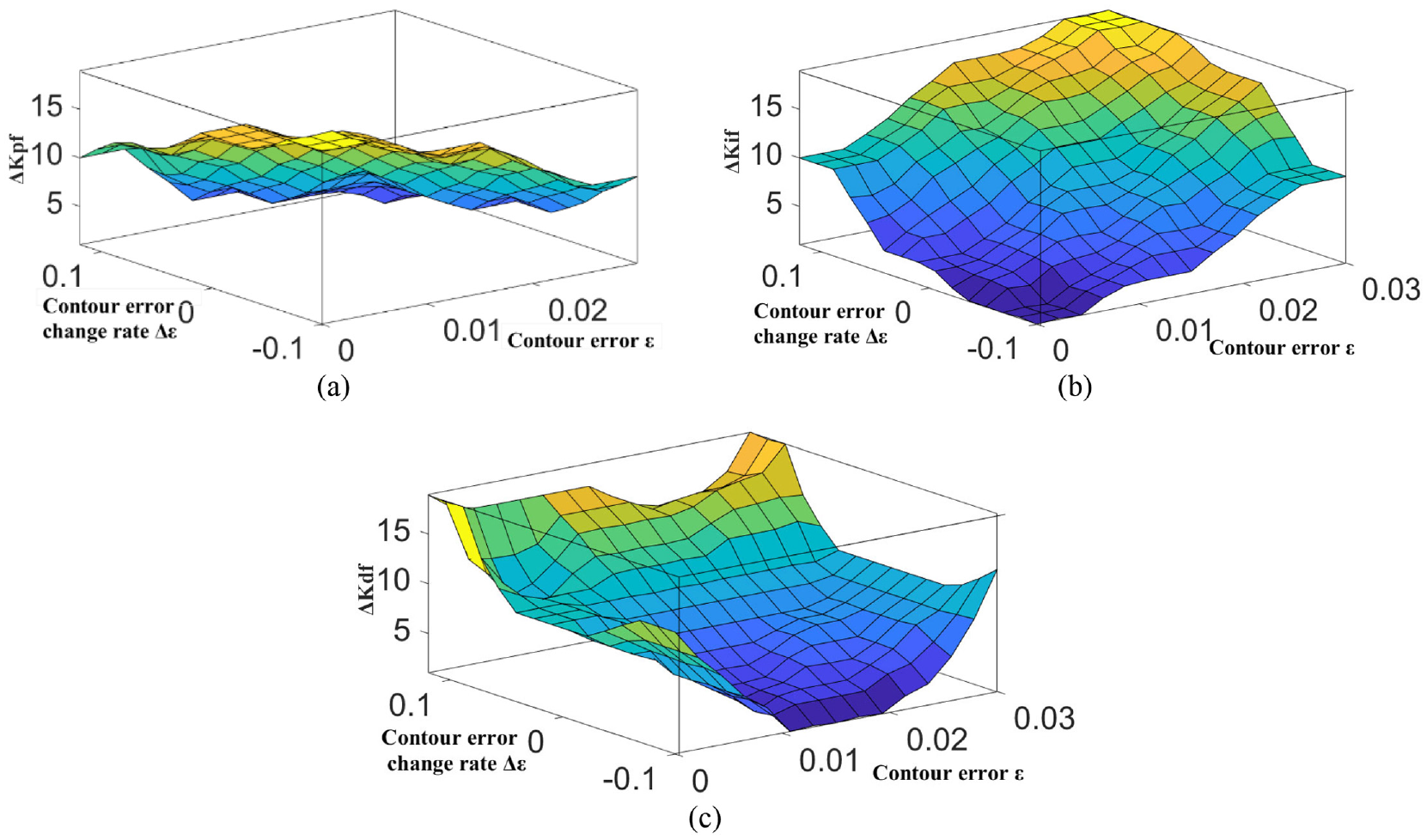
ΔKpf, ΔKif, ΔKdf output surface: (a) ΔK pf output surface, (b) ΔK if output surface, and (c) ΔK df output surface.
The control quality of a fuzzy controller depends mainly on the values of the quantization and scaling factors. A global optimization algorithm with high precision and fast convergence is needed to optimize the control parameters to improve the traditional fuzzy CCC. Therefore, an improved PSO algorithm for parameter optimization is proposed.
Traditional PSO algorithm
The basic idea of the swarm control algorithm is constructed by simulating the behavior of natural biological groups. Particle swarm optimization (PSO) is a swarm-based optimization technology based on swarm intelligence, which was first introduced by Dr. Eberhart and Kennedy in 1995. The inspiration comes from the foraging behavior of a flock of birds. As a global optimization evolutionary algorithm, PSO is used to solve optimization problems. The algorithm initializes a set of random particles with parameters to perform iterative computations. In each iteration, the velocity and position of each particle are updated by following the individual optimal position and the global optimal position of the particle, and the optimal solution satisfying the termination condition is finally obtained.25,26
The update formula of the velocity vid and position xid of the ith particle in the d-dimensional space in the standard PSO algorithm is expressed as:
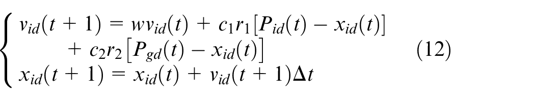
where, w is the inertia factor. c1 and c2 are learning factors. r1 and r2 are random numbers in (0,1). Δt is the step length, generally taking 1. Pid is the individual optimal position, Pgd is the global optimal position. i = 1, 2, … m, m is the population size. t is the number of iterations, t = 1, 2, …T, T is the maximum number of iterations.
Improved PSO algorithm
In the optimization process of the standard PSO algorithm, the global search ability will continue to weaken as the inertia factor w decreases, but the local search ability will continue to increase. The particles tend to fall into local optimization prematurely, affecting the global search ability and failing to balance the contradiction between global search and local search. The algorithm cannot be well coordinated due to the adjustment of inertia weights and the independence of learning factors. Therefore, an improved particle swarm optimization algorithm is proposed in this paper, which adjusts the learning factors by inertia weights. The method is based on the nonlinear decreasing strategy of inertia weights, and establishes the nonlinear change relationship between the learning factor and inertia weights. The global search ability and local search ability of the PSO algorithm are also better balanced when the two coordinates are changed. The calculation formula of inertia weight nonlinear decreasing strategy is:
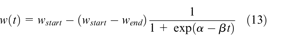
where wstart = 0.9; wend = 0.4; α = 3.4; β = 0.07.
The nonlinear change strategy formula of learning factor with inertia weight is:
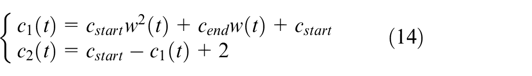
where cstart = 0.5; cend = 1.
Figure 6 shows the nonlinear variation curves of the inertia weights and learning factors, and it can be seen that the inertia weights establish a nonlinear relationship with the learning factors. Because large c1 values and small c2 are maintained, the global search capability of the improved PSO algorithm is enhanced in the initial stage of execution. In the later iterations of the algorithm, the situation is just the opposite, making our birds neither concentrated nor dispersed. Smaller c1 values and larger c2 values are taken to improve the local search accuracy and avoid premature convergence.
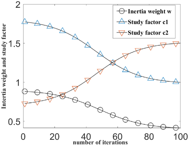
Curve of inertia weight and learning factor.
Adaptive fuzzy PID cross-coupled control based on improved PSO algorithm
The control effect of the cross-coupled controller is largely dependent on the selection of quantization factors kε, kΔε, and the proportional factors kpf, kif, and kdf. Therefore, to realize the adaptive fuzzy cross-coupled control of contour error, the quantization factors kε, kΔε, and the proportional factors kpf, kif, and kdf in the fuzzy controller are optimized by the improved PSO algorithm in this paper, to achieve the purpose of parameter self-optimizing and the best control effect. The specific process is as follows:
(1) Expected input value of the feed shaft. The interpolation point of the curve is taken as the expected input of each feed shaft.
(2) Calculate the input of the cross-coupled controller. The input of CCC is the contour error.
(3) Based on the improved PSO algorithm, the quantization factors kε, kΔε, and proportional factors kpf, kif, kdf of fuzzy CCC are optimized. The specific steps are as follows:
(a) Initialize the PSO algorithm parameters. The parameters of equations (13) and (14): wstart = 0.9, wend = 0.4, cstart = 0.5, cend = 1, α and β take values 3.4 and 0.07, respectively. The population size m = 50, the maximum number of iterations T = 100, and the parameter dimension D = 5. Determine the initial values of the quantization factor and proportional factor according to the trial-and-error method, and initialize the particle swarm.
(b) Update particle velocity and position. Calculation of velocity and position of next generation particles based on equation (12).
(c) The fitness value of particles is calculated, and the expression is:
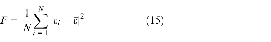
where N is the sampling point. εi is the contour error modulus at position i.
(d) Calculate the fitness value of each particle and determine whether to continue iteration. If the calculation of equation (15) reaches the expected value or the iteration has reached the maximum number of iterations, the iteration is terminated; otherwise, let t = t+1, and go to step as (b).
(4) According to step (3), the optimized quantization factor and proportional factor are obtained, and the optimal PID control parameters are calculated by combining equation (11). Therefore, The CCC control output is decoupled to each feed axis, as the control input of each feed axis for adjustment, and finally the contour error is formed into a coupling control. The contour control chart of parameter optimization is shown in Figure 7.
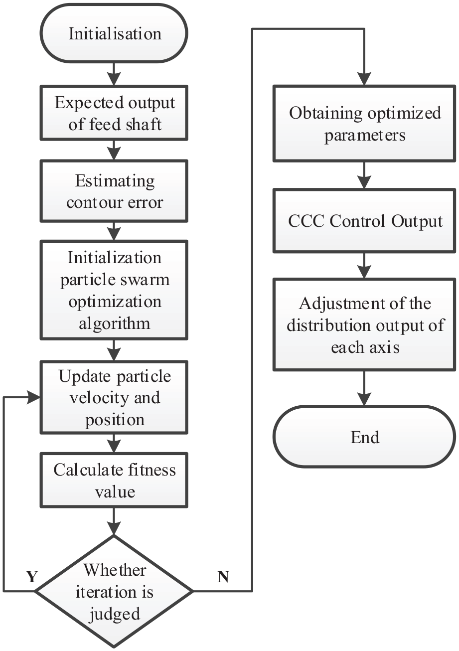
Contour control chart of parameter optimization.
Simulation verification
Based on the single-axis servo system model, 27 an x-y-axis servo system was built for analysis. The parameters for the x and y axes are as follows: torque coefficient CT = 0.57 N/A, Viscous friction coefficient B = 1.2 N·m·s, moment of inertia J = 0.015 N·m. The cross-coupled control simulation model is built in MATLAB/Simulink as shown in Figure 8.
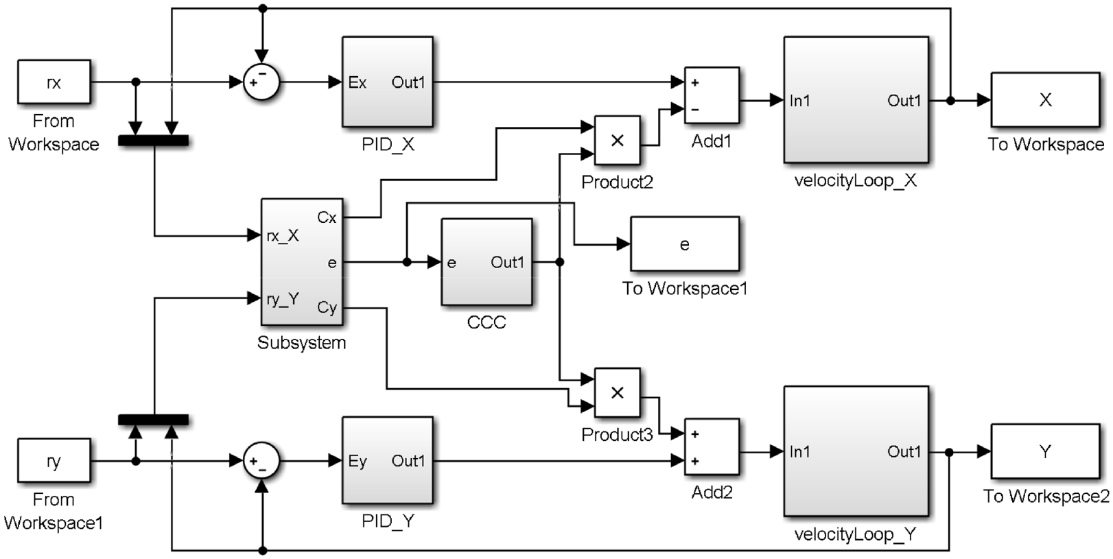
Simulation model of x-y axis servo system.
Circular trajectory simulation
The circular trajectory as shown in Figure 9 is used to test the contour error control performance, where the x and y-axis position input signals are:
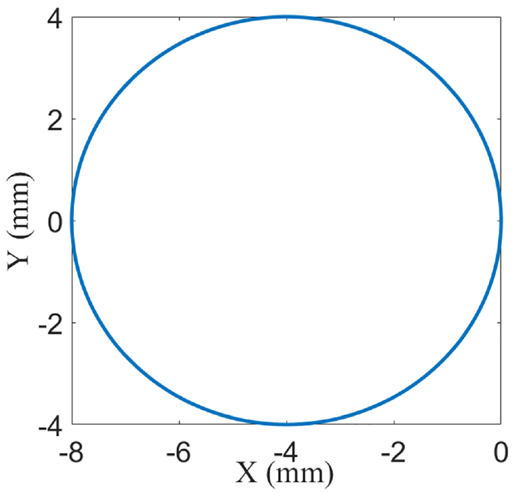
Circular trajectory.
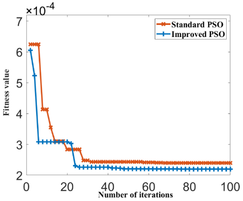
Difference PSO Fitness curve for circular trajectory.
It can be seen from Figure 10 that both the standard PSO algorithm and the improved PSO algorithm curves flatten out at the end, but the improved PSO algorithm has fewer iterations and smaller fitness. This indicates that the improved PSO algorithm is superior to the standard PSO algorithm in optimizing the quantization factor and proportional factor.
The improved PSO algorithm is used to optimize the parameters, and the optimal parameters (kε, kΔε, kpf, kif, kdf) = (1, 1.2, 87, 8.5, 4) are obtained. The contour error is calculated by the contour error calculation method of arc trajectory, and the control performance of contour error is verified based on the simulation of optimal parameters. As shown in Figure 11, the contour errors under no cross-coupled control, traditional fuzzy PID cross-coupled control, and fuzzy PID cross-coupled control of improved PSO are compared.
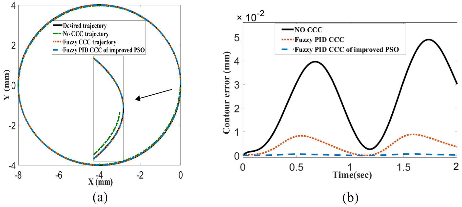
Comparison of the contour error control results for circular trajectory: (a) comparison of tracking effects of each method and (b) comparison of contour error of each method.
It can be seen from Figure 11(a) that the arc trajectory deviation is obvious without cross-coupled control. According to the comparison of Figure 11(b), it can be seen that the maximum contour error values under the non-cross-coupled control and the traditional fuzzy PID cross-coupled control are 0.049and 0.0089 mm, respectively, while the maximum contour error under the improved PSO fuzzy PID cross-coupled control is 0.00059 mm. The improved PSO algorithm optimize the cross-coupled control method of fuzzy PID, which can obtain higher contour accuracy and better contour control effect.
Typical “∞” trajectory simulation
Using the “∞” shaped NURBS curve trajectory shown in Figure 12 as the test object, the improved PSO algorithm is used to optimize the fuzzy PID control parameters. Figure 13 shows the fitness change curve of the standard PSO and the improved PSO algorithm.
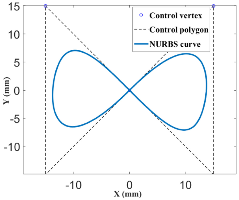
∞-shape NURBS curve.
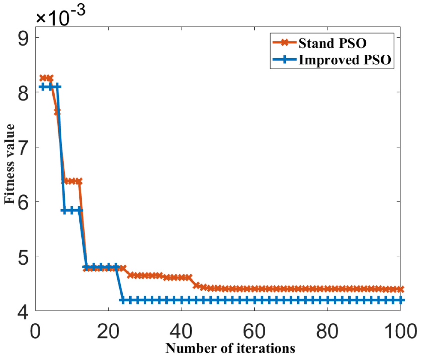
Fitness curve of standard PSO and improved PSO.
As can be seen from Figure 13, the fitness curves of both eventually flatten out, and the optimization effect of the improved PSO algorithm on the control parameters is better than the standard PSO algorithm. At the same time, the improved PSO algorithm has fast convergence speed and smaller fitness.
The estimation accuracy of “∞” NURBS curve is tested by the contour error estimation method in this paper. The actual contour error is obtained by offline calculation of the actual position of the trajectory collected by each axis according to the definition. 28 Among them, Figure 14(a) shows the estimated value of the “∞” shaped trajectory contour error, and Figure 14(b) shows the estimated deviation of the contour error. It can be seen from the Figure 7 that the estimated deviation value of contour error is less than 0.0184 mm, and the average value of estimated contour error is 0.0057 mm. This contour error estimation method has high estimation accuracy.
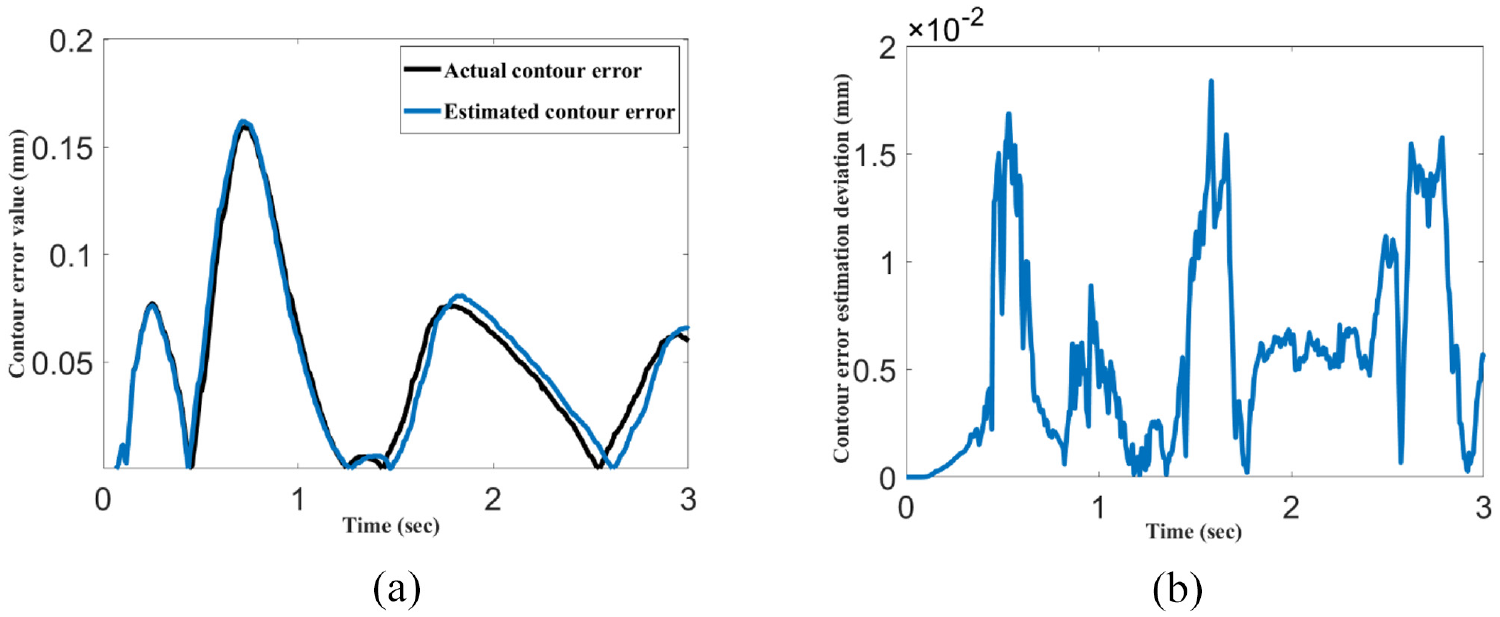
Results of contour error estimation for ∞-shape curve: (a) comparison of actual and estimated contour errors and (b) estimation deviation of contour error.
Comparison of no cross-coupled control, fuzzy PID cross coupled control effect, the results are shown in Figure 15.
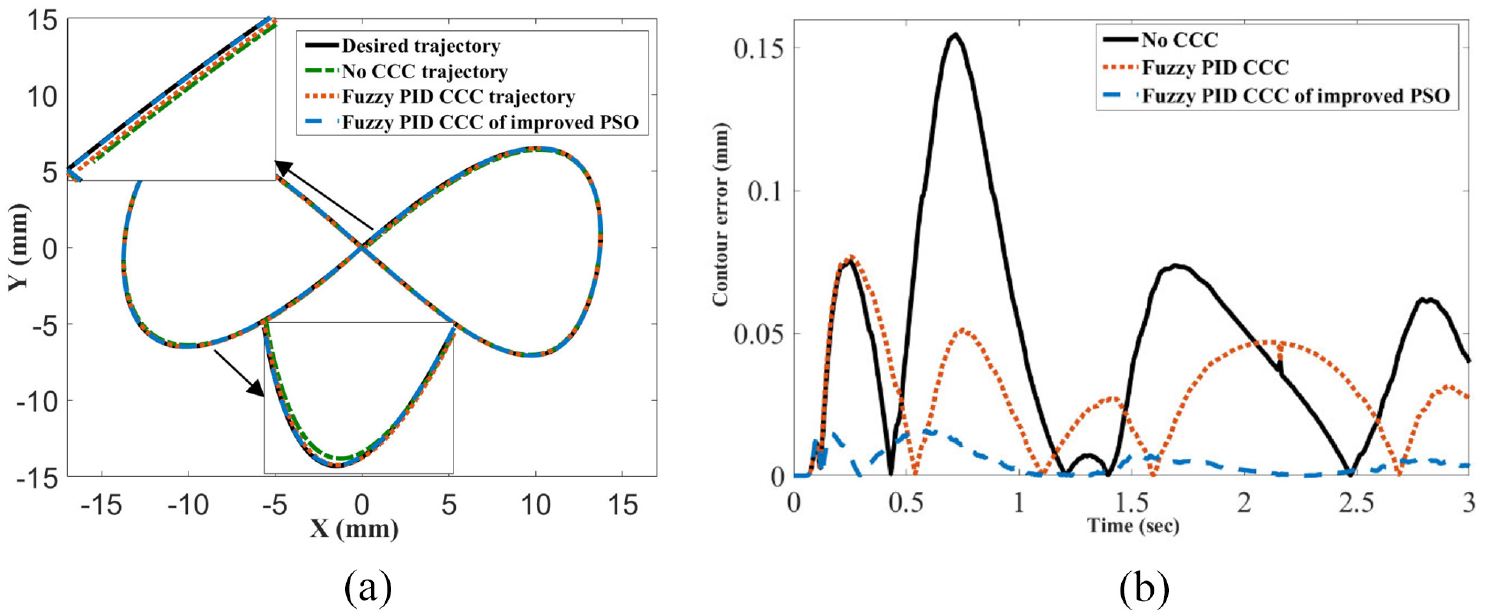
Comparison of the contour error control results for ∞-shape curve: (a) comparison of tracking effect of each method and (b) comparison of contour error of each method.
From the experimental results, it can be seen that the fuzzy PID cross-coupled control method under the improved PSO algorithm is better than the traditional fuzzy PID cross-coupled control method in controlling the contour error. Based on the control results of each method, the maximum MAX and the module average CEA of the “∞” trajectory contour error are calculated and compared in Table 4, where
Comparison of different contouring control methods for ∞-shape curve.
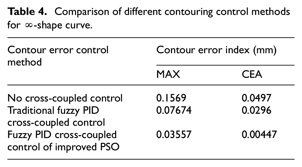
The results of the simulated “∞” curve are shown in Table 4, it can be seen that the maximum contour error under the fuzzy PID cross-coupled control of the improved PSO and the traditional fuzzy PID cross-coupled control are reduced by 77.33% and 51.09%, respectively, compared with the maximum contour error under the non-cross-coupled control. Compared with the conventional fuzzy PID-CCC control, the maximum contour error under the improved PSO algorithm control is reduced by 53.6%. The maximum contour error under the fuzzy PID cross-coupled control of the improved PSO algorithm is smaller than that under the traditional fuzzy PID cross-coupled control. At the same time, the average also reduced by 84.91%. It can be seen that the fuzzy PID cross-coupled controller of improved PSO has a better contour error control effect.
Verification of two-dimensional x-y axis experimental platform
Test experiments are carried out on the 2D X-Y axis experimental platform, to verify the proposed contour error control algorithm, which is based on fuzzy PID optimized by improved PSO. The experimental platform is an x-y axis platform motion control system with a motion control board as the core controller. The motion control system consists of upper computer system, servo drive control system, and mechanical drive part. The physical device diagram of the two-dimensional x-y axis experimental platform is shown in Figure 16, which is mainly composed of two-axis motion control card, servo driver and motor, grating digital encoder, and x-y mechanical motion platform. It can be seen from the figure that in the process of motion control of the experimental platform, the host computer generates the processing data of the target trajectory and transmits it to the motion control card. The motion control card generates the control instructions for the interpolation trajectory of each feed axis according to the instructions of the host computer and transmits them to each feed axis. Each axis moves the trajectory according to the control instruction and saves the encoder results back to the host computer.
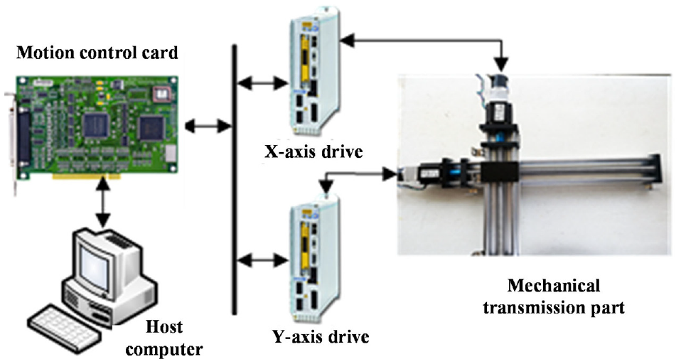
Two-dimensional x-y axis experimental platform.
A standard circular trajectory is used as an example to illustrate the effectiveness of the proposed contour error control method. Given the radius of the desired circle is 10 mm, where x = 10cos (πt) -10, y = 10sin (πt), the servo system moves according to the given instructions and uses the encoder to collect the actual position information of each axis to calculate the actual contour error value of the x and y-axis trajectory. The contour error control effects under no cross-coupled control, traditional fuzzy PID cross-coupled control, and fuzzy PID cross-coupled control of improved PSO are compared, and the comparison is shown in Figure 17.
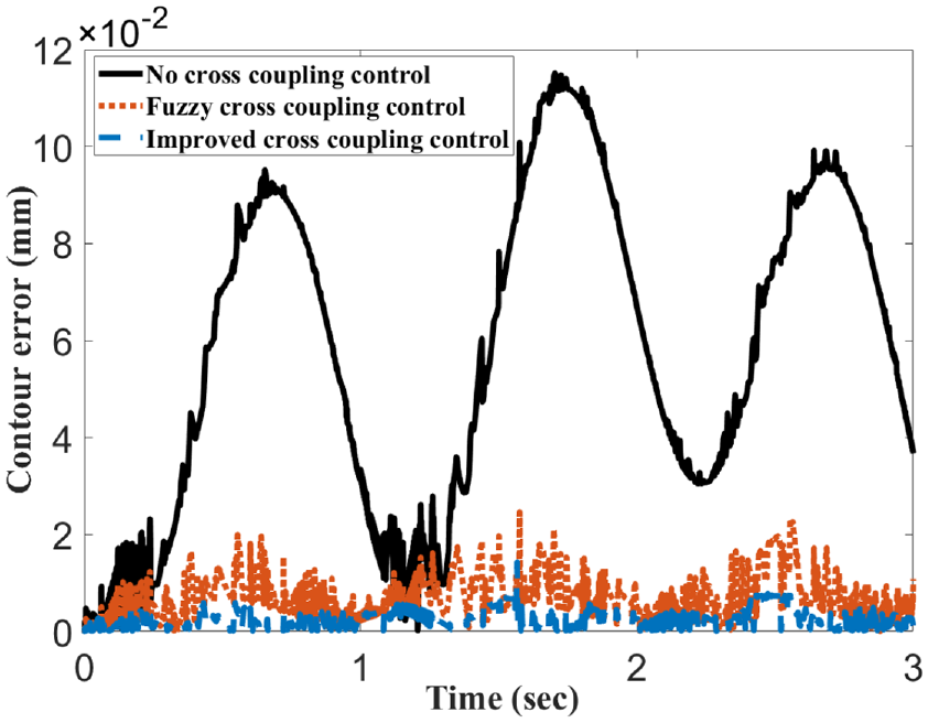
Comparison of control effects of various methods for contour error of circular trajectory.
It can be seen from Figure 17 that the maximum contour error under no cross-coupled control is 0.115 mm, and the maximum contour error under traditional fuzzy PID cross-coupled and fuzzy PID cross-coupled control of improved PSO is 0.0247 and 0.0143 mm. Compared with no cross-coupled control, the traditional fuzzy PID cross-coupled control method can reduce the maximum contour error by 78.57%, while the fuzzy PID cross-coupled control of improved PSO method can reduce the maximum contour error by 87.57%, and the average contour error is also reduced by 62.94% compared with the traditional fuzzy PID cross-coupled control method. Therefore, the fuzzy PID cross-coupled control of the improved PSO method has a better contour error control effect.
In order to enhance the convincing power of the proposed contour error control method, the NURBS curve is selected for experiments. The selected NURBS curve is shown in Figure 18. The test shows that the curvature of the curve changes irregularly.
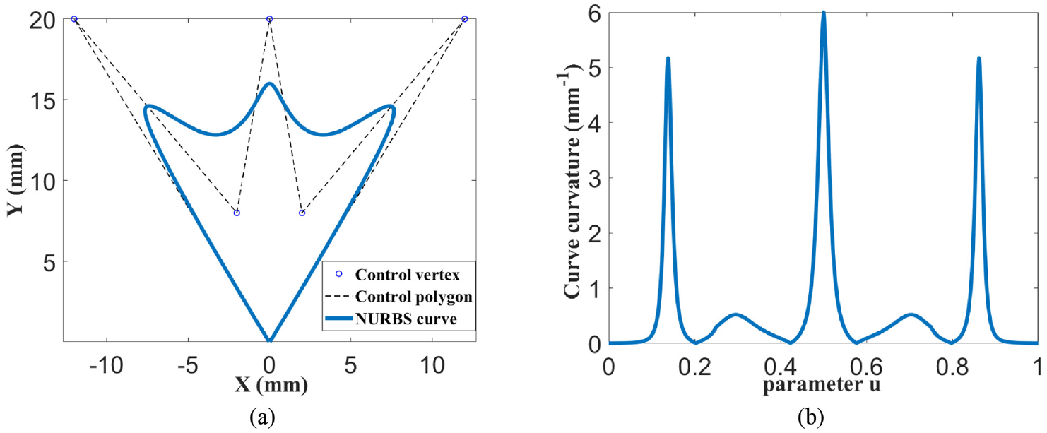
NURBS curve details: (a) trinomial NURBS curve and (b) NURBS curve curvature.
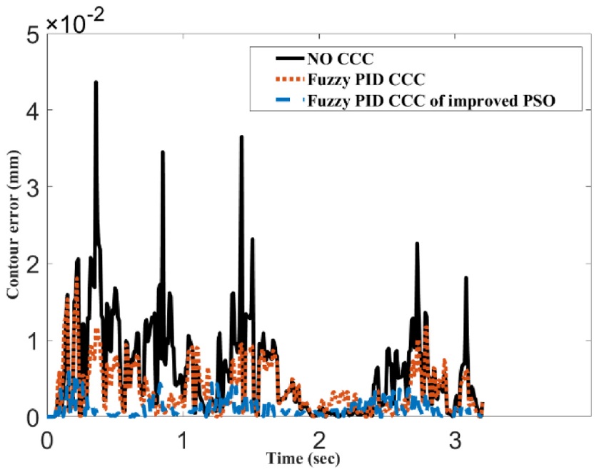
The proposed curve estimation deviation algorithm is used to calculate the trigonometric curve, and the result is shown in Figure 19. The contour error control effect of fuzzy PID optimized by improved PSO algorithm is tested. The actual contour error is calculated from the actual position of each axis collected by the encoder. The contour error control effect of each method is shown in Figure 20. The maximum MAX and average CEA of contour error calculated from the control results of each method are summarized in Table 5.
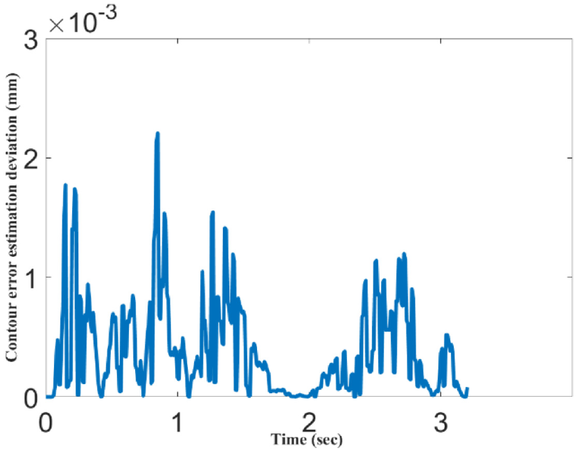
Deviation of contour error estimation for trident-shape curve.
Comparison of different contouring control methods for trident-shape curve.
Comparison of different contouring control effects for trident-shape curve.
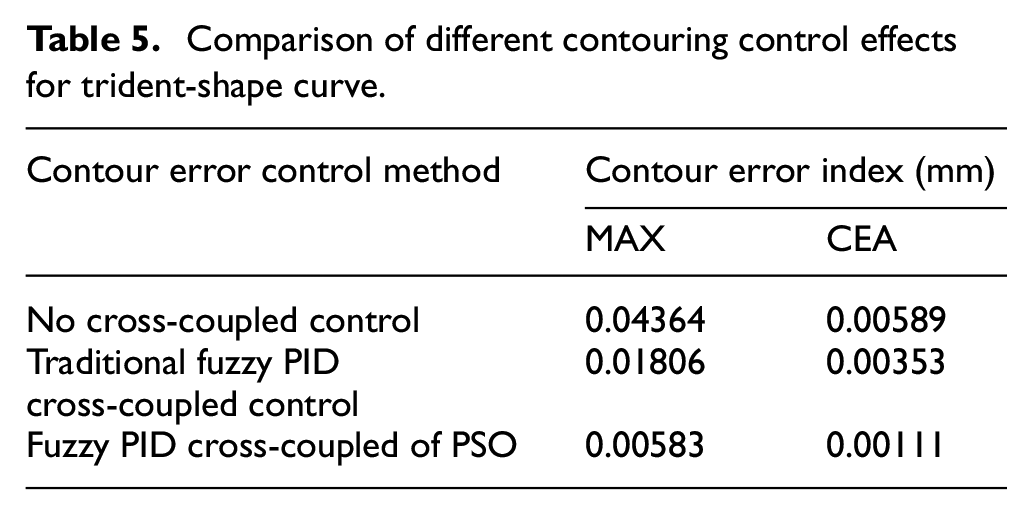
It can be seen from the graph that the estimation deviation of contour error is kept within 0.00221 mm, which indicates that the contour error estimation method has a high estimation accuracy. It can be seen from Figure 20 and Table 5 that the maximum contour error without cross-coupled control is 0.04364 mm, the maximum contour error under the traditional fuzzy PID cross-coupled control is 0.01806 mm, and the maximum contour error under the fuzzy PID cross-coupled control of improved PSO is 0.00583 mm, which is 86.63% and 67.7% lower than the previous two methods, and the average contour error module is 0.00111 mm. It can be seen that the contour error control effect of the proposed method is better than that of the traditional method, which also proves the effectiveness of the proposed method.
Conclusions
In this paper, based on the principle of approximate approximation of preferred points, the estimation algorithm of the free curve contour error under plane trajectory is studied to improve the estimation accuracy of the contour error. In the contour control, the control parameters of the fuzzy PID are optimized based on the improved PSO algorithm, and the cross-coupled control of the contour error with adaptive fuzzy PID is realized. The two-dimensional contour following is implemented on the experimental platform.
The contour error of the free curve is estimated based on the principle of approximate approximation of preferred points is designed, the simulation results of “∞” NURBS show that the estimation method in this paper can achieve a high-precision estimation of contour error. Aiming at the local and global search balance problem of the PSO algorithm, the learning factor of the improved PSO algorithm is adjusted with the inertia weight. The improved particle swarm algorithm is applied to the cross-coupled control model to optimize the system control parameters and achieve the suppression of the contour error. Compared with the traditional fuzzy PID cross-coupled control method, the fuzzy PID cross-coupled control based on the improved PSO algorithm can reduce the maximum contour error by 53.64%, which has better control effect. Therefore, the proposed improved particle swarm optimization algorithm has better optimization capability.
A fuzzy PID contour error control method, which is based on improved PSO optimization algorithm, is proposed to achieve high-precision contour following on arc contours and typical NURBS trajectories. The experimental results show that the proposed contour error control method applied to the arc contour following test has high following accuracy, and the contour error is controlled in the range of 0–0.0143 mm. In the typical NURBS trajectory test, the maximum contour error obtained by the proposed method is also reduced by 67.7% compared with the traditional Fuzzy PID control method, which meets the requirements of control accuracy, thus verifying the effectiveness of the proposed method.
It has potential of being integrated into application for other types of multiple axis tracking controller, in the future research, the authors will study more excellent contour control methods, and further apply them to three-axis and five-axis, considering relevant testing with CNC system manufacturers and conducting further research in this direction.
Footnotes
Declaration of conflicting interests
The author(s) declared no potential conflicts of interest with respect to the research, authorship, and/or publication of this article.
Funding
The author(s) disclosed receipt of the following financial support for the research, authorship, and/or publication of this article: This work was supported by National Natural Science Foundation of China [Grant Nos. 61703186 and 61973141]; Jiangsu Agriculture Science and Technology Innovation Fund [Grant No. CX(20)3059]; and A Project Funded by the Priority Academic Program Development of JiangSu Higher Education Institutions [Grant No. PAPD-2018-87].