
Abstract
Considering the variety of coupling errors and disturbances in multi-layer and multi-axis control systems, a novel control multi-layer and multi-axis strategy for structure is proposed in this article. First, the equivalent conversion of two models is proposed between master–slave mode and minimum adjacent coupling in multi-layer and multi-axis control model. Second, in view of existing synchronization control problem, this article presents master reference synchronous model and master–slave synchronous model in multi-layer and multi-axis synchronous control system. Moreover, an optimization control strategy based on combine cross coupling error control strategy is introduced. The stability and superiority of the proposed controller are theoretically analyzed. The combine cross coupling error experimental results demonstrate that interlayer starting synchronizing error maximum is 0.042 rad/s. Meanwhile, the startup and shutdown points of synchronizing error are 0.005 rad/s, the sync error tends to 0 between two points. The results show that the proposed strategy has a good tracking error and synchronizing error behavior.
Keywords
Introduction
Multi-axis centers play a key role in industrial fields to manufacture complex parts, such as impellers. In the machining of complex parts, synchronized multi-axis motions are required. Hence, the synchronous accuracy of translational and rotary axes is one of the important factors in the machines. Synchronous accuracy of rotary and translational axes has been investigated up to now.
Classical synchronous control theory is mainly proposed and developed by Y Koren 1 in the 1980s. The theory has three classes: the same ways (synchronized master command approach (SMCA)), master–slave mode (master–slave approach (MSA)), and the cross coupling control (CCC). Turl et al. 2 propose coupling compensation control strategy, which improves the synchronization performance, but for the motor coupling compensation control (n > 2), it always exists. 3 The scholars proposed the partial CCC.4,5 The existing synchronous control algorithm is mostly limited to two motors, which is difficult in expanding into the axis control.6–9
Wei et al.10,11 propose the problem of H∞ model approximation for a class of two-dimensional (2D) discrete-time Markovian jump linear systems with state-delays and imperfect mode information in 2015. The finite-frequency technique has the advantages of robust control, estimation, and fault detection. H Zhang and JM Wang12–14 propose the observer design problem for linear-parameter-varying systems with uncertain measurements on scheduling variables.
The existing control strategies are synchronization coefficient is 1 or the proportion for each motor speed, which does not involve nonlinear in multi-layer and multi-axis. For this problem, this article proposes a new combine cross coupling error control strategy of synchronous control thought and synchronous control algorithm, which is incorporated into combine ring coupling control through nonlinear synchronization coefficient in the controller. Combine cross coupling errors are defined to be differential system errors in multi-layer and multi-axis control model. Finally, the experiments verify the stability and superiority of multi-layer and multi-axis synchronous control algorithm. This article provides a new idea for analyzing multi-axis synchronous control and provides a method for analyzing complex multi-axis synchronous structures.
Change of model
When the input signal is only one signal in the multi-layer and multi-axis control model, the master–slave mode is minimum adjacent coupling in its essence. In the case of multi-layer and multi-axis, the two modes can be as the equivalent conversion between two modes in Figure 1. For different input signals, the two modes cannot be replaced between the minimum adjacent coupling and master–slave mode. The input signal of the minimum adjacent coupling model arises from the same signal; for master–slave mode, slave axis receives a given input signal from master axis, the input signal of third layer from output signal of the second layer in multi-layer and multi-axis system.

Multi-layer and multi-axis transformation diagrams.
Where M defines master axis, where S defines slave axis. Figure 1 shows three layers, each layer has three axes.
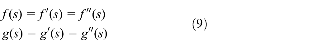
We can conclude that


In the relationship between the master axis
From equations (1)–(3), we obtain establish the relationship with master axis
A limitation of minimum adjacent coupling is that it is unable to realize the master–slave control, which is given in multi-layer and multi-axis model. It is easy to establish mathematic relationship between master axis and layer 1, or the other relationships between the layer 2 and layer 1 in Figure 1(a). If the second layer 2 directly establish the mathematical relationship is very complicated with the master axis. So the system model of multi-layer and multi-axis is meaningful, the existing research method is based on the synchronization coefficient of 1, and the requirements of each axis running situation has significant limitations. There is no master–slave relationship between minimum coupling, which could not run the nonlinear between layers5,15,16

For front layer of multi-layer multi-axis, the relationship between the position and the velocity is given as
For master–slave model, linear change is constant A, and if change relationship is nonlinear between master axis and slave axis, which defines
Combine cross coupling error synchronization control thought
According to different applications, 10,22,23 combine cross coupling error control strategy is in multi-layer and multi-axis system, and due to the existence of multi-layer operates in master–slave synchronization control method, the same layer axes are given the same control and error compensation control idea of loop coupling control mode. Synchronizing error will cause any motor speed change between the motor and the adjacent motor in ring coupling error control strategy. Compared to the input mode of signal, it is clear that all the electrical signals arise from one signal, and output signals are not the same.
This control strategy achieves consistent follow and axis coupling synchronizing error compensation for the same master axis signal, so the system is guaranteed in the process of starting performance and anti-jamming performance. For multi-layer and multi-axis complex system, this control strategy is a kind of ideal synchronization control strategy.8,16,17

Block diagram of master reference synchronous control system.
In this kind of control mode, all units of the system share an input signal, the same as the ring cross coupling error, and the reference signal input signal is the same. Each partition by a single-axis drive does not share the same motor output power. Each unit obtains consistent input signal, and each unit of the input signal is not affected by any other factors besides the reference signal, so the disturbance in any unit will not affect other units.8,18,19 The transfer function of first motor output angular velocity is derived as follows

The motor load torque transfer function is relative to the first motor (No. 1 axis)


The selected parameter values are the same
If the reference signal changes, the command reference control system can complete the synchronization

One obtains

Therefore, multi-axis master reference synchronous control system is the same tracking error with the same parameters

For the N-axis master reference control multi-axis synchronous control model, when a disturbance occurs on any ith axis, the synchronization between the other axes and the disturbance axis is the same, and there is no effect on the other axes in the control model.
In master reference control mode, Figure 3 shows that

Block diagram of master–slave synchronous control system block diagram.
The following performance and synchronization performance of the N-layer multi-axis synchronization control model can be derived as follows


The selected parameter values are the same

One obtains


The performance of the system following reduced with the increase in the number of layers

The ith layer load disturbances
During ith axis disturbance, the synchronization performance of axis is same from No. 1 axis to No. i − 1 axis, and equation is same. The synchronization performance of the system reduced with the increase in the number of layers.
As it can be seen by the above equations, synchronization performance of axis is the same axis which is relative to the N axis during N layer load disturbances.
Ring CCC strategy is considering each motor speed with a given speed in Figure 4, where

Block diagram of ring cross coupling structure.
Based on the tracking error and the definition of the synchronizing error, axis synchronous control problem can be described as follows: the design of controller and control of the torque make the speed tracking error
Combine cross coupling synchronizing control strategy: control axis torque of each layer should be able to stable convergence,21,24 which make this layer axis tracking error with upper layer of the synchronizing error, and two axes and the adjacent tree synchronizing error at the same time. The ith layer of control torque should be able to make the interlayer of i,
The combine cross coupling error method is proposed above in several ways. The single-layer multi-axis synchronous control system has advantage of synchronicity and following performance by ring cross coupling error control strategy. The multi-layer and multi-axis synchronous control system decreases the complexity of relationships with master axis by combine cross coupling error control strategy.
Combine cross coupling error control algorithm
Existing algorithms usually consider only the synchronization performance in the same layers, which do not analyze the synchronization of multi-layer and multi-axis. Combine cross coupling error synchronous control algorithm can be summarized as the following: defines the ith axis of the tracking error in multi-layer and multi-axis, each layer of the axis control considering the state of the adjacent two axis. For different applications, combine cross coupling error synchronous control algorithm has two advantages in Figure 5, one is ring cross coupling error in the same layer, which makes the synchronization between the axes, and the other is master–slave mode between layers, which maintains the synchronization with the master axis.

Block diagram of combine-cross-coupling error structure.
Where

The synchronization error in interlayers4,5

Equation (23) shows the ring cross coupling error in the same layer, where

where GS denotes transfer function, M is the master value, KM is offset master value, and KS is offset slave value. Equation (24) shows the nonlinear relationship between the slave axis and the master axis
Define
Define
Define GS is nonlinear coefficient,
Equation (24) shows the tracking error without synchronizing error, which is master–slave mode in multi-layers


where

where

So

where Λ is positive number,

Control function of arbitrary axis tracking error can be described in multi-layer and multi-axis


Substituting equation (32) to equation (33) yields

One obtains

The tracking error of combine cross coupling error control system depends on the tracking error of multi-layer synchronization.


When time tends to infinity, synchronizing error tends to 0. Define the control function of the ith axis as

where
The output of the controller design for each layer and each axis in a given input torque of interlayer.

where

In this article, combine cross coupling error control algorithm not only makes the system good dynamic performance and anti-interference but also makes the system faster response speed at the same time, which improves the synchronization precision of the system for requiring higher synchronous precision in multi-layer and multi-axis model.
The computation complexity of multi-layer and multi-axis synchronization control scheme can be in high precision and high-speed machining, which effectively implements synchronous precision.
The advantages of multi-layer and multi-axis synchronization control scheme provide methods for analyzing complex topological multi-axis structures. The control scheme will provide a meaningful analysis basis for the motion control system of multi-layer complex structure and quantify the digital relationship between the layer and the axis of the system, which broadens the multi-axis motion control analysis.
The simulation parameters synchronous comparative analysis
In the process of multi-layer and multi-axis system, resistance mutations are changing, and the motor output axis torque must also adjust accordingly, to maintain the stability of the movement. Therefore, load disturbance is an important factor that affects synchronization performance of the system.
Based on the above model in Figure 5, the article uses MATLAB/Simulink platform to build a system simulation model.25–27 Here, torque constant Kt = 2.2 N m/A, back electromotive force coefficient Ke = 0.33, stator resistance R = 0.53Ω, stator inductance L = 8.7 mH, current sensor feedback coefficient Kf = 0.57, current controller gain Kpi = 300, moment of inertia J = 0.0045 kg m2, peak current Imax = 46 A.
The master axis speed is set to 1 rad/s. The method was further tested by adding a force disturbance to axis M0 and axis S11 from 25 to 35 s during the motion, which makes it deviate from the reference speed.5,8Figure 6 shows the combine cross coupling error structure in multi-layer and multi-axis synchronized control model. System is the action of uniform motion with unit step signal. The simulation results are shown in Figures 6–8. The tracking error and synchronizing error curves without disturbance are shown in Figure 6. The tracking error and synchronizing error curves with axis M0 disturbance are shown in Figure 7. The tracking error and synchronizing error curves with axis S11 disturbance are shown in Figure 8.

(a) Axis M0, axis S11, axis S21, and axis S31 tracking error curve without disturbance, (b) synchronizing error curve between axis M0 and axis S11, (c) synchronizing error curve between axis M0 and axis S21, and (d) synchronizing error curve between axis M0 and axis S31.

(a) Axis M0, axis S11, axis S21, and axis S31 tracking error curve with axis M0 disturbance, (b) synchronizing error curves between axis M0 and axis S11, (c) synchronizing error curves between axis M0 and axis S21, and (d) synchronizing error curves between axis M0 and axis S31.

(a) Axis M0, axis S11, axis S21, and axis S31 tracking error curve with axis S11 disturbance, (b) tracking error local curve, (c) synchronizing error curves between axis M0 and axis S11, (d) synchronizing error curves between axis M0 and axis S21, and (e) synchronizing error curves between axis M0 and axis S31.
Experimental results
In the process of start, the system of the tracking error converges to 0 quickly, interlayer starting maximum synchronizing error is 0.042 rad/s in Figure 6, the maximum starting synchronous control accuracy is 4.2%, the maximum synchronous error is 0.001 rad/s in steady state, synchronous control accuracy is close to 0, which can achieve high-speed synchronization control system of the performance index requirements.
Figures 7 and 8 show that the system tracking error and synchronizing error response in load mutation (25–35 s). When axis M0 disturbed, interlayer tracking error and starting maximum synchronizing error are 0.05 rad/s and the starting maximum synchronous control accuracy is 5% in Figure 7. In the case of a disturbance, the startup and shutdown points of maximum synchronizing error are 0.12 rad/s, the sync error converges to 0 between two points.
Under the first-layer axis perturbation, the startup and shutdown points of synchronizing error is 0.005 rad/s, the sync error converges to 0 in Figure 8.
For multi-layer and multi-axis synchronous control model, it can be seen that the synchronizing error increases with the number of layers, the synchronizing error become main problems interlayer in interlayer synchronizing error, which proves the rationality of the type (30) and (31).
The results show that the method is less tracking error and synchronizing error, which effectively restrains the load mutation and the influence of parameter perturbation. The synchronicity of combine cross coupling error effectively achieves the requirements of high-precision synchronous control system performance index.
Conclusion
A novel control multi-layer and multi-axis strategy for structure is proposed in this article. Synchronization control strategy of combine cross coupling error is produced. Combine cross coupling error control strategy is proposed in multi-layer and multi-axis system, and the motor synchronous error is low. The axis load disturbance occurs, system synchronization error is effectively suppressed, axis disturbance has little impact on synchronization performance, and the dynamic synchronization performance is better than using minimum adjacent coupling control strategy. The simulation experimental results demonstrate that interlayer starting maximum synchronizing error is 0.042 rad/s; meanwhile, the startup and shutdown points of synchronizing error is 0.005 rad/s, and the sync error tends to 0 between two points. It is inherently capable of maintaining synchronization between the axes during startup and shutdown and even during extreme or abnormal load conditions. Simulation experimental results verify the effectiveness of the proposed approaches.
The research of complex multi-layer and multi-axis model will be in the direction of development.28,29 For multi-layer multi-axis system, the local stability characteristics of the analysis will be of meaningful research. In the future research, we will employ convex optimization algorithms to improve multi-layer and multi-axis model.30,31
Footnotes
Academic Editor: Hamid Reza Karimi
Declaration of conflicting interests
The author(s) declared no potential conflicts of interest with respect to the research, authorship, and/or publication of this article.
Funding
The author(s) disclosed receipt of the following financial support for the research, authorship, and/or publication of this article: This work was supported by Anhui Provincial Natural Science Foundation of China (grant no. 1608085ME106) and Natural Science Foundation of the Anhui Higher Education Institutions of China (grant no. KJ2015A063).