
Abstract
The immediate measurement of dynamic flow rate is of importance in the modern hydraulic system. Following a brief review and analysis on measuring methods of dynamic flow rate, authors introduced the structure and working principle of a two-dimensional piston dynamic flowmeter. Consequently, a mathematical model was carefully established based on its unique mechanical properties due to the two degrees of working freedom. Meanwhile, the transform function is obtained to describe the dynamic characteristics and used to discuss influences from various design parameters. Finally, a 3D printed prototype was designed and fabricated to measure the sinusoidal flow rate with the frequency range of 1–7 Hz on a calibration test rig. The discrepancy between the experimental and the simulated date is quite foreseeable considering the major influence of low oil bulk modulus due to air bubbles. Although the magnitude reaches −3 dB at 4 Hz, the dynamic characteristics are acceptable and can verify the feasibility of applying the two-dimensional piston flowmeter on the dynamic measurement field. The shortcomings of this prototype are well discussed in the conclusion part to provide guidance to enhance the design ability of next-generation prototypes.
Introduction
The immediate measurement of dynamic flow rate increasingly plays a critical role in modern hydraulic systems, especially in those systems that require instantaneous flow rate feedback like servo-controlled fuel supply system in aircrafts,1,2 or in those demand high accuracy flow rate control such as the lifting system to control aircraft landing gear, 3 and also in those desire to monitor the high frequency flow ripples at the outlet of the piston pump in the hydrostatic circle. 4 Unlike the positive displacement flowmeter, as a mature instrument, is widely applied for the measurement of steady flow rate because of its high accuracy and insensitivity to fluid medium, usual measuring methods for the dynamic flow rate in hydraulic system are still facing their own challenges in industrial applications.5,6
Orifice flowmeter utilizes pressure sensors to monitor the pressure drop through specific orifices and indirectly calculates the passing flow rate through mathematical models. Recently, Shah et al. 7 and Singh and John Tharakan 8 started CFD based analysis on the orifice flowmeter with single orifice and multi-hole, respectively. Doblhoff-Dier et al. 9 proposed a mathematical model considering inertia and reverse flow and verified the applicability through experiments. Besides, displacement sensors could be introduced in the orifice flowmeter to measure the axial motion of cover blade caused by the flush from the flow. Lu and his team proposed a cartridge high pressure dynamic flowmeter, which using a thin blade with low inertia as the flow sensing element. 10 Although the orifice flowmeter has been developed for decades, its mathematical models can’t clearly describe the relationship between the measured parameter and the flow rate since the turbulence flow and vortex flow exists in the fluid field around the orifice.
Therefore, laminar flowmeter uses specific structure, that is, capillaries, to create a laminar flow and calculates the flow rate according to Hagen-Poiseuille equation. 11 Xiao-lu et al.’s 12 work shows that laminar flowmeters have better dynamic performance and accuracy in the face of step changes in fuel flow. Kagawa et al. applied the laminar flowmeter to the measurement of gas volume flow and reaches 50 Hz as its dynamic response frequency.13,14 However, limited by the structure of the laminar flow element, the laminar flowmeters inevitably produce a large pressure difference during the measurement process and only applied in the measurement of low-viscosity fluids such as gas and fuel.
The servo/dynamic cylinder is considered as another well-known method to obtain the dynamic flow rate. Due to the low inertia and low friction design, the servo/dynamic cylinder is initially introduced as the calibration component with a dynamic bandwidth 10 times that of the tested servo valve.15–17 However, the stroke of the piston limits its application to test the small amplitude oscillation flow. In order to improve the continuous measurement capability of the dynamic cylinder, Liu et al. 18 proposed a pump-cylinder composite structure flowmeter which measures the high-frequency oscillation flow by the dynamic cylinder and simultaneously monitors the steady-state flow by the metering pump. The speed of the metering pump is controlled through a feedback system to guarantee the position of the dynamic piston of the cylinder is at the mid of stroke.
The attempts to applying traditional rotor flowmeters into the field of measuring dynamic flow rate is mainly focus on enhancing the secondary instruments and developing soft measuring algorithms. Yuan and Zhang 19 established the dynamic models of the turbine flowmeter and obtained 4.61 Hz calibrated bandwidth through experiments. Li et al. 20 proposed a scheme to use the average value method and the parabolic method to carry out the data reconstruction in order to improve the dynamic characteristics of gear flowmeters, and the experimental results verified his conclusion. Zhang 21 proposed a third planet gear flowmeter with special low inertia structure design to reach 25 Hz response frequency when measuring a sinusoidal pulsating flow.
The last major method for dynamic flow rate measurement is using mass flowmeters. Coriolis flowmeter, as one of the most typical mass flowmeter, has good dynamic response performance because of the combination of metering components with high response frequency and effective computational algorithms.22,23 Due to the flow fluctuation and the vibration of pipeline, the Coriolis flowmeter demands an instantaneous filter to diminish the signal noise and improve the working stability.24,25 But the rigorous use and installation conditions of the Coriolis flowmeter limit its application in modern hydraulic systems.
The presented work emanated from the research achievements obtained by authors’ research group which is focused on two-dimensional (2D) hydraulic components.26–29 The “2D” concept implies allowing the critical parts of the designed hydraulic components to have two working degree of freedom. 30 Authors’ previous researches show a novel flowmeter using parallel 2D pistons as the metering units for the purpose of measuring the steady flow rate.30,31 The working principle of the former flowmeter involves simultaneously utilizing the rotational movement to distribute the flow rate and the reciprocation movement to form the displacement. Combining with the increasingly understanding depth of the 2D piston, authors believed that, when the Hall sensors are replaced by the displacement sensors, the 2D piston flowmeter could work as the servo/dynamic cylinder to have a high response frequency. And even better, the integrated structure of 2D piston could be fully utilized to realize the continue measurement of the dynamic flow rate.
In this work, a new 2D piston flowmeter is proposed for the aim of measuring the dynamic flow rate. After a brief introduction of structure and working principle, a transform function is presented by establishing the mathematical model and carried out simulation analysis of critical parameters to guide the design. Finally, a 3D printed prototype is fabricated and experiments are performed to estimate the dynamic characteristics of the flowmeter.
Structure and working principle
In this section, the most crucial contents of the structure and the working principle of the novel 2D piston flowmeter are demonstrated briefly so as to illustrate an unambiguous blueprint of this design. A more specific and understandable description was presented in the previous paper.30,31 The structure of the 2D piston flowmeter and its critical components are shown in Figure 1(a). The components (1)–(7) and (10)–(16) respectively constitute a left metering unit and a right metering unit, as shown in Figure 1(b) and (c). The left metering unit and the right metering unit are separated by a board (9). The active parts in left metering unit consist of piston (4), cone rollers (3, 6) and are referred to as the left piston set whereas piston (13), cone rollers (11, 14) consist the right piston set. Two piston sets are embraced by related sleeves (5, 12). A coupling (8) on board (9) firmly connects two piston sets in the circumferential direction and guarantee they still have independent axial motions. Two displacement sensors are installed to related rod ends of two piston sets, respectively. The two metering units are symmetrical to each other, but two piston sets have a 45° phase difference around the x-axis.

Architecture of the 2D piston flowmeter and its two metering units: (a) overview sight, (b) left metering unit, and (c) right metering unit. 1, 16. Displacement sensor; 2, 7, 10, 15. Cam track; 3, 6, 11, 14. Cone rollers; 4, 13. 2D piston; 5, Left sleeve; 8. Coupling; 9. Board; 12. Right sleeve. A. Inlet port; B. Outlet port; C, G, H, L. Displacement chamber; D, E, J, K. Window; F, I. Flow tunnel; a, b, c, d. Slot.
According to the similarity between the two metering units, the right one is highlighted to show more designs and introduce the working principle. As seen from Figure 1(c), four slots (c, d) have been evenly distributed on the piston (13) and alternately connected to two displacement chambers (H, L). Four windows (J, K) are also evenly and circumstantially arranged on right sleeve (12) and alternately connected to two fluid tunnels (F, I). Every two cone rollers (11 or 14) and the contacted cam track (10 or 15) constitutes a motion converting mechanism to transfer the piston’s reciprocation motion into rotation, or vice versa.
If the Figure 1 is assumed as the initial point, the connection alternation between displacement chambers and fluid tunnels is put forward in Figure 2 for one half rotation. When the displacement chamber (L) is flooded with the oil form the fluid tunnel (I), the piston (13) is driven toward its left end of stroke and rotated 45° under the help from motion converting mechanism. In this stage, the oil in displacement chamber (H) is pushed into the fluid tunnel (K). The yellow color indicates that two displacement chambers are disconnected with two fluid tunnels at this moment. Under the drive from the moment of inertia and the rotation of left piston set, it’s hereby worth to mention that two piston sets rotate simultaneously and incessantly, the right piston set rotates another 45° and meanwhile is forced to move toward its right end by the motion converting mechanism. Afterward, the half circle is completed and the stage of the right piston set is repeated from stage 1. Due to the design of 45° phase difference between two piston sets, the left piston set has a 45° advance comparing to the right piston set.

Working stages of right piston set in a motion period.
In the above working process, the oil pushes the 2D pistons (4, 13) to move axially to form a metering function. At the same time, the rotation of the 2D pistons (4, 13) will change the areas between the slots (a, b, c, d) and the windows (D, E, J, K). When measuring a steady flow, the displacement curves and the flow rates passing through the 2D flowmeter are shown in Figures 3 and 4 as a conclusion from the former research. 30

Rhythm of the piston’s displacement. 30

Flow rates measurements. 30
Mathematical model
The establishment of 2D piston flowmeter’s dynamic mathematical model has to face the unique characteristics. Reciprocating and rotating simultaneously leads to a relatively new boundary conditions comparing to the traditional dynamic modeling on hydraulic valves or hydraulic motors. Considering the structural and functional similarity between the left and right metering units, the dynamic model of one metering unit in this paper is considered for the purpose of simplifying the analysis. In this section, one metering unit of 2D piston flowmeter is considered as a combination of hydraulic cylinder and hydraulic motor, and then a transfer function is established in order to discuss the influence from some key structure parameters.
Figure 5 shows the structure schematic of a single metering unit of the 2D piston flowmeter. At this moment, the 2D piston is at the middle of its axial stroke, and the hydraulic spring stiffness of the two displacement chambers have the same value. According to the traditional control theory, the metering unit has the least stability at this time. Therefore, the dynamic response analysis is carried out in this mid-stroke state. At the moment of Figure 5, the flow successively enters the left chamber through the windows on the sleeve and the slots on the 2D piston, and pushes the 2D piston toward right. Meanwhile, under the driven from the motion converting mechanism, the 2D piston rotates in the direction shown in Figure 4. Obeying Newton’s second law, the force balance equation of a piston set can be described by equation (1)
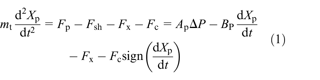
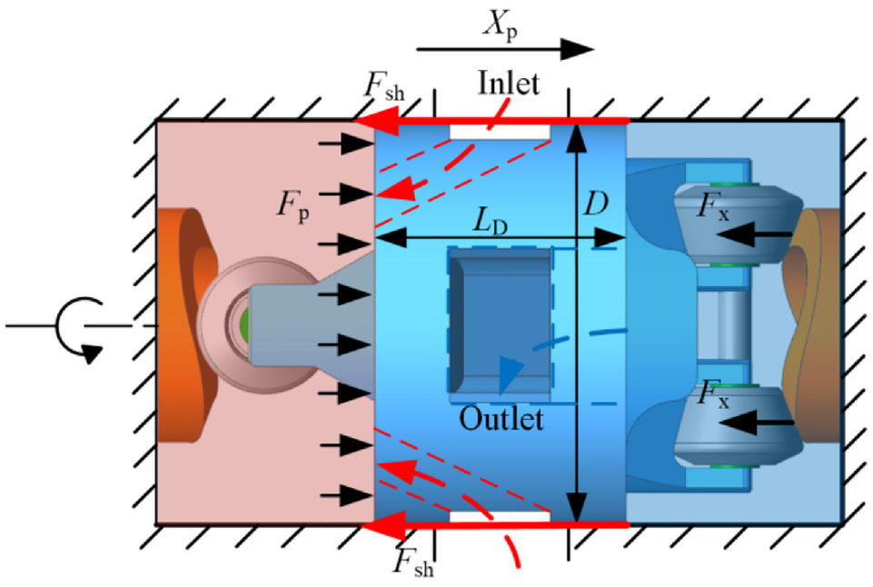
The structure schematic of single metering unit of a 2D piston flowmeter.
where

where


Schematic diagram of chambers and pipelines.
where
To calculate the resultant axial force

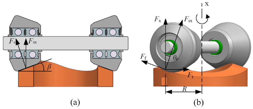
Schematic diagram of the contact forces between the cone rollers and the cam track: (a) Axial component force of the support force on the cone roller and (b) force analysis of cone rollers on the cam track.
where
The circumferential resultant force,

where
From Figure 8, when the 2D piston rotates, it is affected by the moment of inertia and the viscous shear moment,

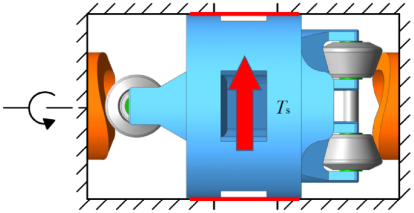
Schematic diagram of viscous damping torque.
where

Combining equations (4)–(7) to eliminate the variable,

Substituting equation (8) into equation (1), the force balance equation of the 2D piston can be described by equation (9).

Since the 2D piston flowmeter measures the flow rate by monitoring the displacement signal of 2D piston in each measuring unit, In other words, the displacement signal of 2D piston can be defined as the output signal of 2D piston flowmeter. Hence, the rotation angle,

where
Equation (10) cannot be directly substituted into equation (9) because it disobeys the condition of continuous function from the Laplace transform in next step. Therefore, it is necessary to perform a first-order Taylor expansion of equation (10) at the point
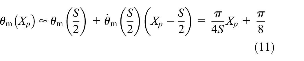
The relationship between velocity and angular velocity, acceleration and angular acceleration can be obtained by taking the first derivative and the second derivative of equation (11), respectively.
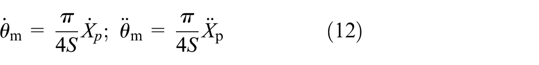
Substituting equation (12) into equation (9), a kinetic equation of 2D piston containing only two variables,

In the design of experiments, a three-position four-port servo valve is used to produce a sinusoidal flow rate under a constant pressure difference. The dynamic characteristics of the flowmeter can be obtained by comparing the displacement signals of the 2D pistons with the displacement signal of the valve spool. Therefore, the flow-continuity equation (14) and the flow rate equation of a slide valve (15) are supplemented.
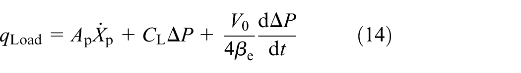

where
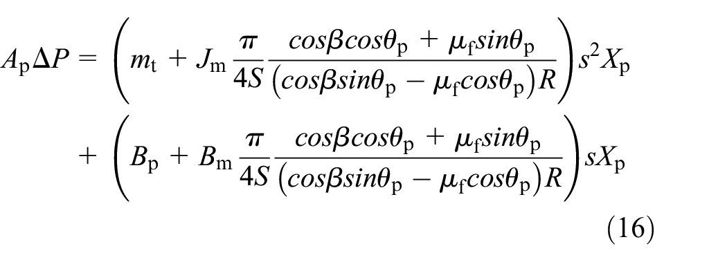
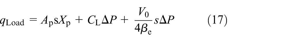

Performing the Laplace transform on equations (13)–(15) to obtain equations (16)–(18), the transfer function between the displacement of 2D piston and displacement of servo valve spool can be put forward as equation (19)
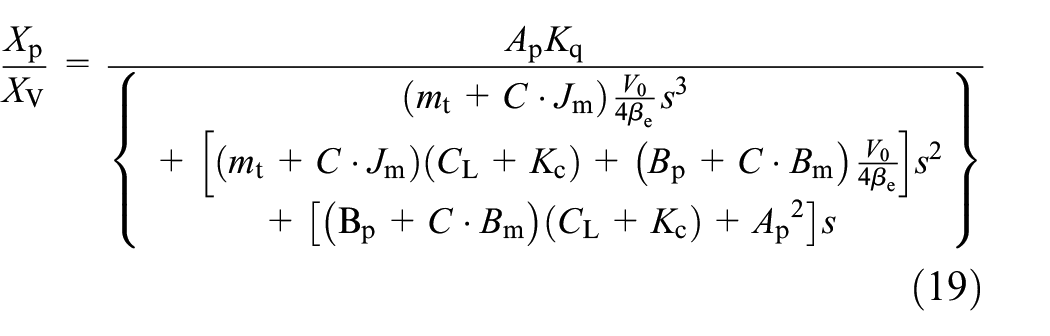
where
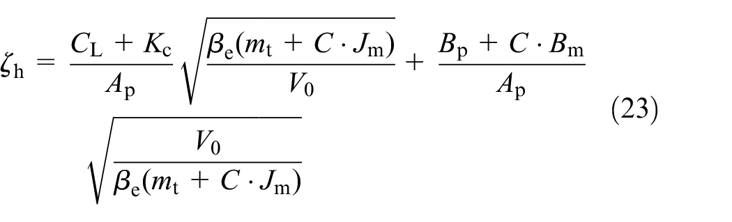
Looking into the equation (19), it consists of the integral loop and the second-order oscillation loop. So equation (19) can be rewritten into the form of equation (21)
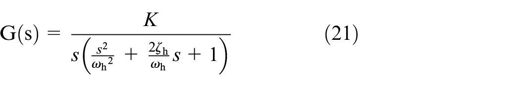
where

Simulation analysis
The derived transfer function is used to investigate the feasibility of the design and discuss the influences from some most crucial parameters. A series of simulations were performed by applying the parameters listed in Table 1.
Main parameters of 2D piston flowmeter and oil characteristics.

When the design of a 2D piston dynamic flowmeter is put on the agenda, the influence from the 2D piston diameter on the dynamic characteristic attracts the most attention. The increase of the 2D piston diameter leads to an enlargement of the mass and moment of inertia of the 2D piston. But the displacement and the pressure force applied on the cross-sectional area has also been improved exponentially.
Figure 9 shows the open-loop bode diagram of the system under different 2D piston diameters. It can find that the increase of the 2D piston diameter results in a slight and nonlinear rise of the frequency. In order to illustrate the influence of the 2D piston diameter more specifically, the hydraulic natural frequency
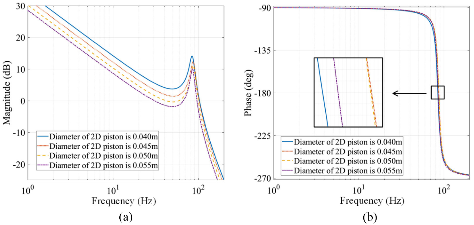
Bode diagram of the system under different 2D piston diameters: (a) amplitude frequency characteristics and (b) phase frequency characteristics.

The relationship between hydraulic natural frequency and 2D piston diameter.
As shown in Figure 10, the increase of the diameter of the 2D piston causes the hydraulic natural frequency to form a peak curve. Before the curve reaches the top, the increase of the diameter enlarges the cross-sectional area of the 2D piston, which locates at the numerator of equation (21), to enhance the piston’s sensitive. Afterward, along with the continuously raising, the mass, the moment of inertia, and the total volume of all chambers begin to climb and reduce the dynamic performance of the system. Therefore, the best diameter of 2D piston should be around 0.045 m.
The mass of 2D pistons can be changed by using different materials without changing dimensional parameters. Figure 11 illustrates the influence from the 2D piston mass. As the 2D piston mass increases, the dynamic characteristics of the flowmeter hardly change, because the 2D piston mass

The effect of different materials of 2D piston on dynamic characteristics.
Compared with the mass of the 2D piston, the total volume of the chambers from the servo valve to the flowmeter weights more on changing the system frequency. The converted mass of oil plays a major role in the total mass. Thus, when total volume of the chambers enlarges, the total mass rockets greater and directly leads to the decline of system frequency as in Figure 12. It’s reasonable to diminish the total volume of all chambers during the design process.

Influence of total volume of all chambers V0 on dynamic characteristics: (a) amplitude frequency characteristics of the systems with different V0 and (b) the hydraulic natural frequency changes with V0.
After a comprehensive consideration, the new 2D piston flowmeter is fabricated based on the parameters in Table 1, in which 0.042 m is used as the piston diameter and the 3D printed plastic piston weights 0.058 kg.
Besides, before practical application, it is necessary to evaluate the influence of an unpredictable factor, effective bulk modulus of oil, that can deform dynamic characteristic, because the hydraulic system is hardly isolated from air, and the hydraulic oil inevitably has dissolved air or even entrained air. 32 As demonstrated in Figure 13, the increase of effective bulk modulus of the oil dramatically effects the hydraulic natural frequency, which implies the importance of exhaust procedure in building up a hydraulic system.

The effect of oil effective bulk modulus
Experimental research
As shown in Figure 14, the hydraulic system for the calibrating the dynamic characteristic of 2D piston flowmeter consists of the tested flowmeter designed considering all the parameters listed in Table 1, a pump source to provide the flow rate, a relief valve to maintain the rated input pressure and control the pressure drop through the system, and a four way three position servo valve controlled by a PC to guarantee that the displacement of the spool, which is considered as the input signal in the transfer function equation (19), strictly obeys a sinusoidal curve with various frequency. The output signal of the transfer function is the displacement of one 2D piston which is obtained by a LVDT and collected through a data acquisition device. The dynamic characteristics of the prototype can be obtained by comparing the amplitude difference and phase difference between the input signal and the output signal. Parameters of the instruments and sensors mentioned above are shown in Table 2.

Test rig for calibrating the dynamic characteristic of 2D piston flowmeter: (a) test rig overview, (b) schematic diagram of test rig, and (c) the 3D printed prototype of the 2D piston flowmeter.
Details of the relevant devices.

Figure 15 shows displacement curves of the spool and the 2D piston at four various frequencies. It’s obviously to notice that the amplitude of the output displacement curve declines along with the increase of the frequency of input displacement signal. Besides, an interest phenomenon can be observed when the frequency is as low as 1 Hz in Figure 15(a). There is a small wave between two large waves, which is disappeared when the frequency goes high. This unique phenomenon is produced due to the characteristic of 2D piston flowmeter itself. In order to figure it out, three facts should be list here. Firstly, as a result from the previous research, the 2D piston flowmeter can self-distribute the flow rate to realize a continue measurement.30,31 Moreover, as seen in Figures 1 and 3, a cam track has two crests and two troughs in one complete circle. The cone rollers rotating on the cam track is like climbing over a hill. Thirdly, since the pressure at valve inlet is constant, the flow rate passing through the valve and the flowmeter is linear with the displacement of the spool. When the frequency of controlling is low, the flow rate passing through the valve in one period is relatively large than that at a high frequency. Therefore, when the frequency is as low as 1 Hz, the large amount of flow rate results in that the 2D piston climbs over the crest of the cam track, or more concretely, goes “up” and “down” in the axial direction. This phenomenon indicates that the partial displacement curve of 2D piston requires a manual reverse procedure at low frequency. And as in Figure 16, even under the same test conditions, the displacement curves of 2D piston might be dissimilar with each other at different times of test because the circumferential position of the 2D piston is random.

Displacement curves of 2D piston and spool at: (a) 1 Hz, (b) 3 Hz, (c) 5 Hz, and (d) 7 Hz.

Displacement curves of the spool and 2D piston at different tests: (a–d) Random test Data at 1Hz.
Figure 17 illustrates the amplitude frequency and phase frequency characteristics of the valve-controlled 2D flowmeter. As same as the simulation result, the phase difference between the valve spool and the 2D piston is larger than 90°. However, the −3 dB frequency is much less than expectation. This is because the design model for the 3D printing has not considered exhausting the air in the hydraulic oil during tests. When the experiment is carrying out, the air bubbles accumulates and clusters in one fluid tunnel as in Figure 18, which leads to decrease the effective bulk modulus of oil.

Bode diagram of the test rig.

Air bubbles in the 2D piston flowmeter.
The effective bulk modulus of the hydraulic oil used in the test is about 1000 MPa. But when the air bubbles are entrapped in the oil, according to Feng’s research, 33 the effective bulk modulus is reduced to 1–10 MPa.
A simulation is carried out to explore the influence of low effective bulk modulus of the oil. As shown in Figure 19, the calculated hydraulic natural frequency is around 3 Hz when the effective bulk modulus drops to 1 MPa, which fits the test results well. It can certify that the air bubbles in the flowmeter affects the dynamic performance of the prototype and verifies the correctness and accuracy of the mathematical model derived in previous section.

Comparison of the simulation results of different effective bulk modulus and the test results.
Conclusions
In this paper, a new 2D piston flowmeter is proposed for dynamically measuring the flow rate change. The architecture and the working principle are introduced together with the established mathematical models. Following, the simulation analysis based on the derived transfer function is carried out to provide factors that influence the dynamic characteristic of flowmeter. Subsequently, a prototype is fabricated with 3D printing and a test rig is manufactured as well. The experimental results show the accuracy of mathematical model and the feasibility of applying 2D piston flowmeter on dynamic measurement. The specific contributions and limitations in this paper are as follows:
The theoretical analysis points out that the 2D piston diameter would have an optimized value under a certain design background, the importance of the 2D piston mass weights much less than the total volume of all chambers.
The test results show that a 3D printed prototype can reach 4 Hz at −3 dB even under a low effective bulk modulus. The design of next generation prototype should consider more exhaust structure to diminish the amount of entrapped air in the working medium. Besides, the degassing procedure of the whole hydraulic system deserves more attentions before starting a new test.
In the mathematical model, the relationship between the dynamic performance and effective bulk modulus is only analyzed qualitatively. A detailed quantitative mathematical model considering the gas content, system pressure, and temperature has been planned in the further study.
Both the mathematical model and the prototype uses the displacement on one 2D piston due to the simplification of analysis. Considering the 2D piston flowmeter has two parallel 2D pistons, it is necessary to present a complete dynamic mathematical model including two displacements from different 2D pistons.
Using the displacement of 2D piston as the output signal has to face the effect of “climbing over a hill” when measures a low frequency sinusoidal wave of flow rate. It might be better to employ speed sensors to monitor two 2D piston’s axial velocities to directly obtain the flow rate change.
In conclusion, although it looks simple and crude, this new 2D piston flowmeter initiates a new branch under the category of measuring dynamic flow rate signals and is worthy to pay more passions.
Footnotes
Handling Editor: Chenhui Liang
Author contributions
Chuan Ding developed mathematical modeling and wrote the manuscript; Haoqi Chen wrote the original draft and performed calculation; Lichao Zhang performed data analysis; Ning Xia performed design; Under supervision by Prof. Jian Ruan.
Declaration of conflicting interests
The author(s) declared no potential conflicts of interest with respect to the research, authorship, and/or publication of this article.
Funding
The author(s) disclosed receipt of the following financial support for the research, authorship, and/or publication of this article: This research was funded in part by the Zhejiang Provincial Natural Science Foundation (Grant No. LY21E050013), in part by the National Natural Science Foundation of China (Grant No. 51805480), and in part by the National Key Research and Development Program of China (Grant No. 2019YFB2005201).