
Abstract
To address the effect of clearance on the efficiency of two-dimensional piston pumps, this paper proposes a novel two-point contact type stacked roller support two-dimensional piston pump that eliminates the effect of guide rail and cone roller clearance on mechanical efficiency and volumetric efficiency in the inertia force-balance two-dimensions piston pump. It achieves two-way force balance support for the hydraulic static pressure and inertia force of the cone rollers through the overlapping mutual support and friction transmission of the double-layered cone rollers, which can effectively compensate for the gap between the rollers and the guide rail. The structure and operating principle of a two-dimensional piston pump are described first in this study, establish the mechanical efficiency model and volumetric efficiency model. Building an experimental bench for testing, the outcome is consistent with the theoretical analysis, and the difference is within 6%, demonstrating that the theoretical analysis is correct.
Keywords
Introduction
Compared with other transmission methods such as mechanical transmission and electric transmission, hydraulic transmission has a series of advantages such as high power density, compact structure, easy automation, and good dynamic performance. It is widely used in construction machinery, robots fields.1–3 The hydraulic pump, located at the heart of the hydraulic system, is in charge of transforming mechanical energy into hydraulic energy by supplying the hydraulic system with exact pressure and flow of a transmission medium.4,5 The axial piston pump is the most common of these, with three critical friction pairs: cylinder-port plate, piston-cylinder block, and slipper-swash plate. These three friction pairings limit the axial piston pump’s speed and power density growth.6–8 Additionally, the axial piston pump’s cylinder body will experience the piston’s overturning moment while it is operating, which could result in failure and fracture in extreme circumstances.9–18 Scholars at home and abroad have worked tirelessly to analyze the sliding friction pair in the axial piston pumps, striving to free it from its restrictions on speed and power density.14,18–26
Xing et al.’s team has been engaged in the research of two-dimensional hydraulic components for a long time, applied the two-dimensional concept to hydraulic pumps, and proposed a two-dimensional piston pump. 27 Because the two-dimensional piston pump has an axisymmetric structure, the piston is constantly in a condition of balance between radial and axial forces. The two-dimensional piston pump’s guide-roller mechanism uses rolling friction as its primary kind of friction to reduce the effects of conventional friction and circumvent the performance limitations imposed by conventional friction pairs.28–30 The two-dimensional piston pump is a positive displacement pump essentially, so there are some challenges such as cavitation and overturning moment. The working chamber of the two-dimensional piston pump’s pressure impact product and the instantaneous displacement change are what create flow pulsation. Therefore, Jin et al.31–33 presented a two-dimensional piston dual pump that uses the insertion and misalignment of the two pistons to lessen the hydraulic pump’s flow pulsation. In order to minimize the negative effects brought on by the axial force overturning moment, Huang et al.34,35 showed a two-dimensional piston pump that was force-balanced. This pump balances the cylinder body and reduces vibration and noise by using an inventive construction of inner and outer pistons. Huang et al., 36 analyze of the force-balanced two-dimensional transmission mechanism’s churning loss using CFD and experimental research to the development of an empirical equation for churning loss torque. However, during the experiment, it was found that there is a gap which product by machining errors and assembly errors between the two guides rail sets and the cone roller. At high speeds, the existence of this gap will make the guide rail continue to hit the stacked rollers, aggravate vibration.
In order to reduce the gap’s impact on the two-dimensional pump’s efficacy, the author suggests a brand-new two-point contact type stacked roller support two-dimensional piston pump (two-point stacked roller two-dimensional piston pump). The double-layer cone rollers’ overlapping mutual support and friction transmission allow for two-way force balancing of the double-piston hydraulic static pressure and inertia force. When the number of rollers is increased, the distance between the guide rail and the cone roller is effectively reduced while the number of strokes and displacement are increased. The cross-sectional area and working stroke of the piston are significantly reduced due to the 18 times that oil is sucked in and discharged in one spin, and the improvement in power density. The piston’s cross-sectional area is reduced, which lessens the pressure exerted on it by the high-pressure chamber, lowers the input torque needed to operate, and improves mechanical efficiency. The structure and operation of the two-point stacked-roller two-dimensional piston pump are thoroughly described in this paper. Following that, a mechanical and volumetric efficiency analytical model was developed. First the force analysis of a single piston, and a mechanical efficiency model is built after modeling the guide rail’s space surface. The regularity of the flow and pressure changes in a single oil chamber is then used to create a volumetric efficiency model. Based on this, an experimental prototype was created, processed, and an expert experimental bench was constructed. Test the experimental prototype’s mechanical and volumetric efficiency at varied load pressures and speed. The sources of the inconsistencies in the results are then determined by comparing the theoretical analysis and experimental outcomes.
Structure
Figure 1 depicts the two-point stacked-roll two-dimensional piston pump’s structural layout. The two-point stacked-roll two-dimensional piston pump consists of a drive rail group, a balance rail group, a stacked roller set, and a distribution cylinder group. The stacked roller set of the 2D piston pump consists of six cone rollers stacked in pairs. During operation, the stacked cone roller sets adhere closely to the surfaces of the two guide sets by load pressure to ensure that the 2D piston and piston ring work with the required stroke. The drive rail group, as depicted in Figure 1(b), is made up of pistons and drive guide rails. A pair of conjugated end-face cams with equal acceleration and deceleration surfaces make up the left drive guide rail and the right drive guide rail. The right drive rail is mounted on the piston in a peak-to-valley fashion. As shown in Figure 1(c), the balance rail group is composed of pistons and balance guide rails. The driving guide rail group and the balancing rail group always have opposite axial movement directions, but their structure is the same. The installation phase is different by half of the operating cycle. The distribution cylinder assembly is made up of the main shaft, the distribution cylinder block, the left flange baffle plate, the right flange baffle plate, and the bushings, as seen in Figure 1(d). The distribution cylinder has six distribution windows evenly distributed in the last week, and there are three left distribution grooves and three right distribution grooves on the pump casing. To achieve oil suction and discharge, they are positioned in a staggered axial orientation and communicate alternately with the distribution window on the distribution cylinder.
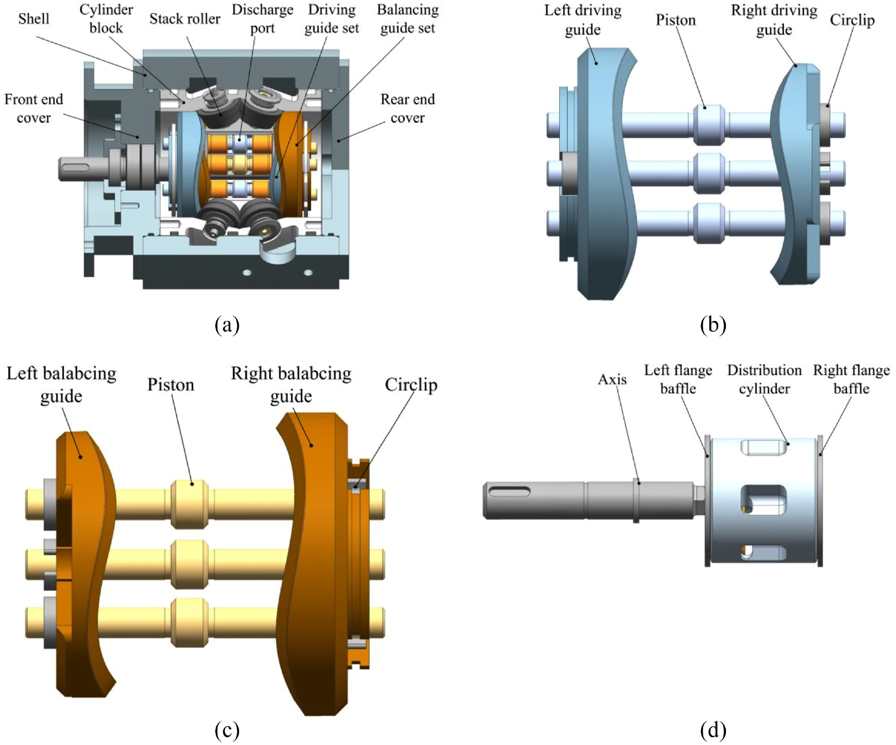
The structure schematic diagram of the two-point stacked-roller two-dimensional piston pump: (a) structure diagram, (b) drive rail set, (c) balance rail set, and (d) distribution cylinder assembly.
Figure 2 depicts the two-point stacked-roller two-dimensional piston pump’s flow distribution method: A, B, and C are used to represent the left distribution grooves in the figure, while D, E, and F are used to represent the right distribution grooves. M stands for the piston, and G, H, I, J, K, and N are used to represent the distribution windows. Low-pressure oil is shown in the blue area and high-pressure oil is shown in the red area. The main shaft’s rotational angle is 0°, the distribution grooves A, B, C, D, E, and F do not connect with the distribution windows G, H, I, J, K, and N, the piston M is at the right-most end, the left chamber has the highest volume, and the right chamber has the smallest volume, as shown in Figure 2(a). The distribution grooves A, B, C, D, E, F and the distribution window G, H, I, J, K, N start to communicate when the main shaft rotates from 0° to 30°, which also causes the piston M to accelerate and travel to the left. When the main shaft rotates at a 30° angle, as shown in Figure 2(b), the communications area between the distribution grooves A, B, C, D, E, and F and the distribution windows G, H, I, J, K, and N is at its greatest. The piston M slows down and moves to the left as the main shaft rotates from 30° to 60°. Additionally, when the right chamber R expands and the left chamber L contracts, the communication space between the distribution grooves A, B, C, D, E, F and the distribution windows G, H, I, J, K, N is confined. The distribution windows G, H, I, J, K, and N are in a state of non-communication when the main shaft rotates at 60°, as shown in Figure 2(c), with the left chamber L having the smallest volume and the right chamber R having the largest volume. As the main shaft rotates from 60° to 90°, the volume of the left chamber L increases, the volume of the right chamber R decreases, the piston M accelerates and travels to the right, and the distribution grooves A, B, C, D, E, F and the distribution window G, H, I, J, K, N begin to communicate. When the main shaft rotates at 90°, as shown in Figure 2(d), the volumes of the left L and right chambers R are equal, and the communication area between distribution grooves A, B, C, D, E, F and distribution windows G, H, I, J, K, N is maximized. The piston M slows down and slides to the right while the main shaft rotates from 90° to 120°. At the same time, the right chamber R continues to get smaller and the left chamber L continues to get bigger. Until the spindle spins at 120° and returns to the condition as shown in Figure 2(a), the communication area between the distribution grooves A, B, C, D, E, and F and the distribution windows G, H, I, J, K, and N decreases. During this operation, the right distribution grooves D, E, and F continue to feed low-pressure oil while the left distribution grooves A, B, and C always discharge high pressure oil. The left and right chambers alternately operate as oil suction and discharge units. For each motor spin, the left and right chambers complete three cycles of oil suction and discharge.

The flow distribution diagram of two-point stacked-roll two-dimensional piston pump: (a) the rotating 0° state, (b) the rotating 30° state, (c) the rotating 60° state, and (d) the rotating 90° state.
Analytical modeling
Mechanical efficiency
The rail Surface Equation
The two-point stacked-roll two-dimensional piston pump relies on the stacked roller set to force the guide rail and the piston to reciprocate to ensure that the two-dimensional piston pump can work normally. As a result, the space surface model of the stacked roller set and the guide rail must be created in order to develop the mechanical efficiency model of the two-point stacked-roll two-dimensional piston pump.
Figure 3 depicts the cone roller’s angled relationship. Among them,

The schematic diagram of the cone roller.
The space surface equation of the guide rail can be established using information from the cone roller’s shape, motion law, and guide rail. Through homogeneous coordinate transformation, the process of transforming the motion coordinate system

The homogeneous coordinate transformation diagram.
Rotate the motion coordinate system

Among them,
Only one of the surfaces needs to be studied because the guide rail’s surface is made up of three equal acceleration and deceleration surfaces. The expression of the guide rail’s axial displacement is shown in equation (2).

Where
According to the single-parameter surface family envelope theory, equation (1) can be written as a function with three variables.

Substituting equation (3) into

Spatial angle function
To solve the tangent vector, normal vector at the contact point, and their projection on the bottom surface of the roller body, the parameterization of the guide rail surface equation is used. This makes it possible to calculate the relationship between each vector’s space angles, the rotation angle
The friction force

Consider the direction of the positive pressure component as being the projection
Referring to Figure 4, the unit vectors
Where


Mathematical model
The guideway of the two-point stacked-roller two-dimensional piston pump is made up of six parts of equal acceleration and equal deceleration surfaces, thus one of these sections is chosen for investigation.
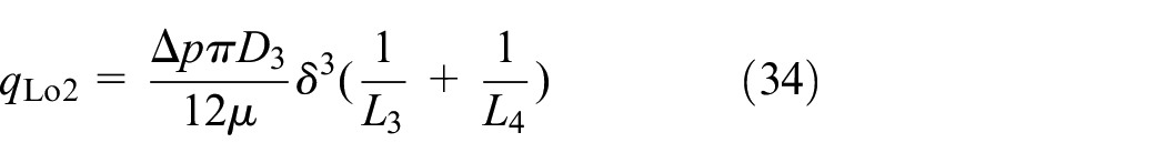
The inner and outer guide rail groups of the cam guide rail group are constantly in touch with the stacked roller set due to the gap compensating capabilities of the pump, which puts them under stress. The drive rail group and the balance rail group are in comparable situations, so the study will use the balance rail group as an example.
Taking the right limit position of the balance guide rail group as the starting point, when the pump spins from 0° to 30°, the rails accelerate and travel straight to the left; when the pump rotates from 30° to 60°, the rails decelerate and go straight to the left. The expression for the acceleration

Where
Figure 5 depicts the force analysis of the balanced guide set. Newton’s second theorem can be used to list the balancing equation in the axial direction of the balance guide rail group, as illustrated in equation (12).

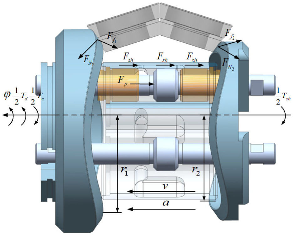
The force of balance guide rail group from 0° to 60°.
Where
Because the large guide rail is in the return section, the applied force is at the same angle as mentioned in the previous section. The small guide rail, on the other hand, is in the push section and its angular phase differs from the angle mentioned in the previous section by half a working cycle. When the number of cone rollers is taken into account, the force of the cone rollers on the rail must be multiplied by half.
Where
The high-pressure force


In equation (13),
In equation (14),
Where
According to the torque balance, the circumferential balance equation of the balance guide rail group can be listed, as shown in equation (17)
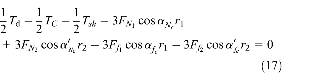
In the equation,
The following equation shows the oil shear torque


In equation (18),
The churning loss
The stacked roller set force analysis is used to calculate the force exerted by the stacked roller set on the guide rail. Because the bearing pressure and operating conditions of the six cone rollers are the same, only one of them is studied, as shown in Figure 6.

The schematic diagram of the force of the cone roller.
Where
Newton’s second theorem states that the equilibrium equations in the


Where
To make the mathematical model simpler, convert all frictional forces to the friction coefficient normal pressure product. And consider that
According to the above premise, the expression of

The mechanical efficiency of the two-point stacked-roll two-dimensional piston pump can be calculated by equation (24).

Where
Volumetric efficiency
The driving guide rail group and the balance guide rail group of the two-point stacked roller two-dimensional piston pump function on the same principles, and the volumetric efficiency is modeled using the balancing guide rail group as an example. The left chamber has the most capacity in its initial position.
When the compressibility of the oil is considered, equation (25) describes the instantaneous pressure shift in the left chamber.
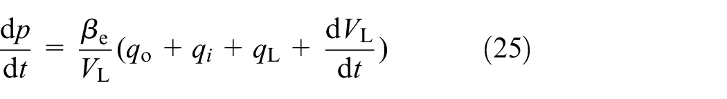
where
The interaction of the piston and bushing, which are both fixed to the guide rail, determines the instantaneous volume of the left chamber. The piston’s movement speed
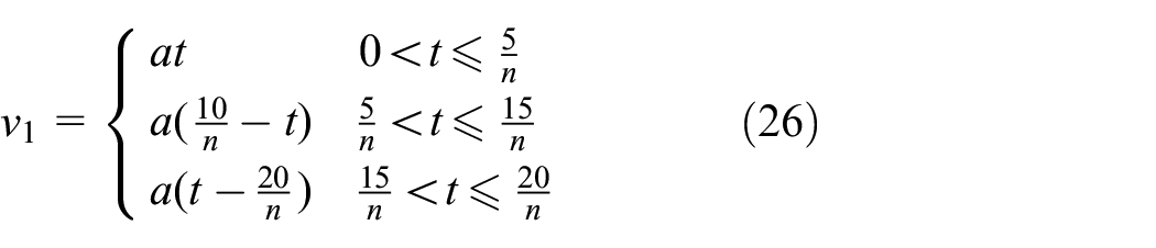
Where
The speed

Where

The
According to standard orifice can be used to express inlet flow and output flow, as show in equations (29) and (30).
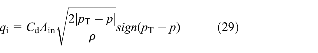

Where


Where
The two-point stacked-roller two-dimensional piston pump’s leakage

The schematic of the leak flow.
The leakage
The external leakage

Where
Internal leakage

Internal leakage
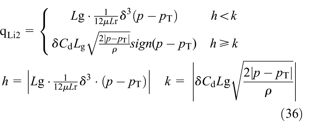


The variation pattern of the distance
To sum up, the leakage

Finally, throughout the process from 0° to 120°, by integrating the output flow

The time
Theoretical analysis
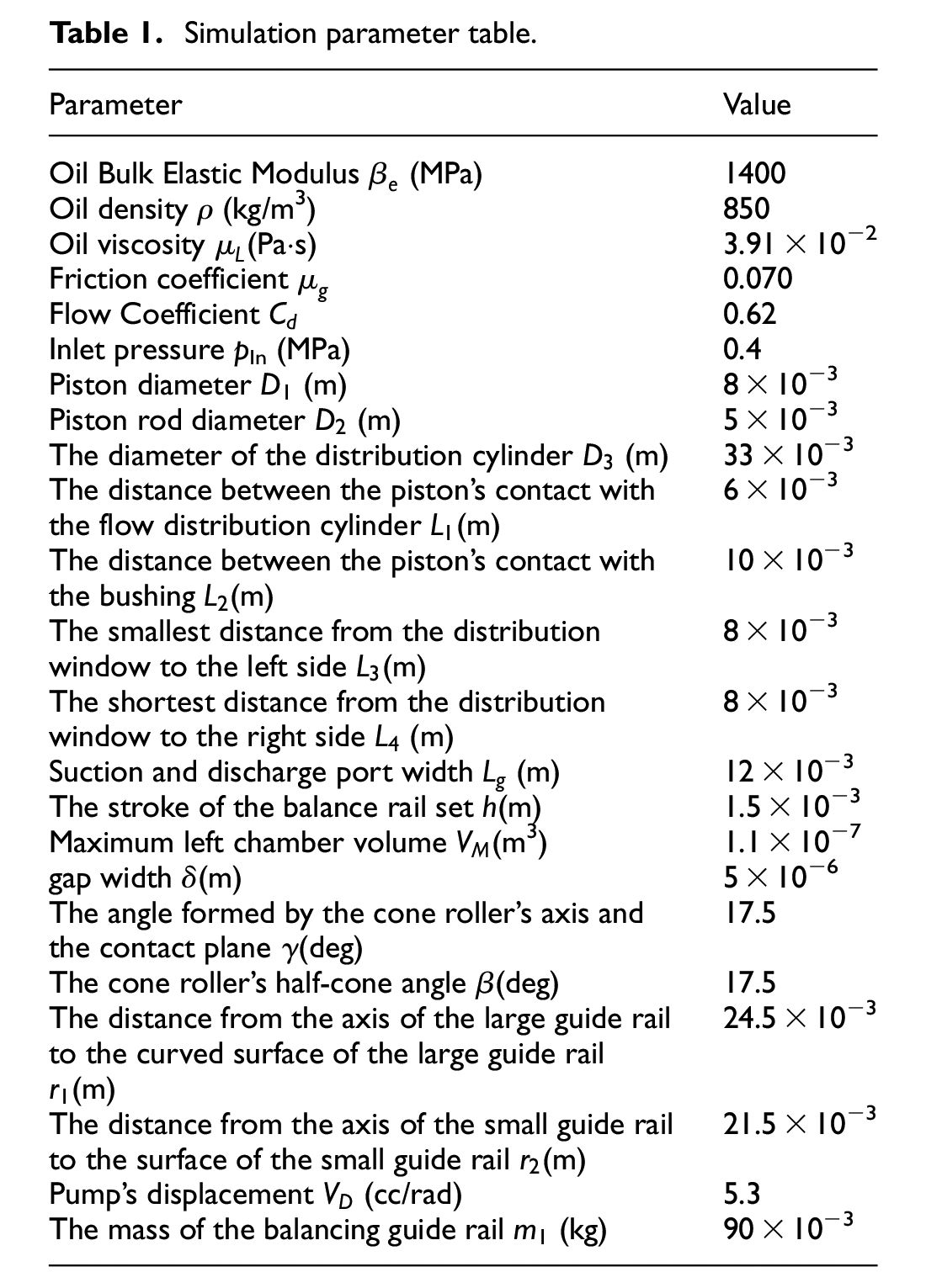
The mathematical model described above is used to investigate the effect of rotational speed and load pressure on mechanical and volumetric efficiency, No. 15 hydraulic oil is selected as the working medium. Table 1 displays the key parameters.
Simulation parameter table.
Influence of rotational speed and load pressure on mechanical efficiency
Take the balanced guide rail group as an example, Figure 9 is the torque change curve. The graphic shows that the torque grows with increasing load pressure and speed, and that it changes quickly when the guide rail reaches the neutral point. This is due to the change in acceleration direction and the sudden change in the support force applied by the cone roller to the group of balance guide rails.

Torque
As illustrated in Figure 9(a), as the load pressure increases, so does the torque due to a variety of factors, including an increase in the support force
As the rotating speed increases, both the oil shear torque

Pressure
The link between mechanical efficiency, speed, and pressure is depicted in Figure 11. The two-point stacked-roll two-dimensional piston pump eventually requires more torque as rotational speed rises, and mechanical efficiency declines; The mechanical efficiency rises as the load pressure steadily rises because the pressure rise speed is greater than the torque rise speed.

The connection between rotational speed, load pressure, and mechanical efficiency: (a) different load pressure at speed at 4000 r/min and (b) different speed at load pressure at 8 MPa.
Influence of rotational speed and load pressure on volumetric efficiency
Figures 12 and 13 show the output flow curves of the left chamber for various load pressures and speed conditions. The graphic shows that the output flow rises as the rotational speed rises and is less influenced by the load pressure. Because the left chamber’s immediate pressure is lower than the load pressure when oil discharge begins and the left chamber stops sucking in oil, oil will backflow.

Output flow

Output flow
While the rotating speed remains constant, the peak and duration of the backflow flow increase as the load pressure increases, as shown in Figure 12(b). As the load pressure rises, so does the pressure difference between the left chamber’s instantaneous pressure and the load pressure. This allows the backfill flow to assist the left chamber’s instantaneous pressure to rise to system pressure and start oil discharge.
As shown in Figure 13, increasing the rotating speed increases the output flow and peak value of the oil backflow, but decreases the duration. This is because, when a particular load pressure is assumed, the rotation speed increases, the rotation length decreases, and the peak value of oil backflow rises while the demand for oil backflow remains constant.
The leakage flow fluctuation curve for varied load pressures and rotational speeds is shown in Figure 14. When can be seen in Figure 14(a), as the pressure rises, the leakage flow rate increases, and as the rotating speed rises, the minimum value lowers. This is because leakage flow is estimated by subtracting shear flow from differential pressure flow; the greater the load pressure, the greater the differential pressure flow. When the rotational speed is fixed, the piston moves at the same rate as before, conserving shear flow and increasing the leakage flow rate. The differential pressure flow does not vary as the rotational speed increases while the load pressure remains constant; nevertheless, as the piston moves faster, the minimum value of the leakage flow drops. When the oil is released from the left chamber, the piston’s movement speed rises and then falls as the rotation angle increases, causing the leakage flow to climb and then reduce.

The schematic diagram of leakage flow
The relationship between volumetric efficiency, load pressure, and rotating speed is depicted in Figure 15. The volumetric efficiency curve, as depicted in the diagram, is consistent with the previous investigation’s findings. Backflow and oil loss increase as load pressure increases when the rotation speed remains constant, while volumetric efficiency decreases. While the load pressure remains constant and the rotating speed increases, oil backflow and leakage are reduced, and volumetric efficiency improves.

The connection between rotational speed, load pressure, and volumetric efficiency: (a) different load pressure at speed at 4000 r/min and (b) different speed at load pressure at 8 MPa.
Experiment analysis
The two-point stacked-roll two-dimensional piston pump is displayed in Figure 16 and its important parameters are presented in Table 2 to confirm the aforementioned mathematical model and simulation findings.

Two-point stacked-roll two-dimensional piston pump prototype.
The main parameters of the experimental prototype.

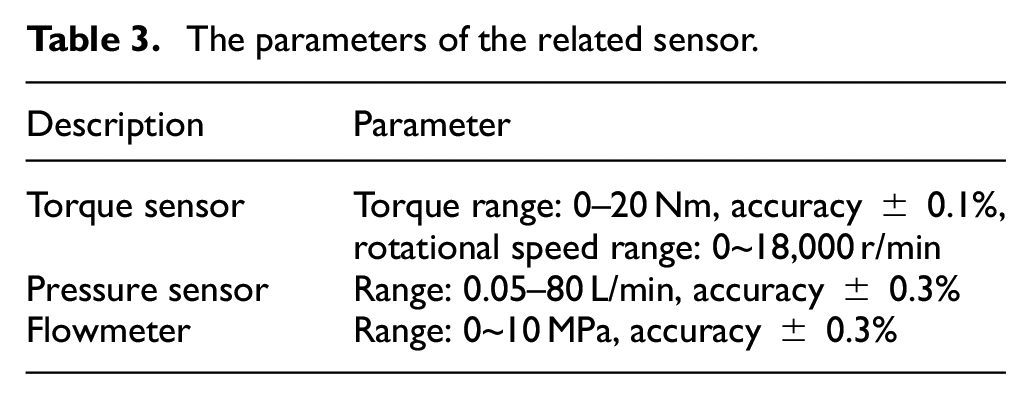
An experimental bench, as shown in Figure 17, was built to test the volumetric and mechanical performance of the experimental prototype at various rotational speeds and load pressures. A gasoline supply pump, motor, torque-speed sensor, flow meter, overflow valve, and pressure sensor comprise the test bench. The test bench uses the data acquisition card to send data from the flowmeter and torque-speed sensor to the computer. The critical sensor parameters are listed in Table 3.

The experimental bench’s conceptual design: (a) experiment bench system diagram and (b) physical map of the experimental bench.
The parameters of the related sensor.
The temperature of the experimental environment is controlled at 25°. The pump will be cooled to room temperature before the experiment, and during the test, the speed and pressure of the pump under test are rapidly ramped up to the target speed and pressure to minimize the effect of temperature rise.
Experimental analysis of load pressure and rotational speed on mechanical efficiency
Set the motor speed to 4000 rpm before adjusting the relief valve to control the pump station’s output pressure. When the torque stable, record the information to determine the link between mechanical efficiency and load pressure, and compare it to the simulation’s outcomes, as illustrated in Figure 18(a). When the torque display was stable, the pump station’s output pressure was adjusted to stabilize it at 8 MPa, and the speed was increased in units of 1000 r/min. The simulation results were then compared to the data to determine the link between mechanical efficiency and rotational speed, as illustrated in Figure 18(b).
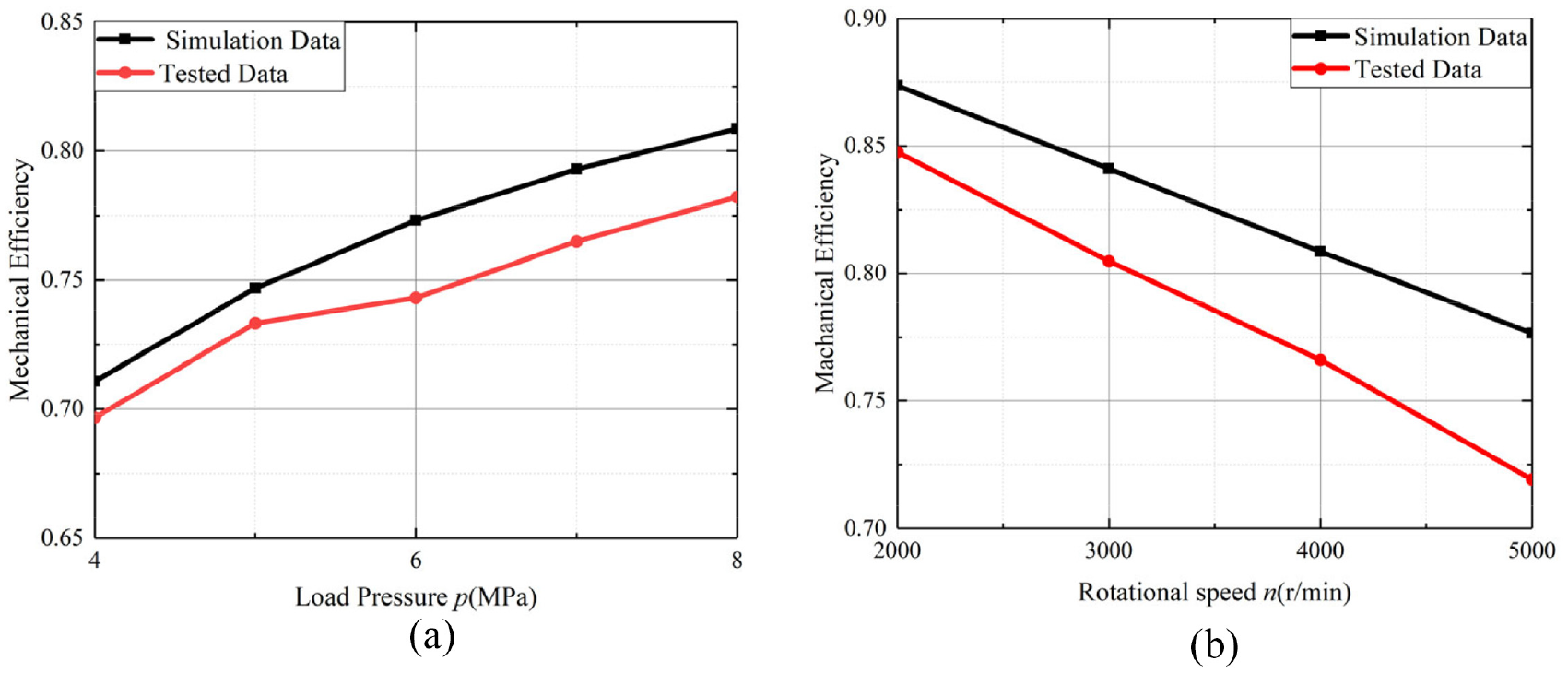
Mechanical efficiency experimental simulation comparison chart: (a) different load pressure at speed at 4000 r/min and (b) different speed at load pressure at 8 MPa.
Although the modeling findings and experimental data appear to be in good agreement, the gap grows as load pressure and speed do as well. One reason for this is that as the experiment goes on, the oil temperature rises and the viscosity drops, reducing the lubricating effect and affecting mechanical efficiency. On the other hand, the cone roll’s condition changes as a result of the change in rotational speed and load pressure.
Experimental analysis of volumetric efficiency of load pressure and rotational speed
Repeat the aforementioned experimental processes and examine the flowmeter findings to determine the volumetric efficiency at various load pressures and rotating speeds.
The experimental findings, which are depicted in Figure 19, are in line with the shifting trend of the modeling curve. The experimental and simulated results differ just slightly.

Volumetric efficiency experimental simulation comparison chart: (a) different load pressure at speed at 4000 r/min and (b) different speed at load pressure at 8 MPa.
On the one hand, this is because after a time of operation, the temperature of the oil rises and the viscosity lowers, increasing leakage. When the cone roller is running, the cone roller will move in the direction of the central axis due to the constant change in pressing force, causing the eccentricity of the piston and the flow distribution.
In conclusion
In this paper, a novel two-point contact type stacked roller support two-dimensional piston pump is proposed. The mathematical modeling of the pump’s mechanical and volumetric efficiency was followed by an analysis of the impact of load pressure and speed on efficiency and the construction of an experimental bench for testing the two-dimensional piston pump. Following the validation of the mathematical model, the following results were drawn:
It is clear from the experimental and modeling results that mechanical efficiency will improve along with load pressure. The two effects of increasing the load pressure are as follows: To begin with, it increases the force between the cone roller and the guide rail, lowering mechanical efficiency. Second, increasing the load pressure allows more force from the high-pressure chamber to be exerted on the piston, boosting mechanical efficiency. However, because the former’s magnitude is worse than the latter’s, mechanical efficiency increases as load pressure increases. Furthermore, increasing the rotation speed improves mechanical efficiency by reducing losses caused by oil churning and shear flow. Although there is only a minor difference between the modeling and experimental results, the inaccuracy grows with speed and load pressure. This is because the oil’s temperature rises and viscosity decreases as the experiment goes, reducing lubrication and mechanical efficiency. The type of rolling friction between the guide rail and the cone roller is altered by increases in rotational speed and load pressure, on the other hand, which lowers mechanical efficiency.
The experimental and modeling results reveal that when load pressure increases, volumetric efficiency decreases due to increased oil loss and backflow. Increasing rotational speed also increases shear flow, which decreases leakage and improves volumetric efficiency. Despite the minor gap between the modeling and experimental results, the inaccuracy grows with speed and load pressure. This occurs as the temperature of the oil rises and the viscosity lowers with time, resulting in increased leakage. In contrast, as the pressing force changes, the cone roller shifts in the direction of the central axis, causing the piston and the flow distribution cylinder to be eccentric and increasing leakage.
Footnotes
Handling Editor: Chenhui Liang
Author contributions
Data curation, C.R.; writing – original draft preparation, C.R.; writing – review and editing, C.Z.; funding acquisition, J.R. and S.L.; formal analysis, H.W.
Declaration of conflicting interests
The author(s) declared no potential conflicts of interest with respect to the research, authorship, and/or publication of this article.
Funding
The author(s) disclosed receipt of the following financial support for the research, authorship, and/or publication of this article: This research was funded by the National Key Research and Development Program of China, grant number 2019YFB2005202.