
Abstract
The two-dimensional piston pump stands as an optimal power component within pump-controlled hydraulic systems due to its utilization of a rolling friction pair. However, the sustained efficiency of the two-dimensional piston pump over prolonged operational periods remains unverified, primarily owing to the insufficient exploration of the wear mechanism inherent to its unique conjugate rolling friction pair. This study combines theoretical investigation and experimental verification to determine that the primary wear trajectory of the conjugate rolling friction pair is concentrated in the region where the roller moves from the low point to the high point of the cam. The wear is most severe at the mid-point of the cam, with a depth of up to 14 μm, which is consistent with the theoretical analysis. Furthermore, experimental observations unveil inconsistencies in the two-point support of the conjugate rolling friction pair, alongside an observed impact of preload force on the wear phenomenon. These findings furnish crucial theoretical underpinnings for the prospective optimization of design strategies in future endeavors.
Keywords
Introduction
Traditional construction machinery predominantly relies on valve-controlled hydraulic systems as its primary hydraulic transmission system. However, the implementation of energy policies by various countries1–3 has underscored the persistent challenges of low efficiency and inadequate energy conservation inherent in valve-controlled hydraulic systems.4,5 Consequently, pump-controlled hydraulic systems, exemplified by electro-hydraulic actuators (EHAs), have emerged as viable alternatives to replace valve-controlled systems, particularly in small-scale construction machinery.6–8
EHAs represent a common type of pump-controlled hydraulic systems, typically comprising a motor, a hydraulic pump, and a hydraulic actuator. In EHAs, axial piston pumps are commonly employed owing to their superior efficiency, particularly under high loads.9–11 However, the use of axial piston pumps in EHAs is limited due to their sliding friction pairs.12–15 For instance, during startup under load, EHAs systems require an unloading valve for operation. Moreover, tasks involving high frequency switching between forward and reverse rotation, rapid speed changes, cannot be efficiently executed.16,17 For this purpose, enhancements were made to the axial piston pump. Ensuring surface sealing as a foundational requirement, we transitioned the transmission mechanism from one comprised of slippers and a swash plate to one consisting of rollers and cams.18–20 The sliding friction pair, constituted by the two-dimensional (2D) piston and the cylinder, remains unaffected by overturning moments and loads. On the other hand, the conjugate rolling friction pair, comprised of rollers and cams on both sides, operates independently of an oil film, thus rendering the 2D piston pump highly suitable as the power component for EHAs.
The EHA developed based on the 2D piston pump is currently undergoing long-term life verification. However, during testing, wear was observed on the cam of the conjugate rolling friction pair. This type of wear can lead to abnormal noise during roller rotation and, in severe cases, may cause the 2D piston to become stuck. While axial piston pumps have been extensively studied regarding their sliding friction pairs, Lyu et al. established a wear model between the piston and cylinder using the finite element method, focusing on the impact of surface roughness and oil film on wear.21,22 Jiao et al. investigated the running-in process of the distribution pair in axial piston pumps and found that higher rotational speed and initial roughness can shorten the running-in time, while higher pressure tends to increase the friction coefficient. 23 Additionally, material selection plays a crucial role in studying friction pair wear. Huang et al. conducted experiments and discovered that utilizing quenched-treated and nitrated 38CrMoAl and CuPb15Sn5 materials as valve plate and cylinder body materials can enhance the frictional performance of the distribution pair in axial piston pumps. 24 However, research on the wear of the conjugate rolling friction pair in 2D piston pumps remains nascent. For instance, Wang et al. investigated the mechanical efficiency of a stacked rolling 2D piston pump’s transmission device and derived the pump’s mechanical model through force analysis. 25 Similarly, Huang et al. explored incorporating roller deformation into the mechanical model using Hertz contact to analyze the mechanical efficiency of such pumps. 26 Furthermore, experimental studies have demonstrated that 2D piston pumps can efficiently operate without relying on an oil film during loaded start-up. 27 Despite efforts by Lu et al., Chen et al., and others to address this wear issue by modifying the mechanical structure, experiments have revealed that wear in conjugate rolling friction pairs is a common occurrence.28,29
To investigate the wear issue in conjugate rolling friction pairs, this study employs theoretical modeling to pinpoint the cam wear location. Unlike traditional wear models solely focused on force analysis, this article innovatively integrates considerations of pressure variations within the pump induced by the oil delivery process, rendering the model more accurate and practical. During the experimental stage, we employed electron scanning microscopy and a white light interferometer for the first time to quantitatively detect the wear of flat rollers and cam components after long-term operation. This approach allowed us to obtain detailed two-dimensional and three-dimensional morphological characteristics of the surface profile, revealing the wear patterns. These observations enable the precise identification of wear locations and underlying causes, providing robust support for subsequent maintenance and optimization.
Conjugate rolling friction pair mechanical model
To comprehensively assess the areas prone to wear on the cam surface, it is imperative to initiate a force analysis of the conjugate rolling friction pair.
Force analysis
Figure 1 illustrates a schematic structural diagram of a 2D piston pump. The 2D piston is connected to the roller via a suspension system. When driven by the rotating machinery, the 2D piston rotates at a constant speed, resulting in reciprocating motion constrained by the conjugate rolling friction pair. Notably, the 2D piston incorporates distribution grooves that effectively link the left and right working chambers to the oil suction and discharge ports, optimizing the intake and discharge of oil. 30 Additionally, Figure 1 depicts the initial state, assuming the 2D piston is at 0° rotation.

2D piston pump schematic structural diagram.
The force analysis of the rotating component is shown in Figure 2. When the 2D piston rotates from 0° to 45° (clockwise from left to right), the left cam exerts a horizontal left support force Fx on the roller. This force must overcome the viscous resistance Fsh resulting from the gap between the 2D piston and the cylinder, as well as the hydraulic force Fpp generated by the oil discharge from the left chamber. Furthermore, owing to the consistent acceleration and deceleration design of the cam surface shape, the 2D piston will also undergo leftward motion with uniform acceleration a. Following Newton’s second law, the force equilibrium equation can be expressed by equation (1).
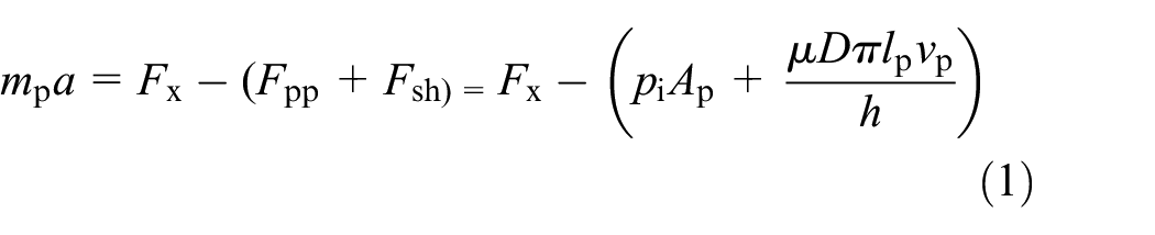
where mp describes the mass of the driving set; pi describes the pressure difference between the left and right chambers; Ap describes the cross-sectional area of the 2D piston; μ describes the oil dynamic viscosity; D describes the 2D piston diameter; lp describes the length of the 2D piston; h describes the gap between 2D piston and cylinder block.

The force analysis of the rotating component.
In equation (1), the velocity vp and acceleration a of the 2D piston movement are determined by the rotational speed n and the cam stroke Ls, as illustrated in equations (2) and (3).


where ω describes the rotational angular velocity of the 2D piston, t is the rotational time of the 2D piston form the initial state.
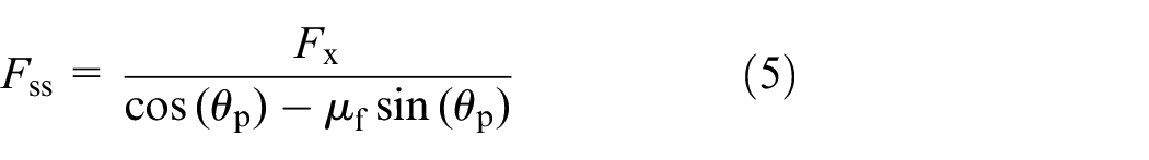
As illustrated in Figure 3, when the left roller moves along the cam guide rail from its lowest to highest point, it encounters a perpendicular support force denoted as Fss from the cam surface. Except at the lowest and highest points, there exists an angle θp between this support force Fss and the horizontal left support force Fx acting on the roller. Additionally, due to rolling friction, the roller experiences a tangential frictional force denoted as Ff, which is proportional to the support force Fss. These parameters, specifically the support force Fss and the rolling friction force Ff, are crucial indicators for assessing the severity of wear on the cam surface. The rolling friction force Ff can be calculated using equation (4).

where μf is the rolling friction coefficient, and studies have proven that its value is 0.001. 27

Force analysis of the left roller on as the roller rolls from the lowest point to the highest point of the cam.
Since the horizontal left support force Fx represents the resultant force along the x-axis of both the support force Fss and the rolling friction force Ff, the support force Fss can be computed using equation (5). 26
When the roller rolls on the cam surface, its motion direction relative to the horizontal plane forms an angle θp, which varies with the roller’s velocity. At a point of contact between the roller and the cam, the line connecting the roller’s center to this point forms an angle θp with the x-axis. Thus, the mathematical representation of θp is provided by equation (6). 31

where Rr is the radius of driving set.
When the 2D piston rotates from 45° to 90°, it undergoes a leftward motion with uniform deceleration a. The force analysis of the rotating component in this range is consistent with that from 0° to 45°, except that the acceleration is negative, indicating a direction toward the right.
Chamber pressure analysis
The pressure difference pi between the left and right chambers, as mentioned in equation (1), is conventionally presumed to be equivalent to the load pressure. Nonetheless, to provide a more precise depiction of the effects stemming from the alternating oil suction and discharge within the working chamber on the pressure differential between the left and right chambers, it becomes imperative to model and investigate the chamber pressure.
Modeling the chamber pressure analysis starts from the pump’s initial state, where the left chamber is at maximum volume, while the right chamber is at minimum volume. The expression governing the velocity vp of the 2D piston is delineated in equation (2). According to equation (2), the velocity vp of the 2D piston is determined, enabling the depiction of the temporal variations in the volume of the left and right chambers, as depicted in equations (7) and (8).

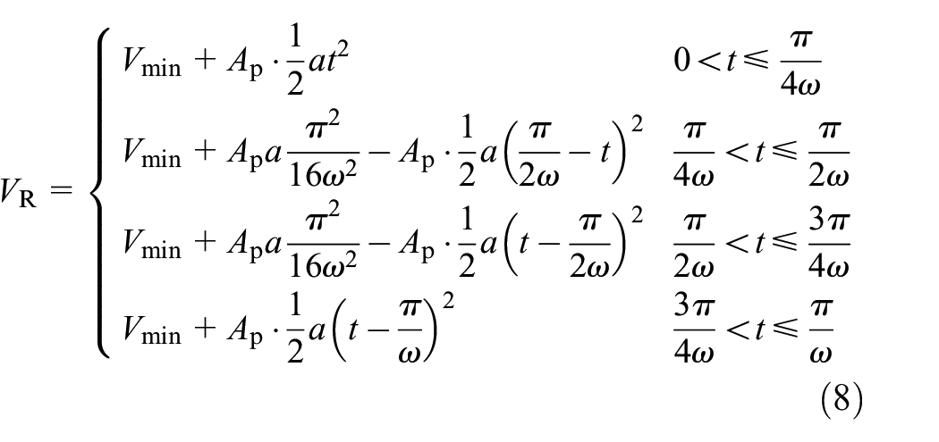
where Ap is the cross-sectional area of the 2D piston; Vmax is the chamber maximum volume; Vmin is the chamber minimum volume.
By differentiating equations (7) and (8) with respect to time, one can derive the rates of change of the left and right cavities over time, as expressed in equations (9) and (10).


As depicted in Figure 4, the schematic diagram elucidates the volume alteration within the pump chamber. A 2D piston pump comprises two piston chambers, each autonomously oscillating for oil suction and discharge. Concurrently, leakage arises through the clearance between the 2D piston and the cylinder body, thereby influencing the pressure within the two chambers. The instantaneous pressure within the left and right chambers can be characterized by the continuity equation, delineated in equations (11) and (12).32,33


where βe is the bulk modulus of the oil; pL is the left chamber pressure; pR is the right chamber pressure; VL is the left chamber volume; VR is the right chamber volume; QLoL is the leakage flow rate outside the left chamber; QLoR is the leakage flow rate outside the right chamber; QLi is the internal leakage flow rate, with positive flow rate indicating leakage from the left chamber to the right chamber and negative flow rate indicating leakage from the right chamber to the left chamber; QinL and QinR are the flow rates entering the left and right chambers from HP port and LP port, respectively, as described in equations (13) and (14).


The fluid zone of the 2D piston pump.
Q iL and QoL denote the flow rates entering the left chamber from the LP port and HP port, respectively, whereas QiR and QoR denote the flow rates entering the right chamber from the LP port and HP port, respectively. A positive flow rate signifies oil inflow into chambers, while a negative flow rate indicates oil outflow from chambers. This determination can be made employing the throttling formula, explicated in equations (15)–(18).
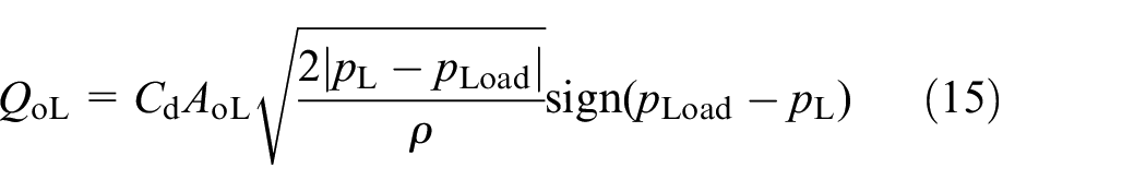


where Cd is the orifice coefficient; AoL is the communication area between the left chamber and the oil outlet; AiL is the communication area between the left chamber and the oil suction port; AoR is the communication area between the right chamber and the oil outlet; AiR is the communication area between the right chamber and the oil suction port; pLoad is the outlet load pressure; pT is the fuel tank pressure; ρ is the density of the oil.
As the rotation of the 2D piston remains constant and the axial contact length LgL and LgR between the piston and the flow window are defined by equations (19) and (20).


where Lg is the contact length of flow window; Lgmin is the minimum axial contact length; xp is the displacement of the 2D piston.
The radial contact length between the piston and the flow window progresses linearly over time. The variation in the communication area between the left and right chambers and the suction and discharge windows is delineated by equations (21)–(24).


As depicted in Figure 5, the 2D piston pump exhibits both external and internal leakage phenomena. The presence of a gap between the piston ring and the 2D piston can lead to oil leakage to the outer environment when there exists a pressure differential between the chamber and ambient pressure. Furthermore, as the 2D piston moves linearly, oil may also be carried outward due to shear flow. These forms of leakage are primarily characterized by laminar flow, predominantly consisting of Poiseuille flow and Couette flow. The leakage flow rates from the left and right chambers are detailed in equations (25) and (26), respectively.34,35

where QLoL is the leakage flow rate outside the left chamber; QLoR is the leakage flow rate outside the right chamber; μ is the oil dynamic viscosity; d is the 2D piston small diameter; Lpr is the length of piston rings.
The external leakage and the internal leakage.
The internal leakage of the 2D piston pump encompasses both axial internal leakage, denoted as QLia, and circumferential internal leakage, designated as QLir. Thus, the total internal leakage, QLi, can be expressed by the following equation (27).

Simplifications in the modeling of axial internal leakage were made by ignoring the impact of the flow window. Therefore the calculation method for axial internal leakage QLia is basically the same as that for the external leakage, as shown in equation (28).

where Lp1 and Lp2 are the two contacting lengths of the 2D piston; D is the 2D piston major diameter.
Circumferential leakage, denoted as QLir, denotes the leakage of the left and right chambers through the gap between the 2D piston and the cylinder body in a circumferential direction, as illustrated in Figure 6. However, this type of leakage presents a unique characteristic: in traditional standard leakage formulas, the length of the leak at its point of occurrence holds a certain scale. In the 2D piston pump, owing to its zero-opening design, the leakage length equals zero, rendering it incalculable by conventional leakage formulas. To address this, a specific approach is adopted, wherein this distinct circumstance is likened to oil flow through the valve port, and then compared with the leakage formula. Should the value calculated by the leakage formula exceed that determined by the valve port flow formula, the latter is adopted; conversely, if the leakage formula yields a lesser value, it is utilized for calculation, leading to the formulation of equation (29). 28

where Lr is the circumferential contact length between the 2D piston and the cylinder block, which can be determined by equation (30).


The 2D piston and cylinder block at rotational angles: (a) 0 deg, (b) 22.5 deg, and (c) 45 deg.
Interaction model
The mathematical model integrating dynamics analysis and piston chamber pressure is coupled to resolve, and the wear issue of the conjugate rolling pair in the 2D piston pump is simulated and examined. The requisite parameters for this simulation are outlined in Table 1.
Main parameters of the simulation.

Results and discussion
Simulation results
Figure 7 illustrates the fluctuations in pressure within the chambers of the 2D piston pump. Two noteworthy observations emerge: firstly, despite an external load pressure of 21 MPa, the chamber pressure surpasses this value. Secondly, when the left and right chambers are switching between suction and discharge (when the 2D piston rotates to 0°, 90°, 180°, etc.), there is a transition stage in the oil pressure. These two results will have an impact on the force of the cam, which has not been considered in traditional wear model.

Pressures of the chambers.
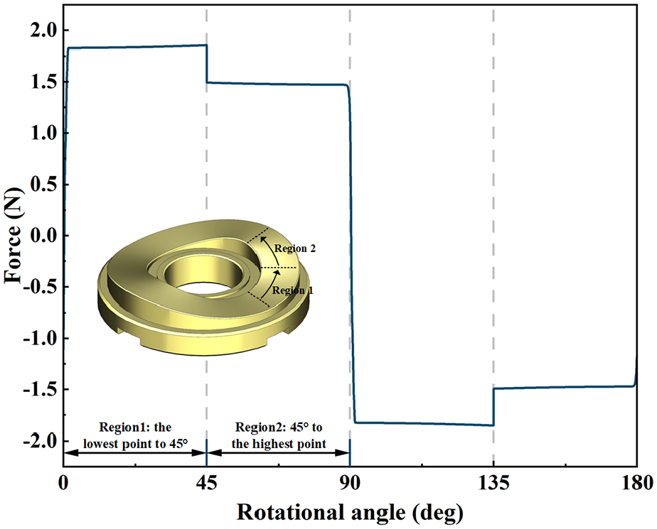
Based on the dynamic analysis outlined above, it becomes evident that during the operation of the 2D piston pump, the rollers and cams on both sides experience alternating frictional forces. Consequently, scrutiny needs to be focused solely on the support force and frictional force exerted by the cams and rollers from 0° to 90°. This approach facilitates the prediction of the wear position of the conjugate rolling friction pair.
Figures 8 and 9 depict the support force and friction force on the cam, respectively. Figure 8 reveals the presence of both positive and negative support forces. A positive support force indicates that the roller receives support force from the left cam, while a negative support force suggests support from the right cam. As the 2D piston rotates to 0°, the support force experiences a rapid shift due to the pressure transition within the cavity, potentially leading to impact marks on the cam surface. Secondly, it was observed that 0° to 45° and 90° to 135° are the most severely worn positions of the left cam and right cam respectively. Remarkably, theoretically, no wear occurs on the left cam from 90° to 180°. It can also be seen from Figure 9 that the left cam surface is worn in the range of 0° to 90°, and because of the pressure angle, the friction force also change slightly with the angle. Meanwhile, considering the chamber pressure analysis, there is a rapid transition zone in the force on the cam at 90° and 180°, which provides a more realistic representation compared to the abrupt force changes in the traditional wear model.

The supporting force of the cam.
The friction force of the cam.
Experimental validation
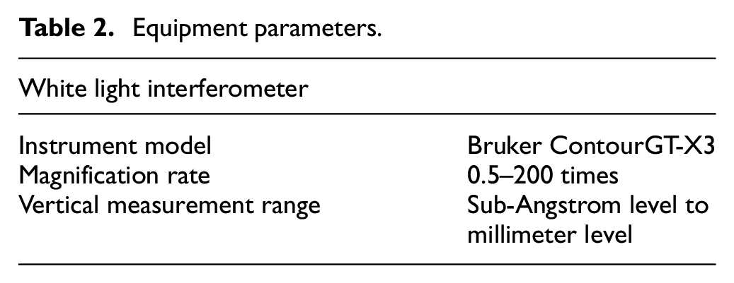
To verify the accuracy of the analytical model, the experiment employed a white light interferometer to analyze the rolling friction components after prolonged operation, and the specifications are detailed in Table 2. The experiment aims to detect wear at various positions on the cam and subsequently compare the extent of wear observed. Positions exhibiting significant wear will be juxtaposed against predicted locations derived from the theoretical model, thereby validating its accuracy.
Equipment parameters.
The experiment entails a surface inspection of the cam, illustrated in Figure 10. Seven regions exhibiting cam wear were selected for analysis, encompassing the three typical areas theorized to undergo wear: 45°, peak, and low point. These areas were deliberately chosen for repetitive examination to ensure the precision of the results.

Cam after long working time.
Figure 11 depicts the three-dimensional topographies of the cam surface, with the direction of the roller rolling clearly indicated. Upon examination of the figure, numerous small wear pits of varying depths are discernible in the wear area located at the low point and at the 45° position of the cam. Additionally, furrows are present in the wear area, albeit absent at the top of the cam. This observation suggests that wear is more severe at the low point and 45° position of the cam. Upon comparison of the wear at the three 45° positions in Figure 11(e) to (g), it becomes evident that wear is concentrated in the region where the roller transitions from the low point to the top, while wear in the area from the top to the low point is less severe. The test results outlined above align with theoretical analyses. A comparison between Figure 11(e) and (f) reveals differing degrees of wear in these two locations, indicating poor contact consistency between the two rollers and the cam, likely attributable to the asymmetry of the cam surface. Furthermore, rolling marks were observed in Figures 11(a)–(d), predominantly concentrated on the inside of the cam. This suggests that the roller may have derailed or tilted, temporarily departing from its intended rolling track.

Three-dimensional morphologies of the cam surface: (a) Bottom1, (b) Bottom2, (c) Top1, (d) Top2, (e) 45°–1, (f) 45°–2, and (g) 45°-3.
Figure 12 presents the outline data of the cam surface, with outline1 representing the vertical roller rolling direction and outline2 representing the roller rolling direction. Upon analysis, areas exceeding 0 μm can be deemed as wear debris accumulation. A comparison of the 7 selected wear areas reveals that the region with the largest wear depth is 45°−2 of the cam, with a maximum wear depth of 14 μm. Conversely, the area with the smallest wear depth is 45°-3 of the cam, where the maximum wear depth is only 8 μm. In conjunction with the roller’s shape, the wear patterns on the cam align with Hertzian contact theory. For instance, the curve shape of outline1 approximates a U-shape, exhibiting significant wear in the middle and similar wear levels throughout. Thus, reinforcing the cam to enhance the roller’s surface hardness from the low point to the high point is necessary, with the most severe wear occurring from the low point to 45°, which is completely consistent with theoretical prediction.

Surface profiles of the cam: (a) Bottom1, (b) Bottom2, (c) Top1, (d) Top2, (e) 45°–1, (f) 45°–2, and (g) 45°–3.
Next, we investigated the wear of a pair of rollers, as depicted in Figure 13. To ensure experimental accuracy, multiple areas around the circumference were selected for detecting roller surface wear. The two groups with the greatest difference were then selected and illustrated in Figure 14. Firstly, the wear observed on the roller surface resembles that on the cam surface. This similarity may be attributed to both materials being GCr15 steel, sharing the same processing technology, and having relatively similar hardness levels. Secondly, plastic deformation and material stacking occur on the roller surface, potentially leading to deviations from the preset trajectory and the appearance of rolling marks on the cam surface. Lastly, while the roller’s surface curvature is designed to be symmetrical to the center, the actual wear center deviates, and the most severe wear area does not coincide with the center of the roller surface.

Rollers after long working time.

Three-dimensional morphologies on the roller surface: (a) Roller1-region1, (b) Roller1-region2, (c) Roller2-region1, and (d) Roller2-region2.
Conclusions
Based on a 2D piston pump, this paper investigates the wear of its conjugate rolling friction pair through theoretical modeling and experimentation. Initially, the theoretical analysis incorporates variations in oil pressure within the two chambers to assess their impact on the load. A mechanical model of the conjugate rolling friction pair is then established to determine the friction distribution on the cam surface and identify areas susceptible to wear. Subsequently, experimental verification is conducted to assess the wear of a set of rollers and cams after prolonged operation. The findings are summarized as follows:
Both theoretical analysis and experimental results have confirmed that the cam surface exhibits severe wear across its entire range, with the area from the lowest point to 45° experiencing the most significant wear. Strengthening the surface hardness of the cam is deemed necessary.
Experimental tests reveal that while the wear pattern of the cam aligns with Hertzian contact theory, the wear of the roller deviates from theoretical expectations. Notably, the roller wear is characterized by off-center wear, inconsistent with its design specifications. Plastic deformation and material stacking on the roller surface are speculated as potential causes. Enhancing the surface hardness of the roller is recommended to ensure it surpasses that of the cam.
Despite theoretical predictions suggesting no wear from the highest to the lowest point of the cam, actual experimental observations indicate wear in this region. This wear is attributed to the preload force acting on the conjugate rolling friction pair, underscoring the direct influence of preload force magnitude on pair wear.
Through theoretical analysis and experimental investigation of the conjugate rolling friction pair, strategies for its improvement have been identified. Additionally, novel phenomena have been uncovered, such as rolling marks where the cam surface deviates from its intended track, suggesting a risk of roller derailment. Addressing these issues is crucial to ensuring the long-term operation of the 2D piston pump.
Footnotes
Handling Editor: Mohammad Azadi
Declaration of conflicting interests
The author(s) declared no potential conflicts of interest with respect to the research, authorship, and/or publication of this article.
Funding
The author(s) disclosed receipt of the following financial support for the research, authorship, and/or publication of this article: This paper was supported by the Joint Foundation of National Natural Science Foundation of China [grant number U2233212].