
Abstract
Unidirectional fiber-reinforced thermoplastic (UD) tapes are used increasingly in lightweight construction for local reinforcement of plastic parts. A critical step in UD tape manufacturing is spreading of the fiber rovings by mechanical, electrostatic, pneumatic, or acoustic means to obtain a homogeneous carpet. This is a prerequisite for homogeneous impregnation, which in turn is a requirement for defect-free reinforced components. A major challenge in fiber spreading is the inconsistent and scattering width of the fiber rovings within a bobbin or between different bobbins caused by the manufacturing process of the rovings. Especially for heavy tows – carbon-fiber rovings consisting of more than 24K filaments – variable input quality of the rovings renders obtaining a constant final roving width with existing spreading techniques impossible. We propose a novel spreading technique based on the principle of forced conveying that aims to provide constant final widths that are largely independent of the quality of the input roving. In a feasibility study, we investigated the forced conveying spreading behavior of a 60K carbon fiber roving; our new spreading method provided constant final widths independent of initial width and cross-sectional shape. Statistical analysis showed that both the wrap angle and the circumferential speed of the roller and their quadratic influences have highly significant effects on the final spread width. With an
Introduction
The goal of the European Union to become climate-neutral by 2050 1 calls for efficient technical solutions that reduce pollutant emissions. Unidirectional fiber-reinforced thermoplastic (UD) tapes contribute to climate neutrality: In composite components and local reinforcement of plastic components, they replace metallic counterparts and thus reduce weight and consequently emissions while maintaining the required mechanical properties.2–5 To produce UD tapes, multiple rovings (i) are unwound from a creel and aligned next to each other, (ii) spread to form a homogeneous fiber carpet, (iii) impregnated with a thermoplastic matrix, (iv) calibrated to a final thickness, (v) cooled and (vi) rewound, 6 as shown in Figure 1.
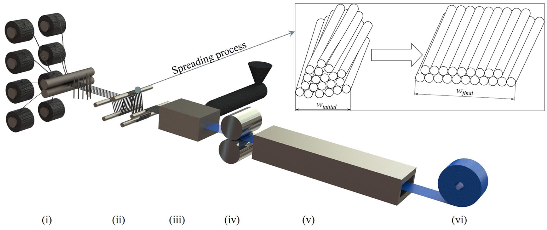
Schematic representation of a UD-tape manufacturing process with detail of the spreading process – where the rovings (i) are unwound from a creel and aligned next to each other, (ii) spread to form a homogeneous fiber carpet, (iii) impregnated with a thermoplastic matrix, (iv) calibrated to a final thickness, (v) cooled and (vi) rewound.
An essential step in UD-tape manufacturing is fiber spreading, which is critical to producing a high-quality tape. Only when the fiber rovings form a homogeneous (i.e. evenly distributed over the cross-section) carpet of filaments can a polymer melt penetrate them evenly and achieve proper fiber impregnation. A variety of fiber-spreading techniques based on various physical principles are available: For instance, fiber rovings can be spread (i) mechanically,7–12 (ii) electrostatically,13–17 (iii) pneumatically,18–25 (iv) by vibration,26–28 or (v) acoustically.29,30 These techniques have the common aim of spreading a fiber roving from an initial to a final width, ideally homogeneously (Figure 1), but they differ in the technical effort involved and in the cost of implementation in industrial production processes. 31
One of the simplest spreading methods is by mechanical deflection (Figure 1(i)), where fiber rovings are passed over a number of rods and the rovings widen at each deflection due to different tensile stresses acting on the filaments: “Outer” filaments, which pass the rod at a greater radial distance, experience greater stress than “inner” filaments, which are closer to the rod. To reduce stress, the outer filaments move to the center and displace the inner filaments, which consequently move to the sides.
A large number of deflections is required to spread a roving as shown in a previous work by Kohl et al. 32 This places the roving under high tension force, which, in combination with the deflections, causes single fibers to break and reduces the quality of the final tape as shown by Siegl et al. 33 Furthermore, spreading by deflection is commonly affected by a multitude of parameters, such as number of rods, rod diameter, rod immersion depth, horizontal rod spacing and roving take-off speed. 34 This renders controlling the process a complex task, in particular, if several rovings are processed at the same time. One major challenge in fiber spreading is inconsistent initial roving width after unwinding from the creel: A roving may exhibit partial folds or twists that are formed either during the production process or during winding onto a bobbin.31,35 For impregnation and, ultimately, high UD-tape quality, however, the fiber carpet must be homogeneously spread despite variations in initial roving width. To illustrate the fluctuations in roving width after unwinding from a creel, we measured the width of 1 typical 60K carbon fiber roving at 175 different positions. As Figure 2 illustrates, 50% of the measured widths are between 11.88 and 14.52 mm. The maximum width measured was 16.64 mm. By twisting or folding the roving in partial regions, the width can be reduced to 7.07 mm.

Box-whisker plot demonstrating the variation in initial roving width: The width of a 60K carbon fiber roving (Pyrofil TRH50 60M, Mitsubishi Chemical) was measured at 175 times different positions before spreading. Low values indicate tightly twisted filaments.
To address this problem, we propose a novel mechanical spreading technique based on forced conveying and present experimental results that confirm its ability to achieve homogeneous spreading largely independent of roving input width. We are also contributing to the lack of literature on this topic by providing an initial study on fiber spreading through forced conveying.
Spreading by forced conveying
Our new, patent-pending spreading system is based on the concept of forced conveying. Grooves with a triangular cross-section (a = h = 0.5 mm) are introduced into the outer surface of the spreading roller with a diameter of 45 mm, as shown in Figure 3(a). Starting from the center (pitch p = 0), the grooves wind symmetrically on both sides in a helical shape around the roller, with the pitch of the helical line increasing outwards such that the distances between the helices at the outlet are identical. Four sets of grooves, each with a peripheral angle of 30°, are evenly distributed around the circumference. In between, un-grooved areas act as relaxation zones for more gentle spreading of the roving. Each grooved region, which contains 50 grooves, widens from 50 to 60 mm from beginning to end. The starting width of the grooves was chosen so that we can process a multitude of commercially available rovings. In our case, we can ideally spread rovings with an initial width of 25 mm by a factor of greater than two. When the spreading roller rotates, the roving slides into the grooves, in which the geometric constraints separate bundles of filaments. The full spreader assembly is shown in Figure 3(b): A centering roller aligns the roving with the center of the driven downstream spreader roller, which is followed by two guiding rods. The first one forces the roving to wrap around the spreader roller and the second one acts as a stabilizer for the inline width measurement; the latter is explained further below. The wrap angle at the spreader roller can be adjusted by its vertical position.

Schematic representation of: (a) the grooved spreading roller and (b) the spreading setup.
This novel spreading configuration allows variable and categorical parameters to be set to control the spreading. The former include circumferential speed of the roller and wrap angle of the roving, while the latter include direction of rotation, number of grooves, groove pitch, groove shape and roller diameter.
Experimental
The new spreading system was investigated in experiments using our novel authentic test rig (Figure 4) and a 60,000-filament carbon fiber roving. The roving was unwound from a roving spool by a speed-controlled winder and pulled through the spreading setup. The roving width was recorded both in its initial and final states (i.e. before and after spreading) by two monochrome line-scan cameras (Alkeria N4K-3-C). Using rotary encoders, the recording frequency of the cameras was adjusted and synchronized with the roving take-off speed such that the same section of the roving was recorded both before and after spreading. Each measurement recorded a roving segment length of 94.25 mm – one revolution of the roller on which the encoder was mounted. From these recordings, the initial and final widths were then determined using a Python script to apply image-binarization and edge-detection algorithms and calculate the average width over the measured roving length sample of 94.25 mm. Load cells enable direct measurement of the roving’s tensile force both before and after spreading, regardless of the specific spreading setup used.

Schematic of the spreading test rig.
In a feasibility study, we tested whether the new spreading system produced a homogenous carpet independent of the initial roving width. In addition, we investigated the parameters that influence the final width. To this end, we used a central composite design (CCD) in which both the circumferential speed of the roller and the wrap angle were varied systematically, which resulted in a 2² design plus five central point replicates and four axial points. The corresponding level settings are shown in Table 1.
Level settings of the experimental design.

As part of this feasibility study, 35 measurements on the same roving at 1-min intervals were performed using the same settings for both the conventional spreading technique by deflection (Figure 1(i)) and the new spreading system based on forced conveying (Figure 3(b)). In the following these measurements are referred to as samples. For the conventional spreading setup, five 15 mm diameter spreading rods were positioned in the test rig in a zigzag arrangement with a spacing of 50 mm and an immersion depth of 40 mm. The width of the roving was recorded before the first rod and after the last rod. In both cases, the drive pulled the roving through the spreading setup at 2 m/min. In the new system, again at 2 m/min, the spreading roller turned in the opposite direction to the roving take-off, and the wrap angle of the spreading roller was set to 80°.
Results and discussion
Figure 5 illustrates the results of the feasibility study. In the case of the conventional spreading technique (Figure 5(a)), the trend of the initial roving width is reflected in the final roving width: the final width after spreading directly correlates with the initial width before spreading. Further, the standard deviation is even greater after spreading than before spreading, increasing from 0.83 to 1.05 mm. At 6.36% and 6.27%, respectively the relative standard deviations (RSD) of the initial and final widths are close. In contrast, the forced-conveying principle (Figure 5(b)) clearly provided more uniform final roving widths despite large variations in initial width. The standard deviation improved from 1.20 to 0.43 mm; more specifically, the RSD decreased from 8.86% to 2.38%. When looking at the measured forces acting on the fiber rovings, we could see that the filaments are exposed to significantly lower forces. When spreading by deflection, we achieved a tensile force of 120 N on the rovings. In comparison, when spreading by forced conveyance, the force is only 10 N, which corresponds to a reduction by a factor of more than 10.

Comparison of initial and final widths for: (a) conventional spreading by mechanical deflection and (b) spreading by forced conveying with a grooved roller. The circles and squares represent the evaluated initial and final roving widths, respectively. For both curves, the solid lines mark the mean width, while the dashed lines indicate a process window of twice the standard deviation of the 35 measurements.
A factorial analysis of the measured data showed that the wrap angle had a positive effect on the final width after spreading: The final width increased with increasing wrap angle. The circumferential speed did not affect the final width. Analysis of variance (ANOVA) at a 5% level of significance confirmed these results. The wrap angle effect is highly significant with a p-value of less than 0.0001 and a high F-value of 762.82. The circumferential speed is insignificant with a p-value of 0.1349. ANOVA also confirmed that the interaction between the two factors is insignificant at a p-value of 0.6088. Initially it seemed that a linear regression model captured the behavior of the spreading process well. This was also confirmed by the model quality, with a coefficient of determination
A polynomial analysis was carried out to identify non-linear effects. A sequential model fit (ANOVA type I analyses) was performed to determine the highest significant polynomial degree without unnecessarily increasing model complexity. Table 2 shows a summary of the sequential model fit. In addition to the linear polynomial, only the quadratic polynomial has a significant p-value where the lack of fit is not significant. Therefore, the model was extended to include quadratic terms for further evaluation.
Fit summary of the sequential model fit.

Figure 6 illustrates the effects of the main influencing factors. The wrap angle (A) had a positive effect on the final width after spreading: The final width increased with increasing wrap angle. Circumferential speed (B) also affected the final width, but to a much lesser extent. ANOVA at a 5% level of significance confirmed these results. The wrap angle effect is highly significant with a p-value of less than 0.0001 and a high F-value of 2781.16. The circumferential speed is significant with a p-value of 0.0131. ANOVA also confirmed that there is no significant interaction between the linear and quadratic effects of the factors (A²B, AB²), while the quadratic effects of the factors are highly significant. The quadratic effect of wrap angle (A²) is significant with a p-value of 0.0071, as is the quadratic effect of circumferential speed (B²) with a p-value of 0.0302. The central points show a high repeatability; further, their means lie exactly on the black line that indicates the values predicted by the model. Figure 6 also shows that the axial points at the edges of the experimental design are very well taken into account by the quadratic model. In other words, a quadratic regression model captured the behavior of the spreading process well, and there were no missing inputs due to an insignificant lack of fit. The larger confidence intervals at the edges of the axis section shown are due to the fact that extrapolation takes place outside the axial points (outer red points).
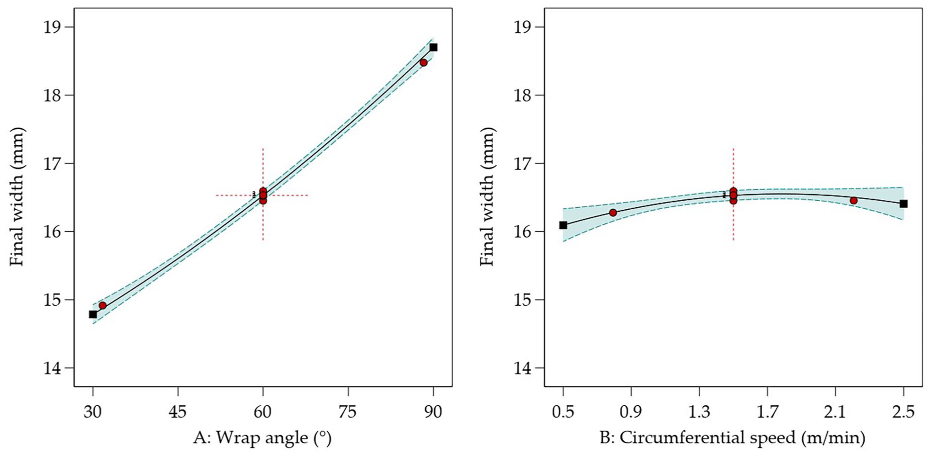
Main factors influencing the final width, where the red dots at the red dashed cross represent the central point measurements and the red dots further out represent the axial points. The square model is represented by the solid line and the green dashed line represents the 95% confidence interval (CI) bands.
Figure 7. shows surface plots of the regression models. Figure 7(a) illustrates that the model predicted both the factorial and the central test points well. This is also confirmed by the model quality, with a coefficient of determination

where

Surface plot of the regression model with (a) the factorial and central points and (b) including the axial points.
Constants of the quadratic model equation (1).

In Figure 7(b), the axial points are added to the plot. Within their expected error margins, all of these are predicted well by the model. This, again, confirms the validity of a quadratic regression model.
Conclusion and outlook
We have presented a new, low-cost spreading technique for fiber rovings. The system is based on a forced-conveying principle that uses a grooved spreader roller surface with strategically positioned relaxation regions. Using only a single spreading roll, this new approach significantly reduces the tension force acting on the fibers, provides gentler spreading of the roving and decreases the complexity of process control because fewer parameters affect the spreading process than in conventional deflection-based methods. In addition, minimizing the number of deflections helps to reduce fiber breakage as reported in 33 and thus improves the overall integrity of the material. A limitation of this setup is the need for precise centering: the roving must enter exactly at the center of the spreader roller to avoid it being pulled to one side.
We have demonstrated that this new spreading technique reduces considerably the impact of initial width variations on the final width after spreading, dramatically improving roving width consistency for downstream processing. A central composite design targeting the final width revealed that the wrap angle of the roving around the roll and the circumferential speed of the roll and their quadratic effects are the main influencing factors. In contrast, both the interaction between wrap angle and circumferential speed and the interaction between their linear and quadratic effects have no significant influence on the final width. The quadratic regression model obtained allowed reliable prediction of the final width.
As part of future work, the technical design needs to be optimized to improve roving centering. In addition, tests should be carried out with a changed direction of rotation and alternative groove arrangements.
Footnotes
Declaration of conflicting interests
The author(s) declared no potential conflicts of interest with respect to the research, authorship, and/or publication of this article.
Funding
The author(s) disclosed receipt of the following financial support for the research, authorship, and/or publication of this article: This work was supported by Johannes Kepler University Open AccessPublishing Fund and the Federal State Upper Austria. The authors acknowledge financial support from the COMET Centre CHASE, funded within the COMET − Competence Centers for Excellent Technologies program by the BMIMI, the BMWET and the Federal Provinces of Upper Austria and Vienna. The COMET program is managed by the Austrian Research Promotion Agency (FFG).