
Abstract
The aim of this work is to find a suitable reinforcement in terms of mutual compatibility, surface microstructure, and mechanical properties of the resulting carbon composite parts. Two types of samples in layout + 45° / 0° / ± 45° / 0° / −45° and + 45° / 0° / −45° with a total thickness of 1.8 mm, wound on a rounded polyurethane core from several carbon rovings, were experimentally tested in the area of low elastic deformation up to 1 mm. In order to obtain basic engineering constants the tensile tests of whole parts failure have been carried out. Subsequently, several material and numerical models were developed in order to describe the problem of composite tensile loading. The model was solved by two approaches, specifically a layered shell and a layered solid. Considerable differences have been found in the properties of the real (experimental) and theoretical model based on the declared properties of the individual components. Probably due to the manufacturing imperfections and the porosity in the resulting material, the values of the basic engineering constants of the laminate of the resulting laminate reach lower values. This had to be solved by adjusting the material model of the used dispersion and matrix. The real arising failures were described by using the failure criteria for several time steps of the model solution and compared to the real experiment with quite good agreement.
Introduction
The global development of carbon composite materials has been the focus of study in companies and research institutions. In comparison to metallic structures, wound composites offer some unique engineering properties while presenting interesting but challenging problems for analysts and designers [1]. When replacing conventional materials by composites it is important to know the exact mechanical properties, because only with an appropriate combination of angles and stacking sequence through individual layers and optimal ratio between the dispersion and matrix it is possible to achieve solution tailored to the specific application. For this reason, the use of modern CAE technologies is the key point in the design of composite parts as mentioned in the study of Gay [2].
Generally, the carbon composite materials are tested for the bending strength and toughness, but the major problem of a lot of worldwide authors is, how to determine the tensile strength. The problem with tensile load is mainly due to the extremely high strength of fiber filaments and structural fragility of the thin walls of the formed profiles. Therefore, indirect methods based on the determination of the resonant frequencies or the conversion of values obtained e.g. with bending test are usually used [3] to determine the Young's modulus. According to Camanho et al. [4], the mechanical testing can be simplified by testing of simple structures, such as flat coupons. Wang and Kam [5] disagreed with this; they mentioned that the laboratory samples and real parts show considerable differences in the obtained mechanical properties. During the production of a composite part, it is necessary to consider a lot of aspects (grease, pressure, temperature, imperfect vacuum, porosity, real thickness of plies) and all this significantly affects the final mechanical parameters. Khoathane et al. [6] studied the tensile properties of composites with natural fibers and found out that based on the rule of mixture (ROM) predicted and the experimentally determined tensile strength are close to each other.
In general, [6,7] stated that the Young's modulus of the composite materials increased with the increase in the fiber weight ratio up to a certain amount (50–70%) and then fell down in a sudden break point. Vuure et al. [8] mentioned that the maximum potential for increasing the tensile strength is possible to be achieved with the plain woven or aligned long fibers rather than randomly oriented. Another very important parameter is the mutual hydrophobic properties at the interfacial bonding between matrix and dispersion [9], whereas for the synthetic fibers, the interfacial bonding is usually very good, but for the natural fibers and resins the poor adhesion is the main problem. Therefore, it is problematic to use natural fibers instead of the glass or carbon dispersion [10].
The objective of this work has been to analytically study and experimentally verify the basic mechanical parameters, especially the tensile properties of the wound tubes, created by various carbon materials from several manufacturers. The basic parameters have been analytically determined and then experimentally verified. A numerical model of the entire process of tensile loading, including the prediction of arising failures (described by the Tsai–Wu criterion), has been compiled.
Materials and methods
Nowadays, technologies like winding of fibers, tape wrapping, laminating of fabric layers, and other operations are often used for manufacturing of the so-called advanced composites [11]. Winding is a manufacturing process of rotational wrapping of several filaments from spools with simultaneous movement of the mandrel in the axial direction (Figures 1 and 2). That should keep the fibers continuous and aligned throughout an entire part [11,12]. Methods based on epicyclic winding or helical wrapping are generally used for manufacturing of thin-walled composite parts with circular or oval profiles [13,14]. Mertiny et al. [15] described designing of parts with multi-angle layups as a complex task, where the proper winding angles as well as stacking sequence need to be determined. The winding method is possible to be used for manufacturing parts with curved shapes and fluently changing cross-sections [3,16]. Those kind of methods are usually used for the so-called “wet” form, when the bundle of dry placed fibers is impregnated with resin subsequently in the mold. The “wet” wound carbon tubes have been used as the composite parts in this study.
An example of the winding principle. (a) Samples of wound tubes, (b) detailed in section cut.

Description of the material used for the production of composite tubes
Carbon rovings were used in total from three vendors. The basic fiber is carbon, the weight of the roving is the same for a given number of elementary threads (24 K or 48/50K), and the materials differ by the so-called sizing of their compounds. Sizing can also affect the appearance, touch, and workability of the roving.
Specifications of the wound tubes.

Each series of five pieces of cores was wrapped, and then successfully plugged into the polyurethane (PUR) matrix. Then the internal composition and structure of the resulting composites (reflection electron microscopy (REM), image analysis) and tensile tests were evaluated. H- and J-series contain the same fibers, but J-series contained fewer threads, and after fusion, small bubbles were found in the structure.
The optimal winding angle for tensile, compressive, and bending loading is found to be equal to α v = 0. It means the loading should act in the fiber direction. However, in real cases it is also necessary to consider the torsional load. Petru et al. [16] and Misri et al. [18], who used some advanced numerical criterion functions looking for the maximum value of the stiffness matrix, have dealt in a complex manner with this task. The agreeable conclusions of their work was the determination of the stationary point in the given equations, where simply the quadrant of the sine is equal to the quadrant of the cosine = 1/2. Based on this idea it is possible to find the value 45°, and respectively 135°, 225°, and 315° as the optimal winding angles for torsion loading. To verify this fact faster, it is possible by using optimization algorithms based on, for example genetic algorithms, which could find the fitness function value of such a trivial task in a very short time. The mathematical algorithm applied for generating the individual design points could be done according to Price et al. [19] and about their possible application to the composite materials, which could be read in Kulhavy and Lepsik [20]. Mokhtar et al. [21] also mentioned that for the ±45° angle the wound kenaf/epoxy tubes have the best compressive strength.
Testing of the manufactured tubes
Series of composite cores (PUR core, wrapped with carbon roving 24K (six layers) and 45–50K (three layers, PUR matrix BASF) were tested:
– Workability of the material: assessment of quality change of material during normal handling (fast); – Compatibility of matrix to the fibers: evaluation based on images from the image analysis by scanning electron microscopy (SEM); – Mechanical properties.
Workability
Carbon fiber (CF) rovings from three suppliers were used. Roving linear density is the same as the given number of filaments (24K or 48 / 50K). The materials differ in the so-called sizing–finishing mixtures of substances, which should ensure future affinity matrix to roving. The sizing may affect the look, feel, and workability of given roving. This assessment is subjective and based on personal experience in working with this type of fiber.
In terms of processing properties, the best one was roving 24K Toray where elementary fibers are uniformly distributed in the roving, and roving dimensions (width and thickness) remain constant and roving itself is compact even when working with material in short-term stress with virtually no volume corruption. The second best was roving 24K TENAX—for short-term stress does not violate the fiber bundle, a negative changes the roving dimension (width and thickness)—roving narrows the elementary fibers dividing them into smaller bundles and roving consequently does not cover the estimated surface. The material has a pronounced tendency to create a false twist. For the material TENAX 48K the situation is similar. The last evaluated is 50K ZOLTEK roving. With mechanical stress, the roving breaks down into sub-bundles of filaments, the roving narrows, and the number of broken fibers is negligible.
Fiber matrix compatibility
REM images from all series were selected to evaluate the compatibility between matrix and fibers. Samples were taken from each series from the same tube locations so that the images could be compared. The flaw is a crack or air bubble in the mass of the composite. Cracks in which the bare elementary fibers that protrude from the matrix are seen are extracted from it. All the described defects lead to impairment of the mechanical properties of the resulting composite [5,22]. Several samples of various surfaces were made for each series.
Series H and R were without bubbles and defects. There is good compatibility between the fibers and the matrix. Figure 3(a) of J-series shows good fiber–matrix compatibility. Material structure was free of bubbles and defects in the composite. The composite (Figure 3(a) and (b), right part of figures) and polyurethane core (left) composite interfaces are scanned from different locations of the composite. In S-series, minor defects in the composite can be seen including poor saturation, and the matrix does not crawl to the core. The highest number of defects in the composite mass and the very poor seepage of the fibrous layer are shown by T-series.
(a) Example of bubble-free composite – J-series surface image; (b) example of composite with flaws – Image of the surface in T-series.
Tensile test
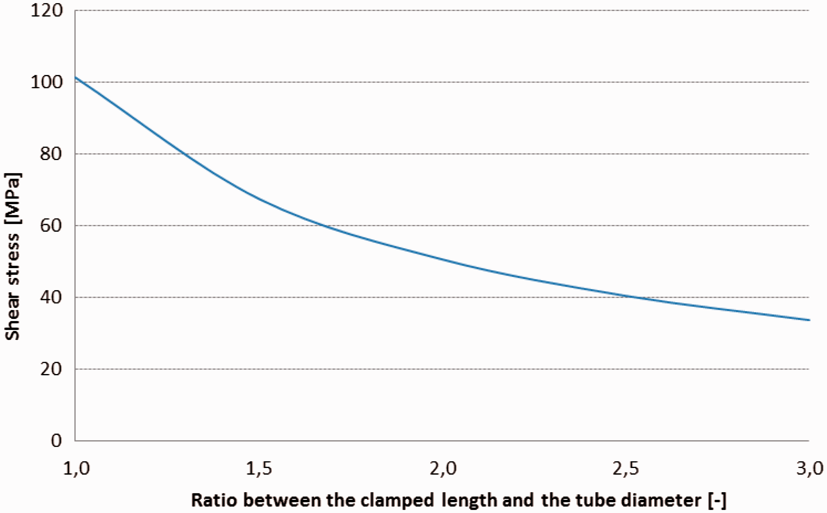
The tensile test was done for all the tubes. To create the “real” material models (section “Model”) it was necessary to obtained data from the experiments. Before the test, the tubes were fastened to the tensile machine as shown in Figure 4. Anchoring of the tube specimen is the biggest problem when testing the mechanical properties of thin-walled profiles [23]. The axial force for tube rupture may be up to 50 kN so specimen anchoring to the clamps has to be excellent. Traditional clamping jaws fail because the tube is very fragile in the cross direction and they could simply destroy the specimens. A new method of clamping was designed. The end portion of the extruded PUR core was removed from the tube and the composite layer was glued to the metal jaws (Figure 5). Of course, success of this principle depends on the suitable glue selection and therefore several types of epoxy glues have to be tested. It has been done based on the computed stress within the estimated values of maximal force and various ratios between the clamped length of the tube and the middle tube diameter as could be seen in Figure 6. Based on the obtained results, the glue Cyberbond CA 2000er and clamped length L = 1.5 × D
m
= 60 mm were chosen. For a better saturation of the glue throughout the entire connected surfaces, the clamping jaws were created by two bolts fastened semi-cylinder parts. The glued joints can be disassembled after the test by heating the jaws and the jaws can be used for the next test [2,24,25].
The clamped tested piece D40_1.8 mm, Lp 400 mm, and the tensile testing device. The scheme of the tube clamping. Required shear stress in the glued layer dependent on the L and D ratio.

Based on the results of the tensile modulus, it was found that the best values were obtained in H-series, followed by S-series as could be seen in Figure 7. Even if the S-series samples had the smallest fiber volume ratio and the composite masses, there were defects. Samples of H-series showed higher modulus values, even if they were the same type of material, with only half K and double number of the layers. For samples of T-series, there was a presumption of high values of the modulus with respect to their price and parameters of the elementary fiber guaranteed by the roving manufacturer. It could be even possible to achieve higher values by modifying the technology or by changing the matrix. This suggests that the potential of Toray is not fully utilized.
Tensile modulus of all the tested series.
The Tenax fiber series, which were well engaged, achieved average results compared to a series of Toray-containing fibers that had a defect in the structure. Before the casting, the Toray filament achieved the best results, but after being embedded in the matrix, they exhibited either moderate or worse results that were most likely due to defects in the structure. Although these were the most expensive fibers, the resulting composite was not without defects.
Theory of failure
A damage mechanism of composite with continuous endless fiber f, which is wound around the geometry of the core connected by a matrix m, is a complex analytical problem difficult to be described. The composite strength depends on the properties of individual components, which form a compact structural system. Properties of the fiber composites significantly affect the fiber orientation relative to the loading direction [26,27], whereas the metal materials show one failure mode i.e. cracking, and composites could exhibit one or combination of several failure modes, including fiber rupture, matrix cracking, delamination, and interface debonding [28,29].
Suriyati and Mertiny [15,30] studied the damage mechanisms of wound tubes. It was found that the failure modes strongly depend on the applied stress ratio, and the matrix damage can be minimized using [±30, ± 602] plies angle configuration. On the other hand, configurations of [±45, ± 602] and [±30, ± 602] showed higher functional and structural strength. The study of Bai et al. [31] focused on the mechanical behavior of wound tubes [±55] in a pure tensile loading, and it was observed that the matric cracks occur perpendicular to the tensile direction and microcracks are propagated around the fiber bundles.
The Tsai–Hill criterion was one of the created model. This is probably one of the most widely used currently (Figure 8; where index L indicates longitudinal and T indicates transversal direction). This interactive criterion is based on an idea to create a general theory of anisotropic damage. It is designed as a polynomial surface in which the area of damage contains only stress components. In his work, Capela et al. [32] claimed that the Tsai–Hill criterion could sufficiently predict the loading effect on the static strength of the specimens. With deep study of the two basic Tsai–Wu and Puck criterion, Emiroglu [33] in his work mentioned that the Tsai–Wu failure criterion is a simple criterion that takes into account the interaction of stresses in different directions by making use of the strength tensors. This could be seen in Figure 19 with the illustrated areas of the model results. It is possible to watch the similar trends like in the experiment for the individual steps of the jaw displacement. In layman's terms from “improbable failure” up to the moments,the part failure is almost “sure”.
The area of Tsai–Wu polynomial [34].
Model
The most effective replacement of conventional materials by composites is possible only with the appropriate combination of manufacturing technologies, stacked up of individual layers and optimal ratio between the dispersion and matrix, interface properties, cohesive forces, and failure criteria. For this reason, use of modern CAD technologies is the key point in the future of design of composite parts as mentioned in the study of Gay.2 Advanced methods could describe the entire damage process from its initiation to a complete failure of a composite structure [35–37]. Numerical analysis allows us to derive the different strain energies stored in the material directions of the constituents of composite materials [22]. An unanswered question is, how accurate the simulation should be to be suitable, i.e. the mesh relevance, chosen formulations, failure criteria, etc., when we consider the initial error caused by the material model and boundaries [38].
In our case, the models have been compiled in two possible ways. The first was as a layered shell (Figure 9(a)). This method should be easier and faster for the convergence of solution. In the case of the shell models, the production of the layered model is easier, because by using the conventional FE solvers, it is possible to simply define the shell – the base neutral surface and relatively to the surface define the other plies based on known material properties, where angle and thickness could be simply defined.
The two basic used approaches of the layered models creation: (a) shell; (b) solid part.
The second created case was a solid model, with separated individual layers with physically existing thickness as could be seen in Figure 9(b). This approach is used especially with regard to the subsequent post processing, when it is possible to study the interlaminar stress more accurately. For the solid model, it is necessary to create model of separated individual layers (with defined thickness and fixed position) and in the model setup, define the mechanical properties individually for each of the meshed “annulus”. These two approaches can be referred to in the study of Rolfes et al. [39] who had studied the 3D stress in composite parts using solid plates and shells.
The created mesh of solid part was mapped according to the two faces of the rod, with edge size of 4 mm, using the sweep methods with quadrilaterals elements with final 1275 nodes and 1250 elements.
Two types of layered model, one created from 6 plies and second from 3 plies (according to the layout in Figure 10), such as in the case of the experimentally tested parts have been created.
Layouts of the two carried models: (a) −45 °/0 °/45 °/−45 °/0 °/45 °; (b) 45 °/0 °/−45 °.
In all of the conducted models, the three basic types of helical fiber references 45°/0°/−45° (Figure 11) have been used. All elements laying on the parts have been guided by the cylindrical rosette in order to reach the solution. The main “zero” direction is parallel to the axis of tube rotation, in our case Z-axis of the global coordinate system. The task was solved as static with the rods remotely clamped from both face sides. At one with 0° DOF and at the second with the tabular defined displacements in the Z directions with four time steps. The best way to find the arising stress was to compute the force in the clamped parts of tube and then based on the known area of the cross section just determine the resulting tensile stress [40].
The analysis of the reference fiber angles.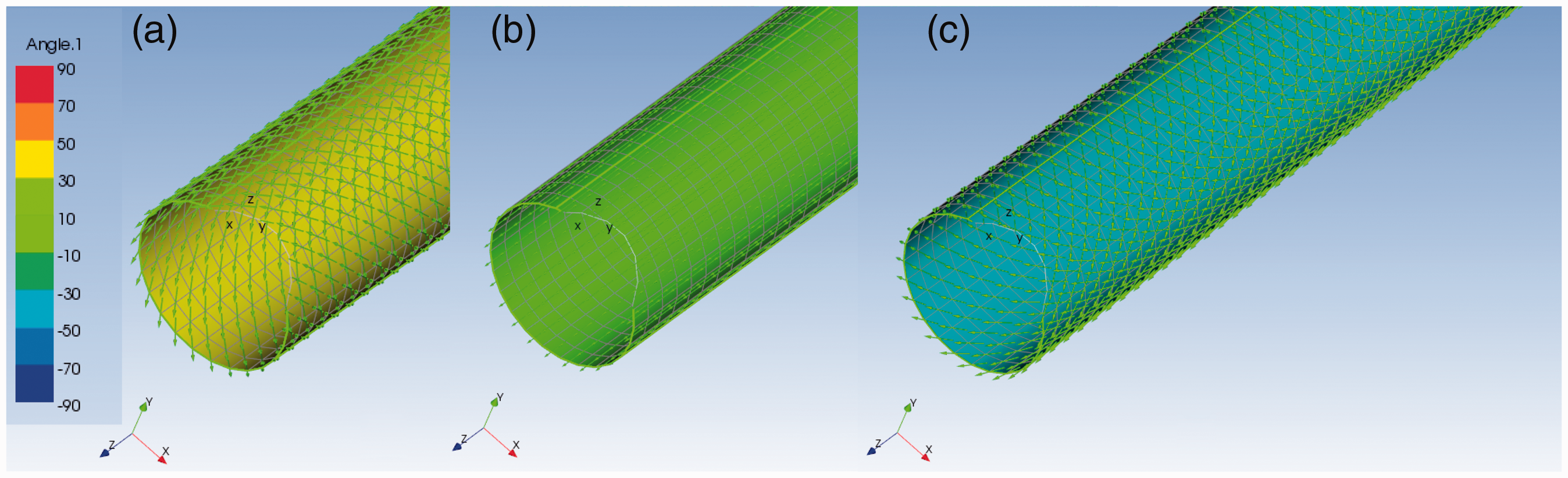
As it has already been mentioned, unlike for the conventional materials, the mechanical properties of the manufactured composite parts are always different from the properties of the base material. Therefore, it is difficult to set the constant values using the analytical models with sufficient accuracy. In the past, some of the constants have often been neglected or additionally obtained through measurements [7,9]. Over the time, it was possible to observe expansion of the analytic models and a comprehensive approach for obtaining all the elastic constants through the following models: phenomenological models, semi-empirical models, homogenized models, elastic-elastic model.
For anisotropic composite materials, the stiffness matrix is directly dependent on the main engineering constants. In the classical mechanics application of the Hook's law (1) generally in our case orthotropic (transversally isotropic) material in a rectangular coordinate [40]. Consequently, the stiffness could be described by a set of five parameters: Young's moduli (E11 and E22), Poisson's ratios (ν12 and ν23), and shear modulus (G12). With the help of homogenization techniques, these five parameters describing the stiffness behavior of the composite can be derived [2,5]. In the Cartesian coordinate system it is possible to obtain relation for the so-called ABD (marked just as C) stiffness matrix. The individual directions are the fiber marked as 1, normal to the fiber direction 2 and the last one 3 is normal to the surface of vectors 12


The transcription of the stiffness matrix to the shape of the engineering constants will then be (3)

Because there is a combination of several plies with various winding angles, it is necessary to transform the stiffness matrix of each ply by using the following equation

The theoretical values of the basic engineering constant after counting of the individual transformed stiffness matrix for the two cases of layered rods are in polar graphs as shown in Figure 12. Talbot and Woodhouse [41] has tried to describe, whether the laminate theory could be inverted in order to obtain the ply properties directly from the experimental results, whereas for conventional parts and materials it is possible, but in the case of wound composites, it is problematic because the material properties in the final parts always differ from the base materials due to a lot of imperfections in the mutual fiber overlapping.
Theoretical mechanical properties of the wound parts with the specified plies – layout: (a) Tenax – 6 plies; (b) Zoltek – 3 plies.
So the further used title “theoretical model” means model with the same boundary conditions and other attributes of the established task, apart from the material model. In the theoretical model, the basic material constants and members in the stiffness / compliance matrix are set based on the values declared by the material manufacturers, analytical models working with material technical sheets or on the globally used values typical for this kind of materials in conventional parts (books, impacted articles, material libraries). The main problem in using the winding technology is that the final mechanical properties are always different from the same part with exactly the same measurable characteristics like volume, mass and the inner plies layout, and stacking sequence. For comparison of the conventional and wound parts, please refer to Kulhavy and Lepsik.3,20
Results and discussions
The first models based on the theoretically declared properties were significantly different from the data obtained from the experiment. Therefore, it is possible to say that by using the standard analytical methods it is not possible to directly describe the properties of the wound parts the reason being that the inner fibber structure is not perfectly aligned, which is one of the fundamental postulate in all of the mentioned methods. Therefore, in the results the three individual quantities are mentioned:
– Theoretical model (based on the known properties and conventional analytical methods); – Real model (some of the engineering properties were fitted according to additionally conducted experiments); – Experiment (the real values measured on manufactured parts).
This could be caused especially by some manufacturing inaccuracies and a number of bubbles in the matrix as had been mentioned in the “Materials and methods” section. So, it was necessary to adjust the material models. The results of the experimental data in comparison to the theoretical model and model with the real found values could be seen in Figure 13 for the 6 plies Tenax serie H, and Figure 14 for the 3 plies Zoltec serie R.
Results of the 6 plies shell. Results of the 3 plies shell.

The experimentally found values of E1 are as follows:
6-plies shell = 120 GPa, 3-plies shell = 145 GPa, 3-plies solid = 120 GPa.
As another possibility, the models consisting of solid bodies with real thickness have been created. As could be seen in Figure 15, there are some measurable differences so it is possible to say that the two approaches—shell or solid—are not equal, even if they theoretically (analytically) should be. Generally, use of the shell models has been developed in order to simplify difficult task, reduce the required time, and improve the convergence. From the point of view of the fundamental analytical solution based on Hooke's law, the obtained results should be the same. However, in some parts, with complicated shapes it is possible to find differences in the results obtained by the shell and solid model, caused by simplification of the solved geometry. For simple parts like in our case for the straight tube with constant diameter and thickness, the basic stiffness matrix should be the same in the both cases. The only difference is in the normalized stiffness matrix where the integration of the thickness going through the curved neutral surface varies. Probably, in the case of solid element, the surface curvature through the defined thickness is integrated to the neutral surface and in the solid case relatively to the real plies layout, and that is the place, where the difference arises. It means that the error caused with the shell simplification would theoretically increase by increasing the thickness.
Comparison of the created shell and solid models.
Our results agree with Khoathane et al. [6] and Ku et al. [7] who also mentioned that the main problem in the prediction of the tensile properties of fibre composites by modeling based on the base mechanical properties of used matrix and dispersion is giving too optimistic values.
The phenomenon of solid-shell inequality is considerable also with the higher values of the fibers modulus of elasticity, as could be seen in Figure 15, whereas with the lower values of E1, the results for shell and solid are almost the same, and with the higher (theoretical) values, declared by manufacturer, significant difference could be seen. It means that the inequality is more obvious not only with the increase in the thickness but also with the increase in the Young's modulus.
In Figure 16, it is possible to see the inner stress in the two types of the modeled rods—with 3 and 6 plies.
The values of arising stress through the sample thickness in the 1, 2, 3 directions of the model with: (a) 6 plies; (b) 3 plies.
Failure results of samples
The tests were conducted also up to the total destruction of the created 3-plied rod. As could be seen in Figure 17, there are several almost linear sectors on the way to the final rupture. It was possible to observe several arising deformations during the loading like local cracks, small delamination, and filaments rupture (Figure 18). For the carried experiment, also the above specified numerical model has been enhanced and solved.
Force–displacement dependency. The place of the final rupture. The value of Tsai–Wu failure criterion in the solved model during the individual steps of the model solution.


As could be seen in Figure 17, the resultant force in the simulation with layered solid model is still rising up highly above the place where the real part was destroyed and then the model lost convergence. Unlike for conventional approaches, it is not possible to simply define a value of definite strength limit or nonlinear plasticity. For this purpose, as has been described in the “Theory of failure” section, the so-called failure criteria exist for predicting the failures in the composite parts [42–44]. The examples of the 3-plied tube failure are given in Figure 19 for the five created time steps of the model solution. In comparison with the experimental measurement above, it is possible to say that the prediction of the failure is in a good agreement.
Conclusion
From the results of the Young's modulus, it was found that the best results were achieved in H-series (6 plies), followed by S-series (3 plies). S-series obtained very good results even though they contained several inner defects (wrong compatibility matrix with fibers) and have relatively low the fiber-to-volume ratio. Here, stronger roving was used in production, but it is not possible to say whether this could cause these defects. The highest number of defects in the composite mass and bad compatibility between matrix and fibers is shown by T-series. When the fibers are entangled through the matrix, there is larger volume of air and, consequently, can cause deterioration in the resulting mechanical properties.
For samples of T-series, there was a presumption of high values with respect to the price and parameters of roving of the elementary fiber guaranteed by the manufacturer. As has been revealed in our tests, it might be possible to achieve even better results by modifying the technology or by changing the matrix. This suggests that the potential of Toray has not been fully utilized.
The series containing Zoltek fibers after being embedded in the sample matrix were free of defects, and the results of the measurements were comparable and better than the other series. If we compare the series containing Toray fibers (six layers with defects, the most expensive fibers) and the series with Zoltek fibers (three layers without defects, the cheapest fibers), the results of these series are comparable.
In the presented work, the study of tensile properties of winded composite parts has been carried out. The material models were obtained by experiments and compared with the theoretical values that should be reached according to the rule of mixture of their individual components. This material models were evaluated also by numerical simulation, conducted in the ACP of ANSYS. The significant differences in the base material and real part properties of composite parts have been obtained. It is possible to say that by using the carried model, it is possible to sufficiently describe the material properties. When we theoretically compare the three- and six-layered tubes, their result with the constant properties like volume fibre, ratio, etc. should be the same. But, the test proved that with thinner plies it is possible to obtain better results, than with just several thick plies. The ones caused by a better stress strain distribution could be as seen in Figure 15, where the interlaminar steps between individual layers are not so big.
If we would like to know the entire process of composite loading until the failure, using an experiment would be the easier way. By using a standard finite element model, the stress in the part will still be increased, until the solution loses convergence. Without the additional function of sophisticated post-processor, we are not able to recognize the real maximal values. It means, if we would like to know the entire process of composite deformation the classical nonlinear static model used, e.g. for conventional steel parts is insufficient. It is necessary to change the actually used approach and enhance the model by interphase properties, cohesive elements, failure criteria, and this way try to describe and identify the moment and places of the part failure, as has been demonstrated in the last chapter.
In conclusion, it is necessary to mention that it is not possible to easily state that all the properties of wound parts are worse than the theoretically obtained values. For example, the stiffness in bending loading and the inner structural damping of vibrations, of the wound parts are significantly better, compared to conventional composites. The issue that has still not been solved is how to predict and adjust the theoretical material models, to be suitable also for winding. The actual way is to manually adjust the individual constants in the stiffness matrix based on the other carried experiments. However, from the point of view of future, it would be more beneficial to use some statistical methods with sufficient reliability, adjusting the properties pursuant to the real acting loading.
Footnotes
Declaration of conflicting interests
The author(s) declared no potential conflicts of interest with respect to the research, authorship, and/or publication of this article.
Funding
The author(s) disclosed receipt of the following financial support for the research, authorship, and/or publication of this article: The results of this project LO1201 were obtained with co-funding from the Ministry of Education, Youth and Sports as part of targeted support from the “Národní program udržitelnosti I” program.