
Abstract
This paper investigates the interactions of process parameters along the process chain for the manufacture of a trunk-like injection-moulded component with local inserts of unidirectional thermoplastic tape. In contrast to the established technology for overmoulding continuous fibre reinforced thermoplastics with a high proportion of unidirectional fibres, the component design investigated consists of 99 wt% long fibre injection moulding material reinforced with a very low amount of strip-like inserts of 1 wt% carbon fibre tape. The design facilitates cost, CO2-e and weight reduction compared to a pure injection-moulded part. The process chain comprises laser-assisted tape placement, preforming of the inserts by local bending and finally overmoulding. Particular attention is paid to the effect of the consolidation quality of the inserts after tape placement on the fracture behaviour in two sections of the part, the radii at the bending sections, which are subjected to post-consolidation during preforming, and the flat sections, which are only subjected to potential post-consolidation effects due to overmoulding. The investigations are carried out by means of various bending tests and analysis of the morphology by means of micrographs.
Introduction
Due to numerous advantages, such as a moderate specific modulus and strength, the ability to manufacture parts with complex geometries, recyclability and corrosion resistance, long fibre thermoplastic (LFT) is widely applied in industries such as automotive and transportation.1–3 LFT consists of fibres with lengths up to 25 mm, 1 and various manufacturing technologies, including injection moulding, compression moulding, and extrusion, can be employed for its processing. To enhance the mechanical properties of LFT further, extending its application to semi-structural and structural parts, or achieving equivalent performance with a reduced amount of LFT, continuous fibre can be utilised in the form of organosheets or unidirectional (UD) tapes. LFT provides high formability, while continuous fibres contribute to high performance. A commonly employed approach for processing these combined materials is overmoulding, where continuous fibres are placed in specific areas of the mould, followed by compression or injection moulding with LFT.
Extensive studies has explored the synergy between LFT and organosheet.4–7 However, the use of fabric-based organosheet constrains geometric design possibilities, 4 and fully utilisation of the anisotropic material characteristics of continuous fibre. In contrast, UD tapes offer a compelling alternative. The ability to achieve near-net shapes through automated tape placement (ATP) reduces scrap. ATP facilitates in situ consolidation of tapes, thereby decreasing processing time and energy consumption. 8 This feature has propelled UD tapes to prominence in the composite field. 9 Furthermore, UD tapes allow specific loading in the primary stress direction, tailoring them to local part areas. This not only facilitates lightweight design but also contributes to cost reduction and reduced CO2 emissions.
Similar to organosheet in requiring preforming due to inherent stiffness, UD tapes are particularly beneficial for intricate geometries, exemplified in Figure 4 showcasing tray-based applications. Manufacturing processes for such applications involve tape placement, forming, and subsequent overmoulding. These steps collectively influence the crucial quality criterion of consolidation for placed tapes, with the last two steps inducing post-consolidation of the tapes. In the process of tape placement, attaining high-speed, in situ consolidation remains a challenge. 10 Incomplete consolidation between tapes in the final part can significantly affect the mechanical performance of the composite. 11 Therefore, investigating the consolidation quality induced by the tape placement process considering potential post-consolidation effects during preforming and overmoulding is crucial. A high laying speed affects the porosity and the bonding strength between the tapes and may result in lower consolidation quality,8,12 necessitating a trade-off between productivity at high laying speed and consolidation quality between tapes.
The consolidation quality of placed tapes can also be influenced by the subsequent bending and overmoulding processes. Slange et al. investigated the impact of stamp forming on the consolidation quality of placed tapes and observed a reduction in air void content after the stamp forming process. 8 When tapes are utilised as inlays for subsequent injection moulding, the consolidation quality could be further affected due to the thermal energy generated by the melt under high pressure. Wakeman et al. found that the overmoulding process reduced and minimised air voids in continuous glass fibres with polypropylene. 12
The forming process of continuous fibres presents challenges.13,14 Out-of-plane bending and inter-ply friction are inherent during forming, leading to the occurrence of various defects, including fibre waviness, wrinkling, breakage, gaps, and air voids.14,15 The deformation mechanisms within the ply and at the interface between plies play a crucial role. Bouquerel et al. demonstrated that the fibre wrinkling in dry unidirectional carbon fibre tape can be reduced by incorporating thermoplastic veils between the fibres. This approach, coupled with high forming pressure and low speed, ensures inter-ply slip. 16 However, achieving low forming speed poses a challenge as it extends the cooling time of the heated tape, potentially complicating subsequent forming processes, if the tape temperature falls below the forming temperature.
During the forming process, various tape geometries, such as L-shapes, can be achieved. However, the corners of L-shaped structures often experience induced fibre wrinkling or buckling.17,18 Research indicates that greater fibre wrinkling occurs on the inner side of formed L-shaped parts due to uniform arc length during forming. 19 Chun et al. investigated the effects of different fibre waviness ratios on the tension and compression modulus and strength of unidirectional composite. They revealed that a larger fibre waviness ratio significantly decreases mechanical properties. 20 Similarly, Hsiao et al. explored the influence of fibre waviness on the compression modulus and strength of unidirectional composites, noting that both mechanical characteristics depend on the waviness parameter (the ratio between waviness amplitude and period). Furthermore, the compression strength is much more sensitive than compression modulus for a small degree of waviness. 21
In L-shaped structures, one of the most critical failure modes is interlaminar delamination,22,23 determined by the interlaminar properties. Characterisation of these properties ca be conducted using the standard ASTM D6415 through a 4-P flexural test. In this test, a constant bending moment is applied to the curved region, inducing an out-of-plane (through-the-thickness) tensile stress leading to interlaminar delamination. The interlaminar properties are often quantified by the curved beam strength (CBS). Yavuz et al. compared the CBS of different L-shaped profiles with 0/0 and +45/-45 continuous carbon fibres, revealing that the CBS of 0/0 doubles that of +45/-45. 24 This phenomena attributes to the smaller critical energy release rate of 0/0, resulting in lower interface toughness. 25 Hao et al. 23 established a positive correlation between CBS and the ratio of curvature radius to sample thickness. Furthermore, interlaminar delamination gradually propagates with an increased sample thickness. Makeev et al. observed a proportional reduction in failure load with an increased air void area, emphasising the importance of the location of air voids. 15 Beyond the 4-P flexural test, other tests, such as the cantilever test, can be employed, where one side is fixed, and the other side is loaded with an open bending fixture. Through the cantilever test, concentrated stress can be generated in the region of interest. Hu et al. characterised L-shaped beams using the cantilever test and observed a 30-40 % reduction in loading force for samples with fibre wrinkling. 26 Additionally, fibre wrinkling initiated the first delamination at the corner of the L-shaped parts due to local stress concentration induced by the cantilever test.
The aim of this study is to comprehensively investigate the influence of the entire process chain, encompassing laser-assisted tape placement, forming and overmoulding, on both the morphology and quality of placed tapes and the resulting injection-moulded parts. An automotive trunk-like part was the research object, which is designed for storing items requiring stiffness during service. Various laying speeds and laser power settings were systematically examined to discern the effects on the quality of the tape placement process. Subsequently, the tapes underwent forming to create U-shaped profiles, and the influence of forming process on the morphology of the tapes was thoroughly investigated. Additionally, the effects of overmoulding on U-shaped profiles were studied and compared with the tapes that underwent no forming. To characterise the influence of tape morphologies on mechanical properties, 2D flat and 3D L-shaped samples were extracted from the trunk-like part. Theses samples were then characterised using both the 4-P flexural test and the cantilever test.
Sample manufacturing and characterisation
Materials
In this study, long glass fibre reinforced polypropylene (PP-GF) EDX-4330 from Mitsui Prime Advanced Composites Europe B.V. (Netherlands) was employed as the injection granulate. This PP-GF, incorporating 30 wt% glass fibre, exhibits moderate mechanical properties and is extensively utilised in both the interior and exterior automotive parts.27,28
Material data for injection granulate (PP-GF30) and UD tape provided by manufacturers.
Manufacturing and thermoforming inlay
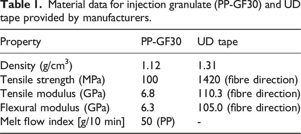
The active-table-based 2D tape placement machine, provided by Conbility GmbH (Herzogenrath, Germany), was employed for manufacturing the inlays through the tape laying process (Figure 1). By utilising a laser with a power of up to 4 kW, in situ consolidation of the tapes can be achieved over high laying speed, facilitated by a compression roller. The placement table was heated during tape laying to counteract warpage, and the tape temperature was monitored using two high-speed pyrometers, to oversee both the tape laying process and subsequent tape consolidation. Various laying speeds and laser power settings were investigated, as detailed in Table 2. Setup of the tape laying machine by Conbility GmbH, Herzogenrath, Germany. Parameters for tape laying.
The placed inlays were preformed before injection moulding by being heated to 200°C using hot air for 12 s. Subsequently, they were transferred in to dies for forming. A pneumatic cylinder (Festo Vertrieb GmbH & Co. KG, Germany) was utilised to ensure a robust process. Upon transferring the inlay to the dies, the lower die was moved upwards at a constant speed of 15 mm/s until reaching the set forming force. The inlays were then shaped under a constant pressure and allowed to cool for 10 s before being removed from the dies. A schematic illustration about the forming process is presented in Figure 2. Schematic illustration of the UD tapes forming process, heating (a), force build-up (b), forming and cooling (c), and physical equipment setup (d).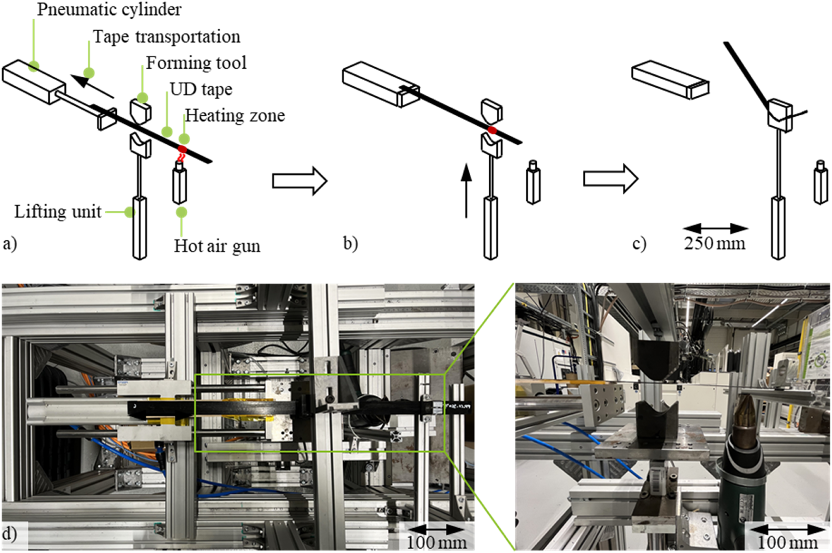
Overmoulding inlay
The production of injection-moulded parts was conducted on an ENGEL DUO 1700, as illustrated in Figure 3. This injection moulding machine is characterised by a maximum clamping force of 17.000 kN, features a swivelling plate function, and incorporates two injection units. The maximum injection volume accounts for 6100 ccm for a screw diameter of 120 mm and 2600 ccm for a screw diameter of 90 mm. The machine is equipped with a trunk-like plunge edge mould. To manufacture the hybrid injection-moulded parts, preformed inlays made of UD tape were manually inserted in the mould and secured in position using vacuum. ENGEL DUO 1700 injection machine with equipped trunk-like mould.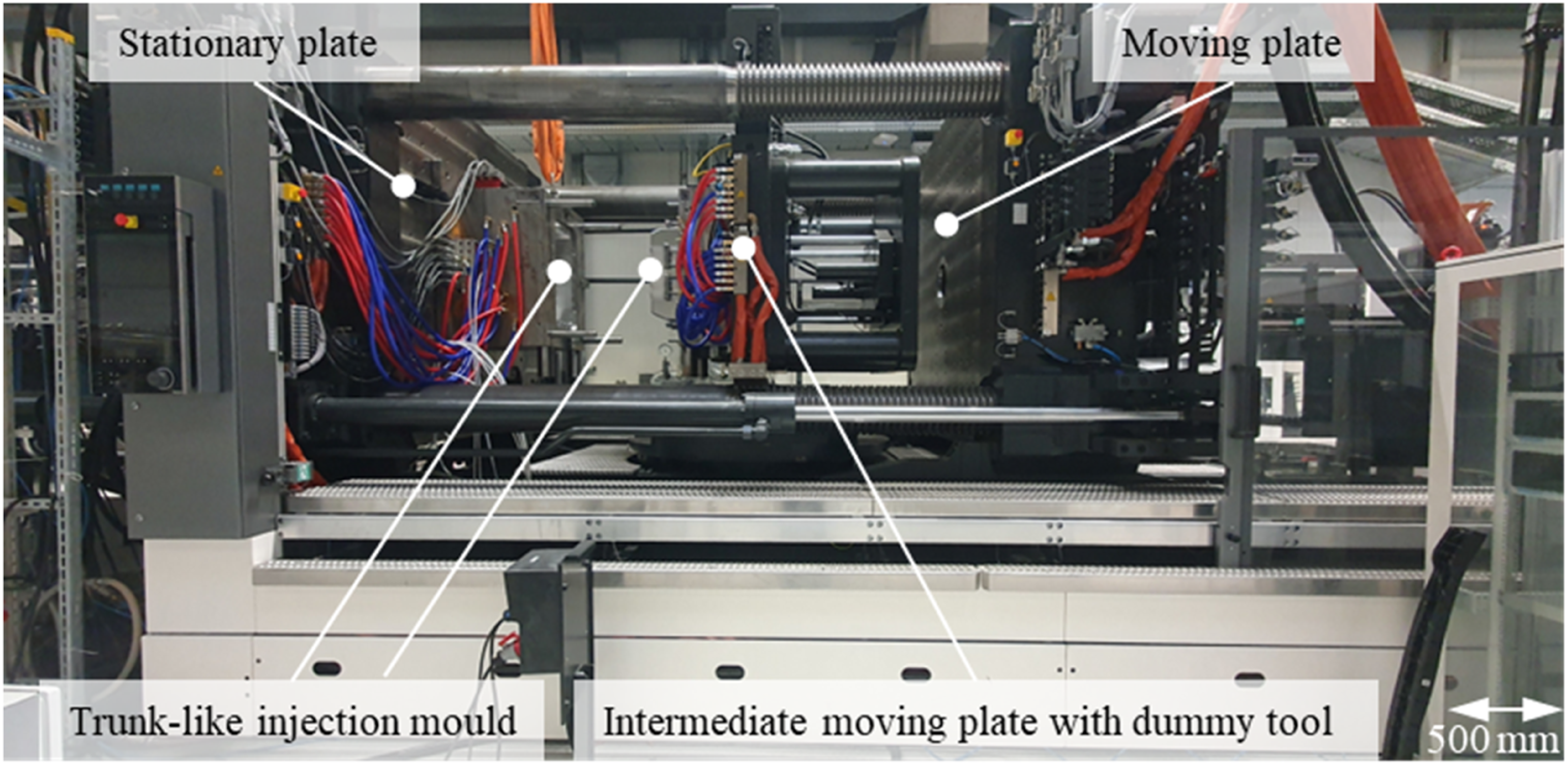
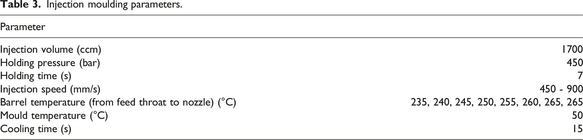
The inlay inserters in the injection mould and the resulting hybrid injection-moulded component are illustrated in Figure 4. Injection moulding parameters, including injection volume, holding pressure, injection speed, and injection temperature, are detailed in Table 3. A cascade control system was utilised for the injection process. Initially, the injection gate positioned at the centre of the mould was opened. Subsequently, the outer injection gates were activated once the melt had flowed over, ensuring comprehensive tool filling. Following the injection moulding process, samples were cut out for further mechanical and optical investigations. Detailed view of the trunk-like mould with inlays made of UD tape and the overmoulded part. Injection moulding parameters.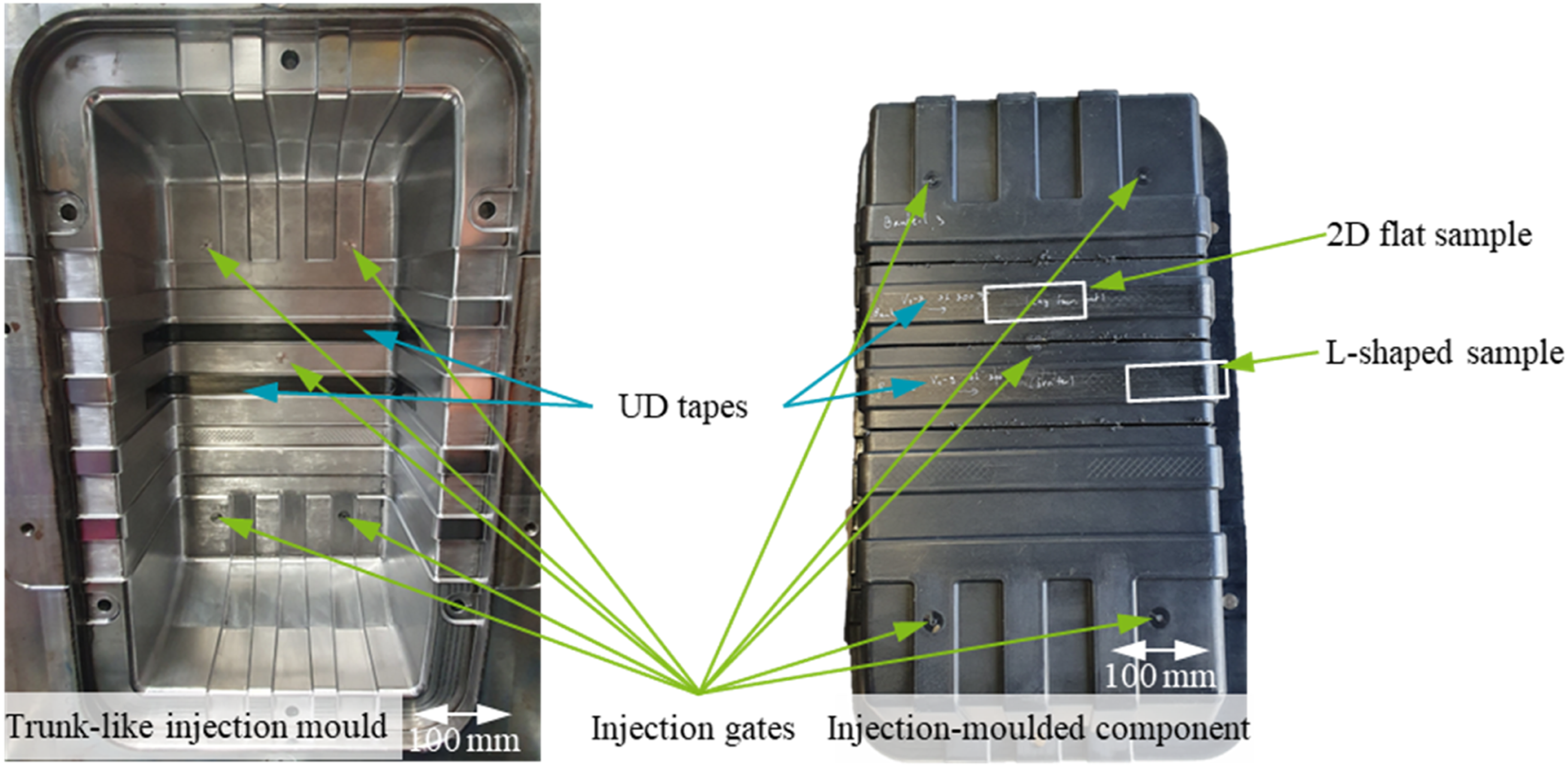
Mechanical test
4-P flexural test
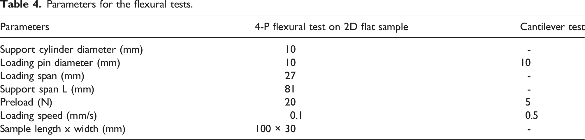
Parameters for the flexural tests.
Cantilever test
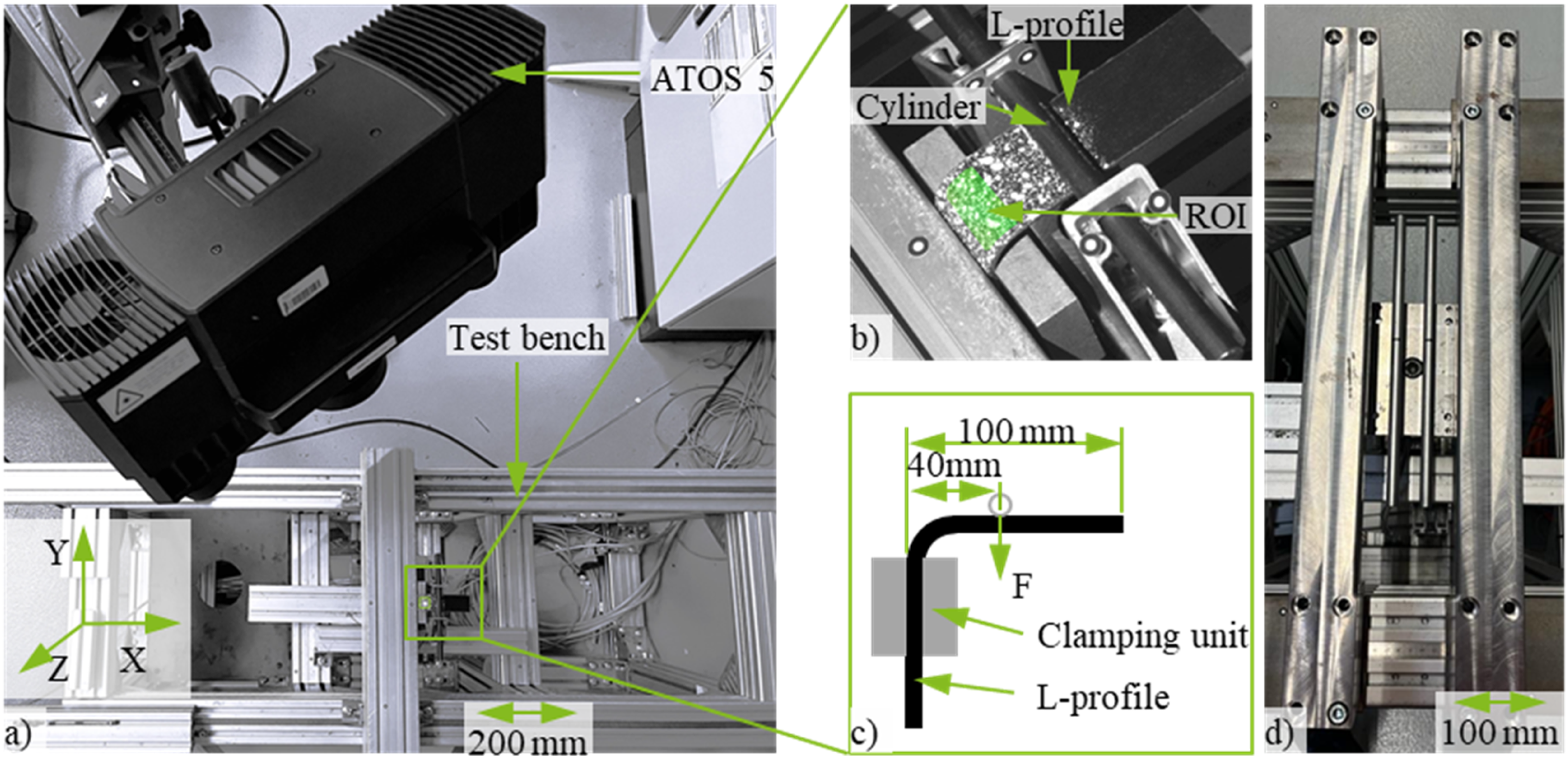
The cantilever test was employed to characterise the L-shaped samples, with particular emphasis on the corner areas, as marked in Figure 4. A loading lever of 40 mm was pre-defined to ensure failure in the corner region. The test setup is schematically illustrated in Figure 5 and includes a test bench for providing loading force and an optical measurement system ATOS 5 for capturing surface displacement and strain. The test parameters are detailed in Table 4, and the samples were loaded up to a target deformation of 30 mm. To evaluate the flexural stiffness, a region of interest (ROI) sized 12 × 25 mm was generated, and the strain was calculated using the software Aramis Professional (Carl Zeiss GOM Metrology GmbH, Germany). The flexural stiffness ( Illustration of the test cell (a), zoomed-in view of the cantilever test on the L-shaped sample (b), a schematically detailed illustration of the cantilever test (c), and the setup for the 4-P flexural test.
Microscopy analysis
The objective of microscopic imaging is to investigate the impact of different laying speeds on the consolidation quality of tapes, the presence of air void inclusions, fibre bundle structure and undulations. Furthermore, it seeks to understand the influence of forming and overmoulding processes on these tape properties. Microscopy images were generated for sample extraction following the tape laying, preforming, and overmoulding processes using a Primotech (Carl Zeiss Microscopy GmbH, Germany). In the case of both formed and overmoulded samples, images were captured 10 mm before the forming area, at the midpoint of the forming, and 10 mm after the forming area. An overview of the sample extraction is depicted in Figure 6. Overview of sample extraction for microscopy.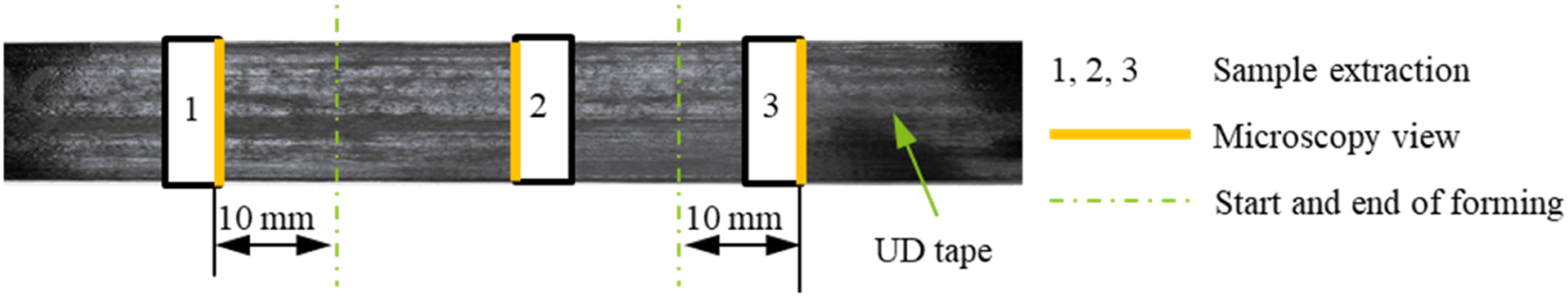
Results and discussion
Investigating the effects of tape laying speed, forming and overmoulding on the inlay’s morphology
Morphology of placed 2D inlay
The morphology of placed inlays was assessed prior to forming and overmoulding, as illustrated in Figure 7. Images were captured from extraction points 1, 2, and 3 of the inlays at a laying speed of 300 mm/s, 650 mm/s, 950 mm/s, and 950 mm/s with lower laser power. Microscopies of the inlays produced with different laying speeds (300 mm/s: a-1, a-2, and a-3, 650 mm/s: b-1, b-2, and b-3, 950 mm/s: c-1, c-2, and c-3) and lower laser power (d-1, d-2, and d-3).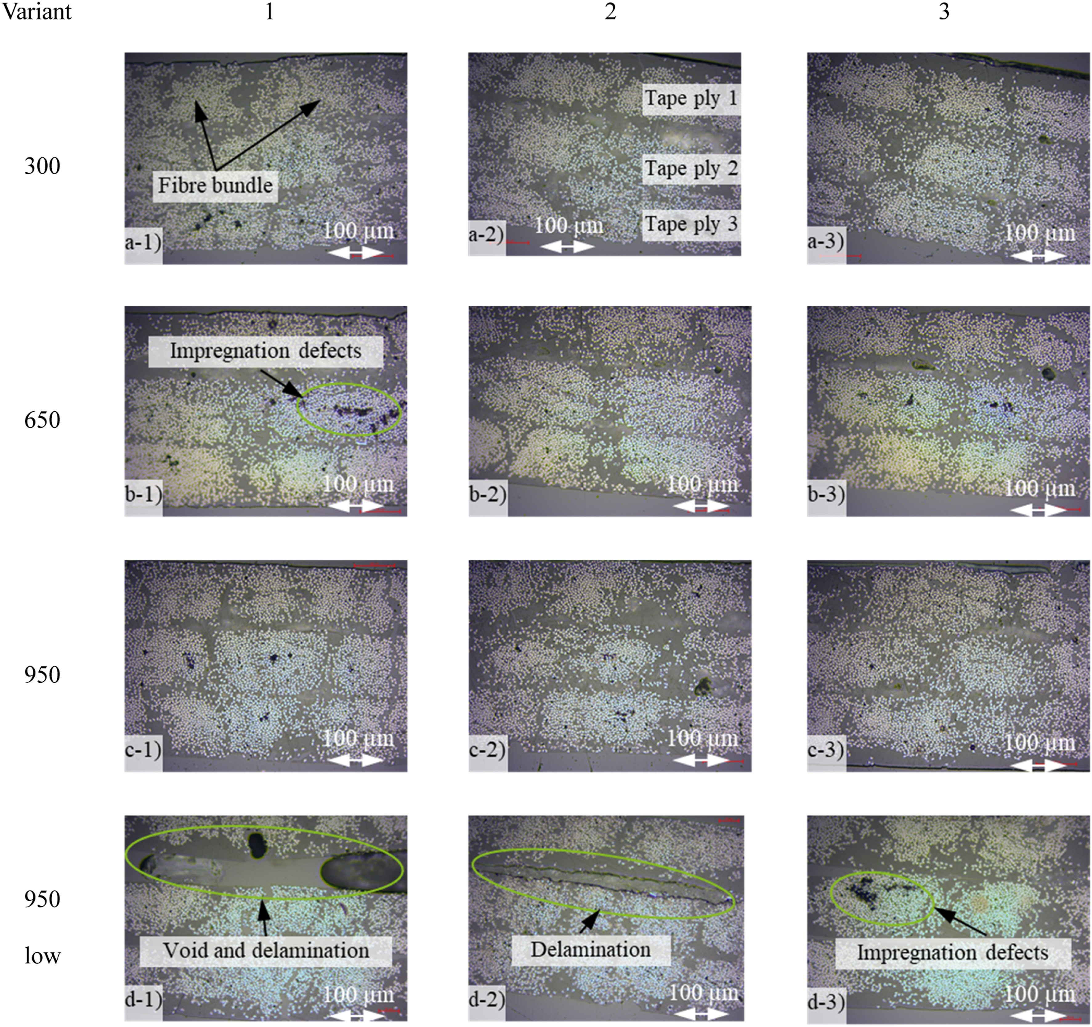
As depicted in Figure 7, the inlays with varying laying speeds of 300 mm/s, 650 mm/s, and 950 mm/s exhibit a homogeneous distribution of fibres. Individual fibre bundles, described in a-1, are discernible between and within the three tape plies (as described in a-2), and no delamination between the tape plies is evident. Void inclusions between the individual tape plies are not observed. Some void inclusions within fibre bundles are noticeable, appearing as black spots (b-1, d-1, and d-3) and attributed to incomplete impregnation in the tape manufacturing process. 30 In addition, the tapes exhibit a very straight profile without any waviness.
In general, no significant differences in waviness, consolidation, or void inclusions are observed between the inlays at different laying speeds, except for the inlay produced at 950 mm/s with lower laser power. However, a notable contrast is evident in the inlay with a lower laser power, where significant void inclusions and delamination are present between the individual tape plies, as shown in Figure 7 (d-1 and d-2). This indicates a lack of consolidation. Additionally, the boundaries between the tape plies are visible (d-2).
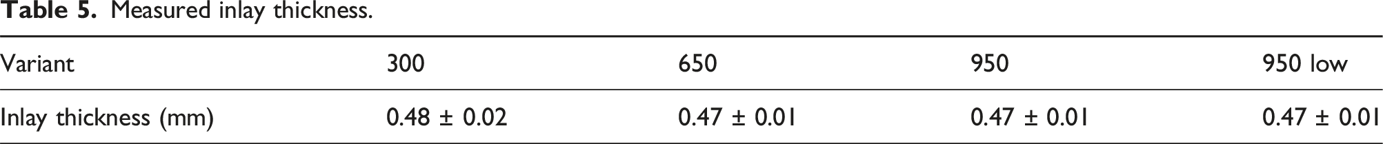
Measured inlay thickness.
Morphology of preformed 3D inlay
For the examination of a 3D preformed UD tape, the locations shown in Figure 8 are utilised for sample extraction. Sample extraction of formed UD tape for microscopy.
The inlay morphology resulting from the forming process is illustrated in Figure 9, featuring panoramic images to offer a comprehensive overview with the entire extent of the fibres. It is worth to note that the tape surface undergoes partial roughening and waviness, as shown in Figure 9 (a-2, b-2, c-2, and d-2), due to the heating and cooling procedures, leading to stress concentration during the sampling and cutting process. This, in return, results in matrix fractures though the thickness direction of the samples, which is however not the primary focus of this research. Microscopic images of the formed inlays produced with different laying speeds: 300 mm/s (a-1, a-2, and a-3), 650 mm/s (b-1, b-2, and b-3), 950 mm/s (c-1, c-2, and c-3), and at lower laser power 950 mm/s low (d-1, d-2, and d-3).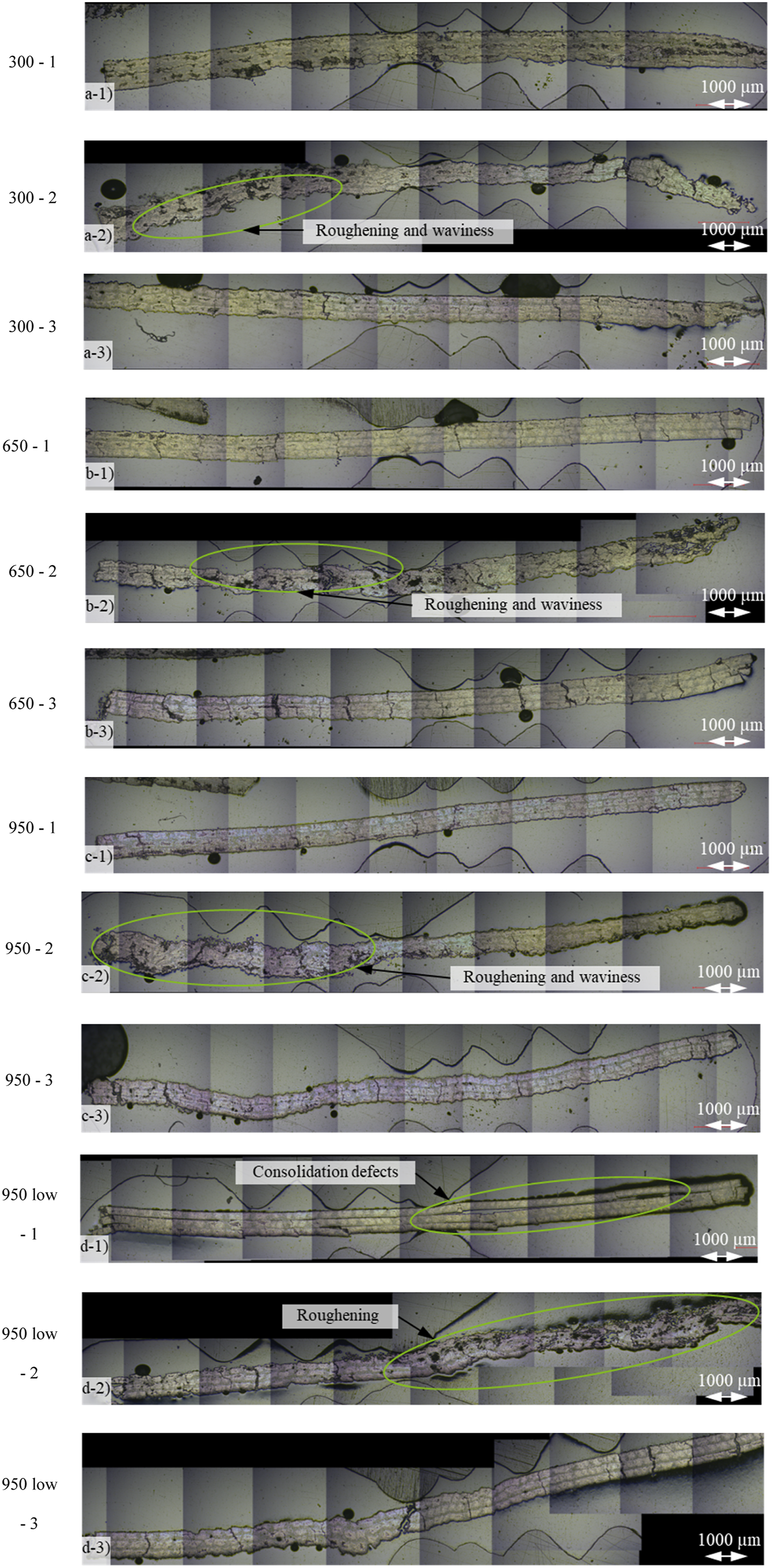
It can be observed that the molten areas ahead of the forming area, especially illustrated in Figure 9 (a-1 and c-3), already exhibit increasing undulations. Particularly in the peripheral areas, as observed in 950 - 3, the tape no longer follows a straight path across the cross-section. The regions within the forming area exhibit increased void inclusions and undulations (seen in a-2, b-2, c-2, and d-2). In the peripheral regions, the UD tape thickens, and the fibre bundles lose their previous structure, rendering individual fibre bundles indiscernible as seen in the roughened areas of c-2 and d-2. The different tape plies blend into each other and cannot be distinguished. In the heated areas, increased air inclusions occur, not between individual tape plies, but within the entire tape.
Delaminated areas are visible in the 950 low sample d-1 with lower laser power, with boundaries between the tape plies. However, in the forming areas observed in d-2, which have been remelted through the forming process, no delamination is observable. The repeated melting and forming process appears to have fused the tape plies together. It is noteworthy that the melting and forming process introduces undulations and void inclusions in the tape. Furthermore, delaminated areas such as d-1 can be rewelded in a cohesive manner.
Effect of overmoulding on the morphology of preformed inlays
Microscopic images of the formed and overmoulded inlays are presented in Figure 10. The contact surface between the inlay and the mould forms a straight and smooth surface, contrasting with the overmoulded inlay side (as illustrated in Figure 10 300-1), thereby smoothing out external undulations. The overmoulded inlay side still exhibits waviness, although less pronounced than those in the preformed inlays before overmoulding. The void inclusions generated by preforming between the individual tape plies are partially minimised by the overmoulding process. Particularly for inlays placed with lower laser power, there is a reduction in delamination between the tape plies, with fewer to no air inclusions discernible. Furthermore, compared to exclusively preformed tape inlays, undulation is reduced. Microscopic images of the formed and overmoulded inlays produced with different laying speeds (300 mm/s, 650 mm/s, and 950 mm/s) and lower laser power.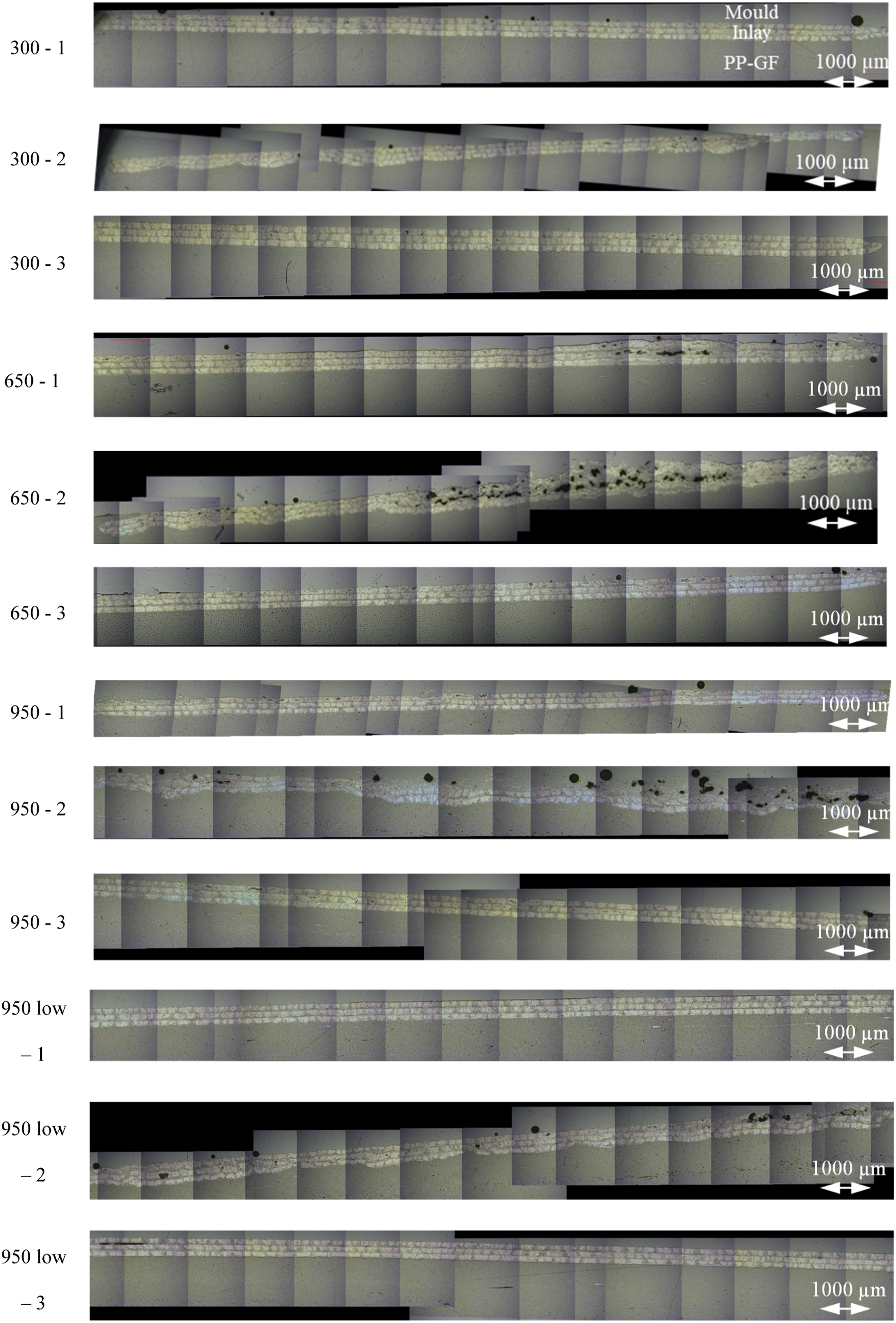
A significant improvement in the forming area is particularly evident when compared to the preformed inlays before overmoulding. Void inclusions are only sporadically present. However, especially variant “950 low” with reduced laser power displays nearly identical quality to the variants with complete consolidation. Void inclusions between the tape plies are no longer discernible and the boundaries between the tape plies are easily noticeable. Overall, it can be asserted that the tape laying speed has no significant influence on the formation of undulations and the distribution of fibre bundles. Void inclusions are primarily driven by the impregnation process during tape production. Instead, the forming process has a substantial impact on the emergence of undulations and the formation of void inclusions. Moreover, this process can be utilised to remedy inadequate consolidation. Additionally, the overmoulding process has proven to be an effective means of smoothing undulations and reducing the number of void inclusions, mitigating the consolidation defects.
Analysis of fibre waviness in the thermoformed region
The heating states of continuous fibres before and during forming are schematically illustrated in Figure 11. Local heating causes spatial melting of the UD tapes, with the surrounding areas remaining in a solid state, serving as fixation points for the continuous fibres, as depicted in Figure 11(a). Continuous fibres in the melting zone become easily deformable due to the loss of matrix support. During forming, the fibres in the upper zone undergo stretching (as shown in Figure 11(b)), leading to matrix squeezing and migrating.
31
Owing to the low matrix viscosity, stressed fibres tend to move inward to toward the neutral axis. Consequently, the surface in the tension zone exhibits relative roughness, as observed in the experimental results shown in Figure 12(a), (c), (e), and (g). Schematic illustration of the morphology of fibres in the heating zone of UD tapes, before forming (a), and after forming (b, c), and physical samples before forming (d), after forming (e, f) (solid black lines indicate continuous fibres). Representative formed UD tapes in the outside and inside view.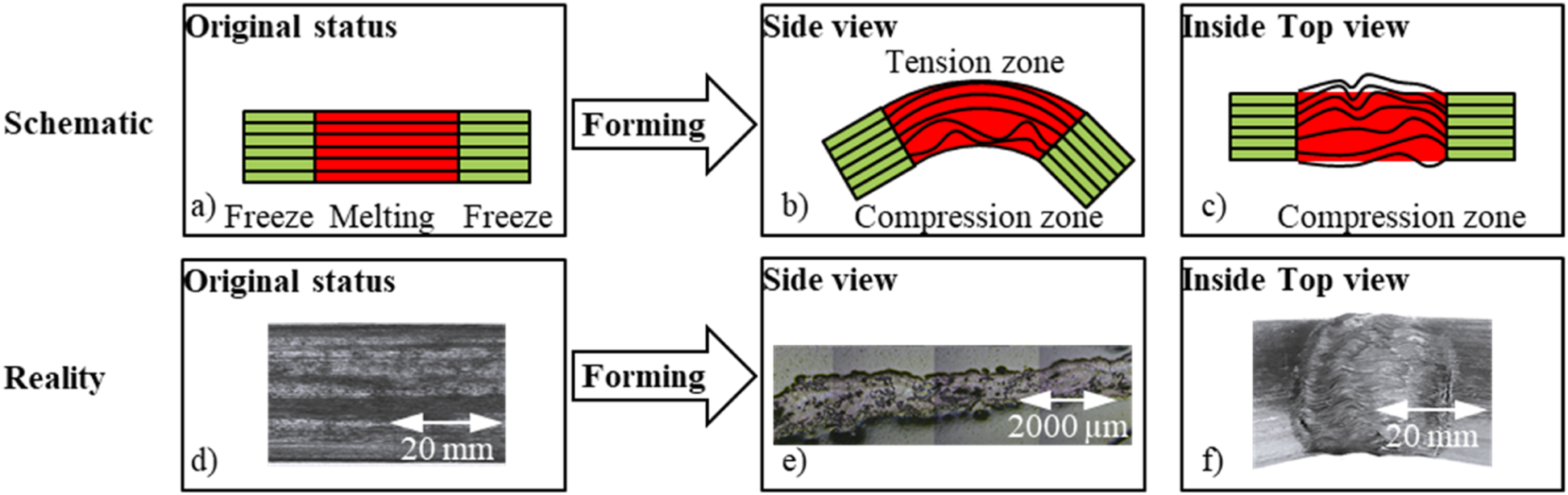
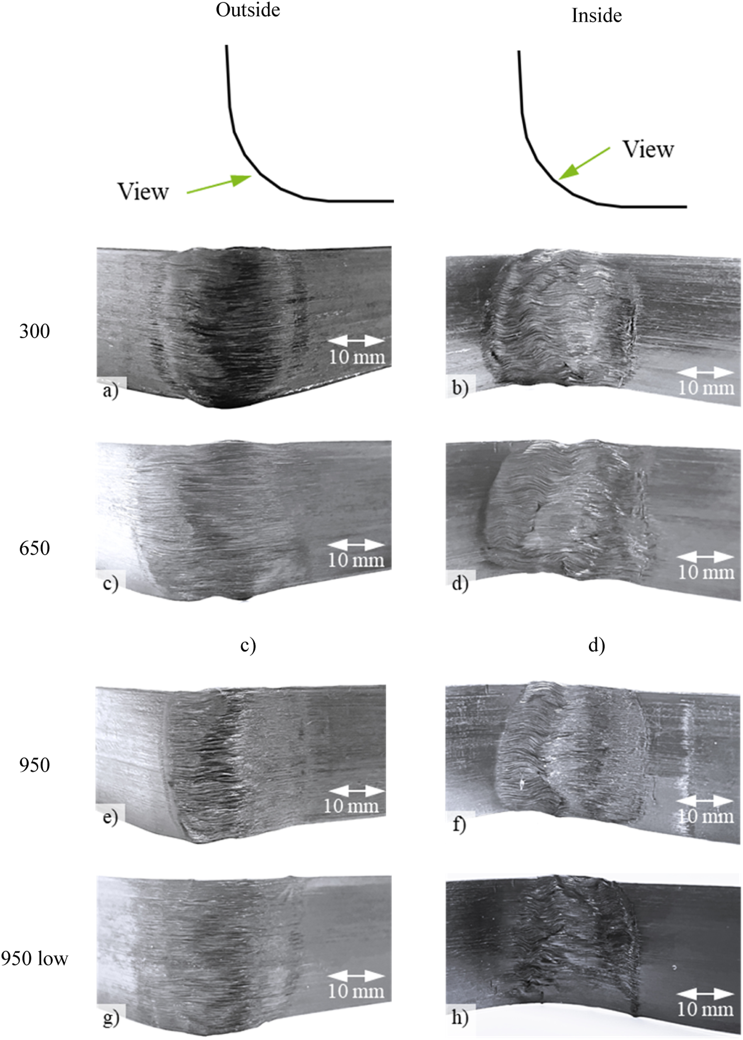
In the lower zone, fibres are compressed, leading to fibre waviness and wrinkling due to limited matrix support at high temperature with low viscosity, 32 as illustrated in Figure 11(b) and experimentally observed in Figure 12(b), (d), (f), and (h). Additionally, fibres in the lower zone can experience transverse flow caused by shearing between the UD tapes and forming mould. 28 This transverse flow induces stretching and fibre waviness in a perpendicular direction of the UD tape due to low stiffness, as shown in Figure 11(c). The resulting fibre waviness causes fibres to be reoriented with changed angles. Due to forming, fibres at the corners take on a 3D geometry, making it challenging to analyse the fibre orientation tensor, compared to fibres in a 2D geometry.
Investigating the influence on mechanical properties
Characterisation on 2D flat sample using 4-P flexural test
The influence of tape laying speed and the corresponding consolidation quality was initially analysed on 2D samples using the 4-P flexural test. The force-displacement behaviour and the determined maximum force and flexural stiffness are summarised in Figures 13 and 14, respectively. It is evident that the flexural stiffness and the max. force are significantly enhanced by the tape compared to samples made of pure PP-GF, increasing from 17.7 N/mm to 57.8 N/mm, and from 129 N to 431 N, respectively. This represents an increase in flexural stiffness between 214 % and 227 %, while the enhancement in the max. force falls within the range of 178 % and 234 %. The enhancement attributes to the dominant high modulus and strength of tape compared to PP-GF. Notably, the laying speed does not significantly influence the flexural stiffness and the max. force of samples with tape. Furthermore, the samples with pure PP-GF, at speeds of 300 mm/s, 650 mm/s, and 950 mm/s demonstrate a gradually decreased flexural stiffness up to the max. force. Experimentally determined force-displacement diagrams of the 2D flat samples (pure PP-GF (a), 300 mm/s (b), 650 mm/s (c), 950 mm/s (d), 950 mm/s low (e)) under the 4-P flexural test. Flexural modulus and strength of 2D flat sample under the 4-P flexural test.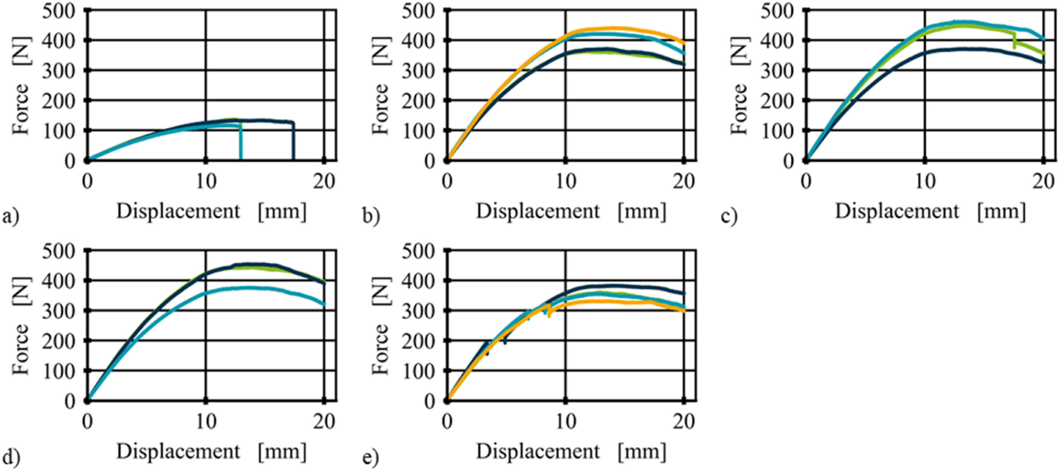
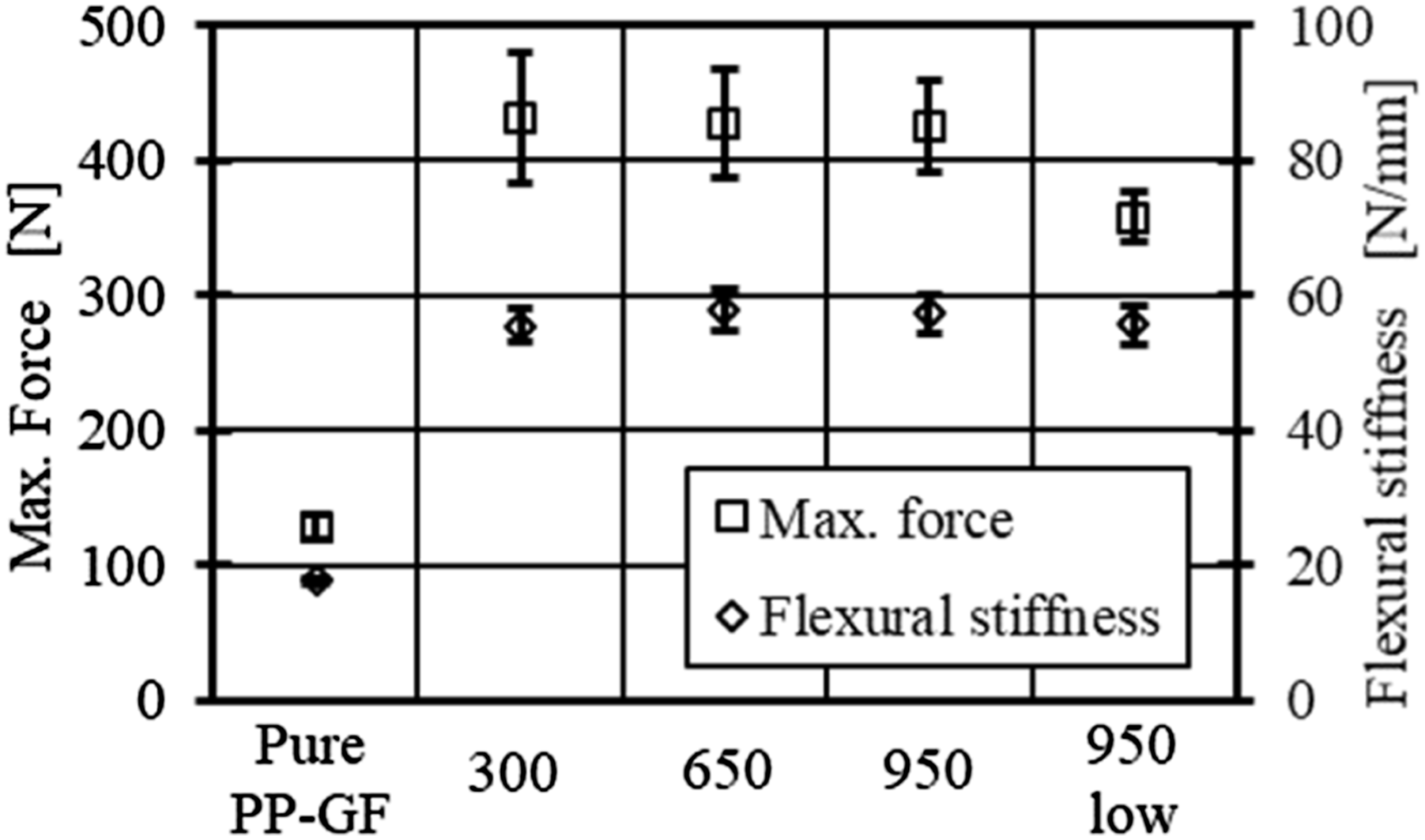
For samples with a constant laying speed of 950 mm/s, those with lower laser power exhibit a similar flexural stiffness, as the stiffness is primarily determined by the UD tape. However, a smaller max. force is demonstrated, which can be caused by the worse consolidation quality and wrapped air voids, as discussed in chapter 3.1.1. As shown in Figure 13(e), under certain deformation, the loading force decreases and increases again with a snap-back response. This behaviour can be caused by locally successive delamination.
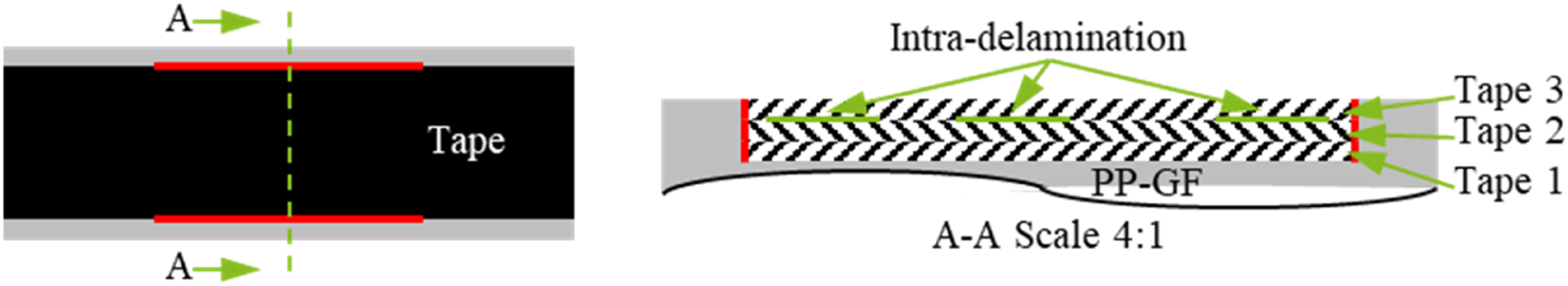
The characterised samples after 4-P flexural test undergo further post-mortem analysis, and the representative failure phenomena are illustrated in Figure 15. Various failure modes among the samples are evident. In comparison to pure PP-GF samples, those with speeds of 300 mm/s, 650 mm/s, and 950 mm/s exhibit filament breakage and peeling off at the interface between the tape and PP-GF. As schematically illustrated in Figure 16, the tapes are embedded into PP-GF during overmoulding. Therefore, high shear stress at the side interface between the tape and PP-GF is induced, as depicted in red in Figure 16. The shear stress is caused by the different modulus and resulting elongation rate of the tape and PP-GF under the 4-P bending test. Furthermore, samples with a laying speed of 950 mm/s and lower laser power demonstrate significant intra-delamination between tape plies. Post-mortem analysis reveals that the intra-delamination occurs between tape 2 and 3, as illustrated in green in Figure 16. There is no noticeable intra-delamination between tape 1 and 2, which can be resulted by optimised interface adhesion quality influenced by the melt temperature during overmoulding. Macroscopic post-mortem analysis of the tested samples under the 4-P flexural test, pure PP-GF (a), 300 mm/s (b), 650 mm/s (c), 950 mm/s (d), 950 mm/s low (e), respectively. Schematic illustration of the interface between tape and PP-GF, and between tapes.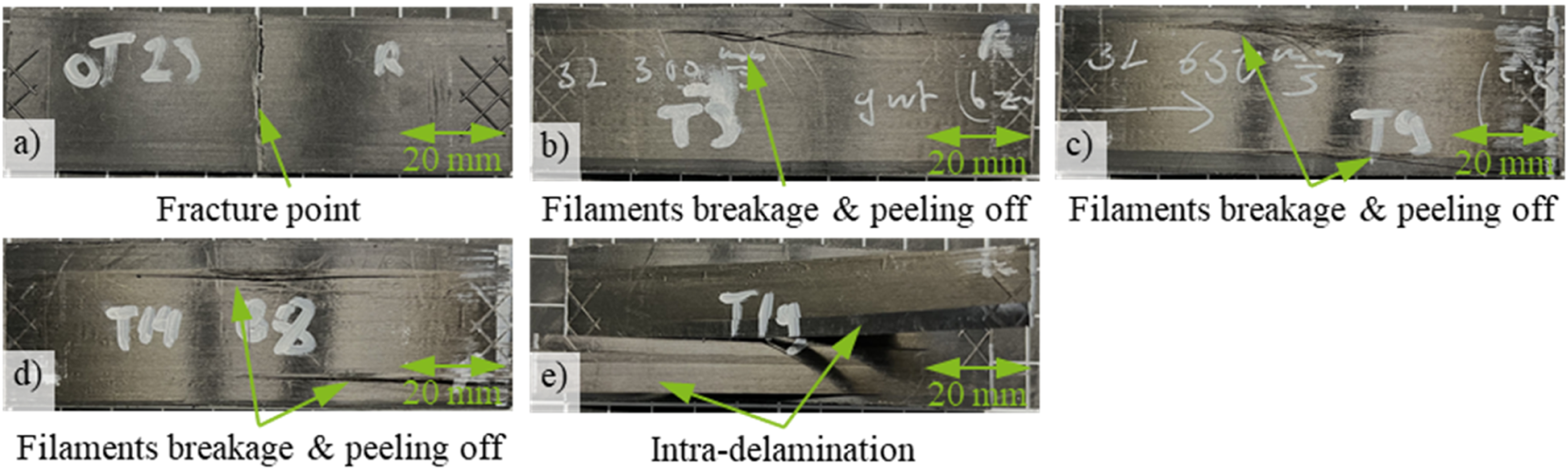
Characterisation on L-shaped samples using cantilever test
The force-deformation curves of the L-shaped samples determined using the cantilever test are illustrated in Figure 17. Notably, L-shaped samples with different laying speeds exhibit a similar mechanical behaviour in this load case. It is worth noting that the L-shaped samples with tape do not fully break until reaching the target final deformation. When compared to pure PP-GF, the max. force and flexural stiffness of the L-shaped samples with tape are significantly increased, as shown in Figure 18. The maximum force is enhanced from 72.2 N to 135.0 N, representing an improvement of 87 %. Similarly, the flexural stiffness is enlarged from 6.30 N/mm to 12.30 N/mm, showing an improvement of 95.2 %. However, it is important to note that the reinforcing effect of tapes on the L-shaped samples is less than that observed in the 2D plate under the 4-P flexural test. This difference is attributed to the geometrical influence of the L-shaped samples and the waved carbon fibres induced by forming. Experimentally determined force-displacement diagrams of L-shaped samples (pure PP-GF (a), 300 mm/s (b), 650 mm/s (c), 950 mm/s (d), 950 mm/s low (e)) under the cantilever test. Experimentally determined maximum loading force and flexural stiffness of L-shaped samples under the cantilever test.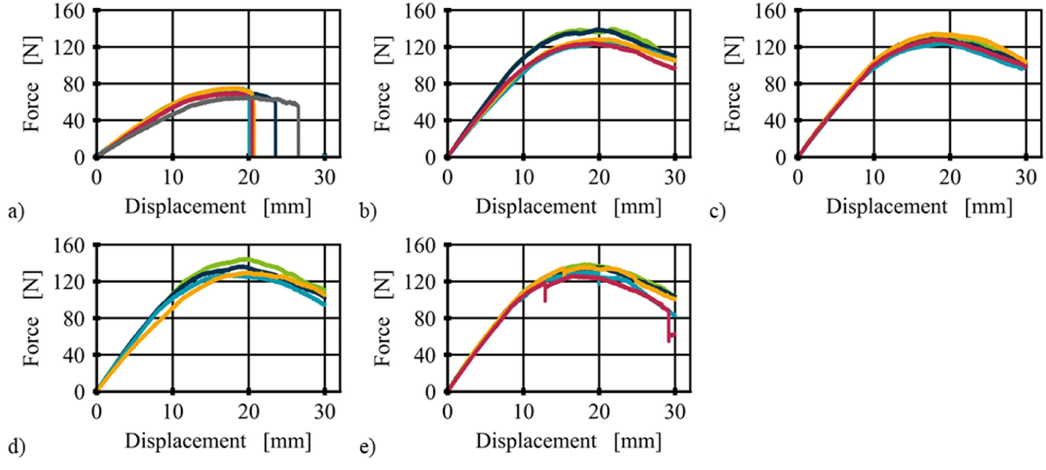
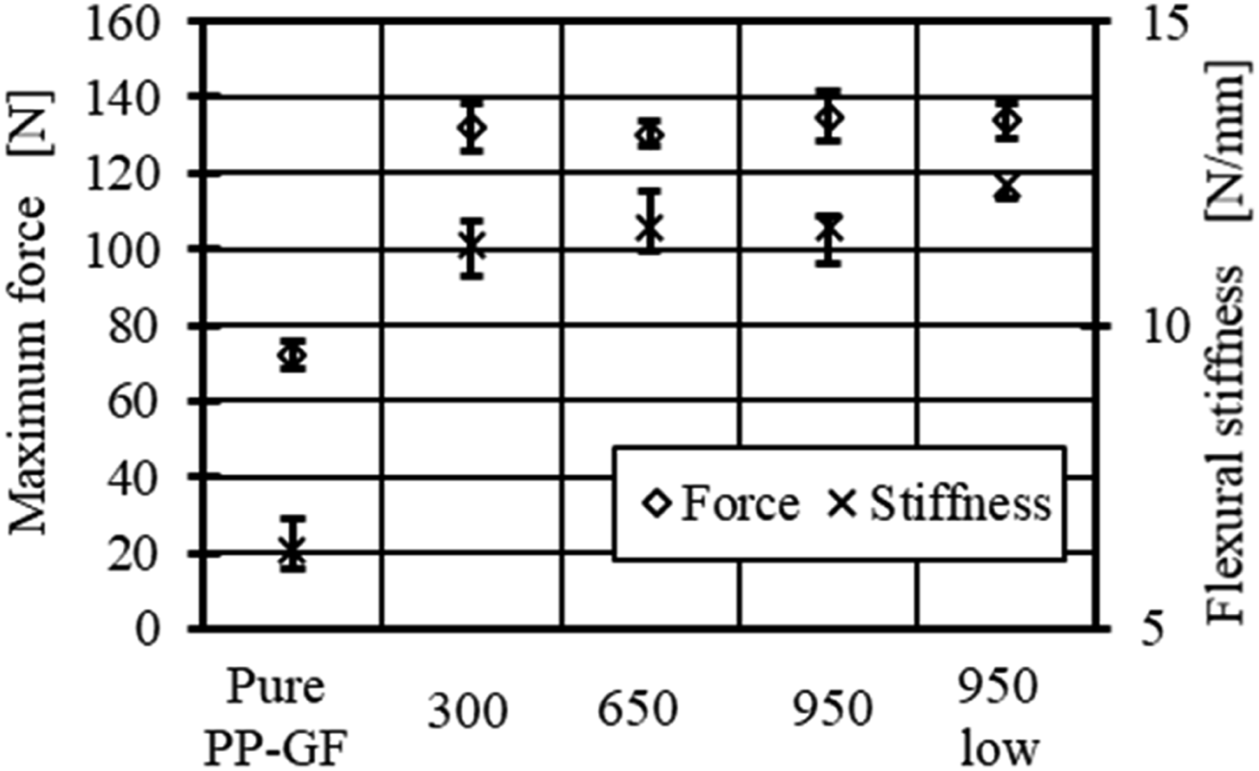
Furthermore, it is observed that the different laying speeds do not result in a significant difference in the maximum force and flexural stiffness. This implies that a laying speed of 950 mm/s can be applied to increase productivity without compromising the investigated quality. Additionally, for samples with a constant laying speed of 950 mm/s and lower laser power, there are force falling steps and quick responses, as shown in Figure 17(e). This behaviour is similar to that under the 4-P flexural test, can be attributed to the local delamination and fibre fractures. However, the maximum force and the flexural stiffness are not worsened by the lower laser power, suggesting that lower laser power could be applied during tape laying to save energy. This depends on the specific objects and loading cases, which should be investigated individually. The effect may also be differenced in impact or cyclic load cases.
The L-shaped samples after the cantilever test undergo post-mortem analysis, and the representative failures are shown in Figure 19. The L-shaped samples made of pure PP-GF experience fractures in the corner area due to high stress concentration under the cantilever test, as illustrated in Figure 19(a). In contrast, L-shaped samples with tapes do not exhibit total failure but rather than localised failures such as carbon fibres breakage, as shown in Figure 19(b)–(e). Furthermore, there is no observable difference between the L-shaped samples with laying speeds of 950 mm/s and 950 mm/s low. This suggests that the tapes at the corners are re-consolidated during forming, and any differences induced during tape laying are eliminated. It can be concluded that tapes are needed to be formed for subsequent processes in specific applications, a lower consolidation quality with lower laser power could be utilised to reduce energy consumption. Macroscopic post-mortem analysis of the L-shaped samples under cantilever test, pure PP-GF (a), 300 mm/s (b), 650 mm/s (c), 950 mm/s (d), 950 mm/s low (e), respectively.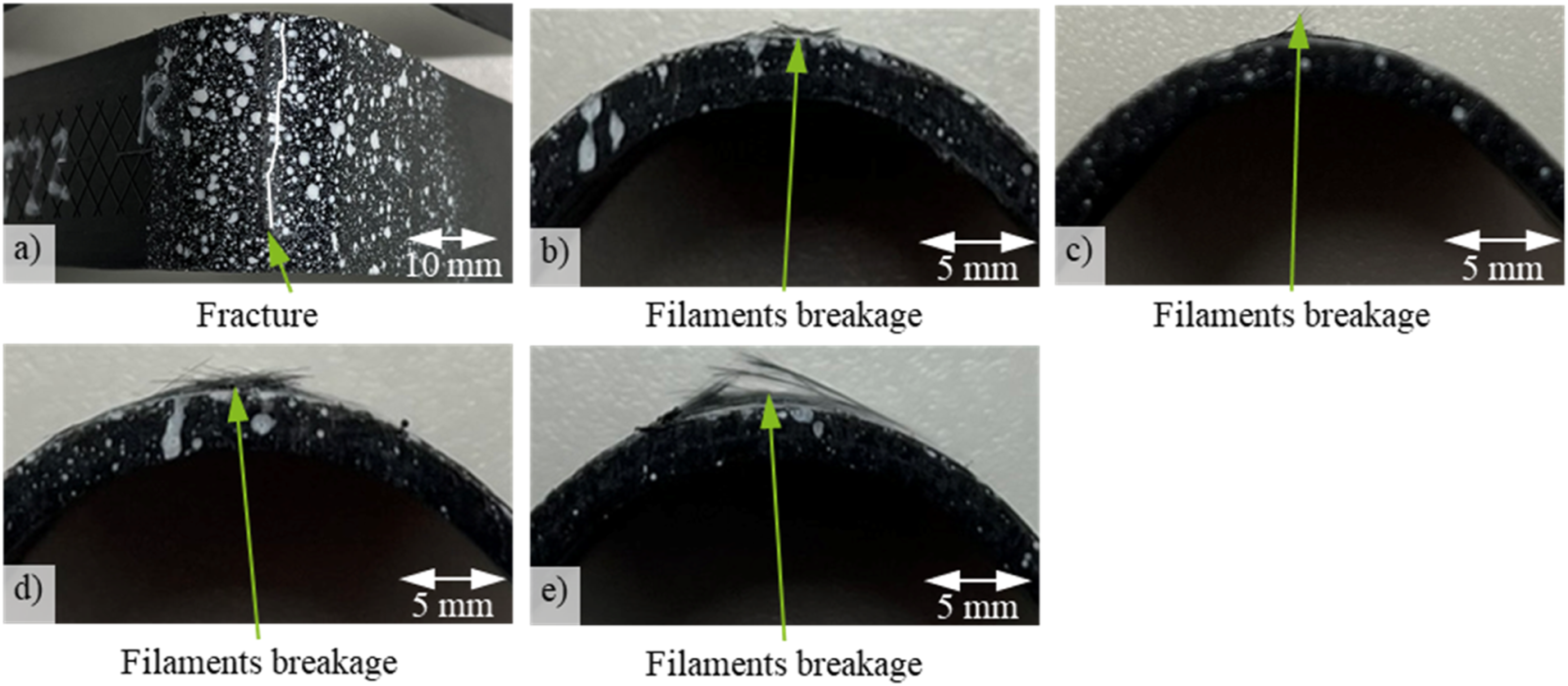
Conclusions
This study investigates the impact of the tape placement process, preforming, and subsequent overmoulding on the quality of UD tape-based inlay was investigated, and taking into account varied laying speeds and applied laser power. Optical microscopy was employed for the morphological analysis of the inlay. The inlay resulted mechanical properties of the hybrid injection-moulded parts were characterised using the 4-P flexural test on extracted 2D flat samples and the cantilever test on extracted L-shaped samples.
It is determined that the inlays with varying laying speeds (300 mm/s, 650 mm/s, and 950 mm/s) exhibit a homogeneous fibre distribution without delamination between the tape plies, when tapes are placed at a sufficiently high laser power. This suggests a high laying speed can be applied for efficient inlay manufacturing. However, inlays manufactured at a speed of 950 mm/s and lower laser power show delamination between tape plies. This delamination is compensated during the inlay forming process, as tapes are remelted and welded together. The forming process introduces fibre undulations and void inclusions in the tape. The subsequent overmoulding process proves effective in reducing fibre undulation, waviness, and minimising void inclusions, attributed to the thermal energy of melt under high pressure. Delamination between tape plies in placed inlay with lower laser power is also reduced. The effects of overmoulding can be limited when the melt temperature closely approaches the material’s melting temperature with a minor temperature difference or under lower pressure. Additionally, these effects can be influenced by the thickness of the inlay.
Moreover, it is observed that laying speeds do not significantly influence the flexural stiffness and maximum force of 2D flat samples under the 4-P flexural test. In contrast, samples with lower laser power exhibit similar flexural stiffness but reduced maximum force due to intra-delamination between tape plies. A similar effect on the increase in flexural stiffness and maximum force is demonstrated in L-shaped samples under the cantilever test, while samples with lower laser power demonstrate a comparable maximum force due to remelting and reconsolidation during the preforming. If tapes and inlay are intended to form for subsequent processes, employing a high laying speed and lower laser power can be a choice for energy conservation.
Footnotes
Acknowledgements
We would like to express our sincere gratitude to the Project Management Agency Jülich (PTJ) for managing the funded project by the Federal Ministry for Economic Affairs and Climate Action (BMWK) under Grant Number 03LB3055. Special thanks to Conbility GmbH for providing the 2D tape placement machine and the optical microscope. Additionally, our thanks go to Mitsui Chemicals Europe GmbH for providing the materials and BBP Kunststoffwerk Marbach Baier GmbH for supplying the injection mould.
Author contributions
H.W. and J.P. conceived and implemented the methodologies, and prepared the original draft and visualisations. K.F. provided project supervision, conceptualisation, conceived the methodologies, reviewed and edited the original draft. M.E. provided project supervision, reviewed and edited the original draft. All authors have read and agreed to the published version of the manuscript.
Declaration of conflicting interests
The author(s) declared no potential conflicts of interest with respect to the research, authorship, and/or publication of this article.
Funding
The author(s) disclosed receipt of the following financial support for the research, authorship, and/or publication of this article: This work was supported by the Federal Ministry for Economic Affairs and Climate Action (BMWK) (03LB3055).