
Abstract
In the present study, a finite element impact model of plain-woven fabric was developed and analyzed using commercial FEM code ANSYS® and then validated via a drop-weight impact experiment. Then numerical analysis was carried out to investigate the low-velocity impact performance of hybrid carbon/Twaron fabric. During the analysis, several factors were considered, such as different hybrid ratios of plain fabric, hybrid fabric with different weaves, and the case of a hybrid multi-layer fabric panel. The results show that among the different types of hybrid plain fabric, the impact scenario of plain fabric with a hybrid ratio of 1:1, where carbon yarns are only in the warp direction and Twaron yarns are only in the weft direction (M4-2), has the best impact resistance performance. The impact scenario M4-2 performed excellently in other weaves, such as twill weave, while impact scenario M4-1 (plain fabric with a hybrid ratio of 1:1, one carbon yarns interval with one Twaron yarn) in basket weave showed high suitability for body armor in terms of impact protection. Additionally, arranging Twaron fabric in the top layers of a hybrid multi-layer carbon/Twaron fabric panel yielded superior impact resistance performance during low-velocity impact events compared to other layer arrangements.
Introduction
Carbon fibers have frequently been used as reinforcement in epoxy resin because of their high specific strength, stiffness in tension and compression, and high flexural properties. Additionally, carbon fiber reinforced polymer (CFRP) 1 composite laminates have been widely used as high-performance materials in aerospace, marine, and automotive industries because of their convenient processing, strong designability in addition to the characteristics described above. 2 However, laminated plates are very vulnerable to external impact due to their layer-to-layer structures. Therefore, several studies have been conducted to improve the impact resistance and damage tolerance of carbon-related materials in practical engineering. 3 This includes fabric structure improvement,4,5 optimal design of ply angle, 6 and hybrid fiber structures.7,8
Hybridization has become one of the most important material design methods in the field of material engineering, 9 which refers to combining two or more different materials to improve the advantages of certain properties and reduce the influence of undesirable characteristics. 10 Para-aramid fibers, such as Twaron fiber (Teijin) and Kevlar fiber (DuPont), have gained significant attention globally as exceptional candidates for specialized high-performance materials in marine, automobile, aerospace, and ballistic applications because of their high tenacity and excellent specific mechanical properties. 11 These fibers are gradually replacing metals in various fields of applications because of their high specific strength, corrosion and impact resistance, and high machinability. Recent research has confirmed that adopting more ductile Twaron or Kevlar fibers can partially replace strong/stiff carbon fiber, effectively increasing toughness and impact resistance to prevent brittle fractures. 12
Recently, materials combined with carbon and aramid fiber have been frequently used to improve energy absorption applications, especially in the aerospace and automotive industries; high-strength and high-toughness carbon/aramid composite has shown great potential for anti-bending aircraft components such as the main wing and fuselage.13,14 Additionally, using carbon/aramid hybrid fabric is very important in manufacturing anti-impact parts in military armored vehicles and bulletproof vests.
Dang et al. 15 evaluated the interlaminar fracture property of three-dimensional (3D) printed continuous fiber reinforced composites with different interlaminar interfaces adopting carbon and aramid fiber. They found that aramid fiber could greatly improve the interlaminar fracture toughness, which can be attributed to the enhanced interlayer bonding and denser bridging fiber. Gao et al. 16 used virtual universal material constitutive code to simulate an efficient hyper-elastic model to reflect the primary mechanical behaviors of carbon-aramid hybrid woven reinforcement. Akmal Zia et al. 17 aimed to print hybrid threads three-dimensionally by merging several types of continuous aramid and carbon fibers. The results showed that the hybrid specimens provided valuable insight into the failure mechanisms, and the positive hybrid effect demonstrated excellent energy absorption capacity. Hashim et al. 9 tested the intraply carbon/aramid fabric/epoxy hybrid composites for static and cyclic loadings at 0°, 45°, and 90° corresponding to carbon, off-axis, and aramid fiber directions, respectively. The tensile test results showed that the carbon direction exhibited the highest strength and modulus, followed by the aramid direction.
In addition, many researchers have conducted related hybridization studies from the perspective of numerical simulation. Rezasefat et al. 18 presents numerical simulation applied to the study of the performance of asymmetric inter-ply hybrids of plain-weave aramid and satin-weave S2-glass fabrics/epoxy laminates subjected to low-velocity impact. The results identified single fiber laminates as the worst designs and hybrid laminates with aramid on the impact side as the best design. Zhou et al. 19 used carbon/basalt (CF/BF) hybridization to improve the impact resistance of CF reinforced epoxy resin (EP) composites, results showed the optimized stacking mode can fully explore the advantage of the rigidity of CF and deformation ability of BF and effectively inhibiting the secondary damage caused by diffusion of fragments. Gloger et al. 20 developed one approach of modifying structure of the ballistic packages for more effective soft body armor, results showed that hybrid packages containing fabrics on the impact side of the projectile and structures embroidered on the back are significantly more efficient than the reverse combination.
Furthermore, the hybridization approach of combining the advantages of carbon and aramid fibers is widely recognized as an effective method and has recently been studied by many other researchers.21,22 However, in the low-velocity impact field, recent research on the hybridization approach primarily focuses on fiber-reinforced composites regardless of experimental study or a simulation study, leaving a noticeable gap in the study of the mechanical performance of pure hybrid fiber/fabric. Study of impact properties of pure fabrics is an important basis for further research on fiber-reinforced composites due to the complexity of component as well as structure in fabric. Therefore, the study of optimizing the mechanical property performance of hybrid fabrics is of great significance to the field of hybrid fiber-reinforced composites.
Additionally, it was indicated that the hybrid parameters, such as fiber types, hybrid ratio, stacking sequence, and hybrid method have significant effects on the mechanical properties of the hybrid fabric. However, understanding the hybrid effects and failure mechanisms of composite materials under different applied loading conditions is complicated and unclear due to the complex and multifarious nature of these hybrid parameters. By isolating the influence of matrix materials such as resins, focusing solely on analyzing the optimized design of the hybrid fabric can reduce the difficulty of solving complex problems and provide an excellent reference value for the design of fiber-reinforced composites.
This study investigates the low-velocity impact performance of hybrid carbon/Twaron fabrics from a numerical perspective. The investigation includes considering various hybrid ratios of carbon yarns in plain fabric, comparing different weaving types, and examining the impact performance of hybrid multi-layer fabric panels. It is important to note that the extensive computational time required for this research reflects the pursuit of a significant breakthrough in the low-velocity field of hybrid fabric.
Methodology
Low-velocity impact model
The 3D woven fabric model was developed at the yarn level using the commercial software SolidWorks®. The yarn-level model accurately captures the behaviors of the fabric during impact events at a mesoscopic scale. 23 In the model, the cross-sectional shape of yarn was assumed to be lenticular, consisting of two symmetrical arcs. The path of the yarn was simulated using an elliptic curve, and the yarn’s cross-section remained constant along its length. The parameters of the yarn in the geometrical model of the woven fabric were obtained from measured data using a digital microscope on Twaron CT fabric provided by TENJIN™ (Japan). Table 1 demonstrates the detailed physical parameters of the fabric. Among the parameters, yarn count, linear and bulk density were obtained from the product manual provided by TENJIN.
Physical parameters of Twaron fabric.

To simulate the low-velocity impact event, the commercial finite element software Ansys® was used in this study. The simulation involved a projectile with a hemispherical head weighing 7.07 kg and having a diameter of 12.7 mm. The remaining parameters and boundary conditions were adopted from practical impact tests. The damage progression during impact was modeled using the general erosion criteria for solid elements when the Lagrange processor was used within ANSYS®. The element erosion was considered as the criterion for determining maximum principal strain failure: that is, when ε ⩾ εf, the element failed and then removed from the calculation, where εf demonstrated the strain at yarn failure set as 2% (Carbon yarn) and 4% (Twaron yarn).
Drop weight impact tester (INSTRON™ Pneumatic Dynatup System 9250 HV) available at Shinshu University was used to conduct the impact experiment to validate the impact model. The plain-woven Twaron® CT made by TENJIN™ (Japan) was employed in this study. This fabric was manufactured using a plain weave of 11 × 11 yarns (per cm2), with each of the yarn consisting of 500 filaments. The bulk and linear density were 1440 kg/m3 and 550 dtex. Other specific and detailed information regarding the model parameters and experimental validation procedures are available in our previous study.24–26 The results confirmed the validity of the low-velocity impact model in accurately simulating practical impact events. Therefore, this study uses the validated model to investigate the impact behavior of hybrid fabrics. Figure 1(a) shows the detailed view of fabric model and Figure 1(b) shows the general view of low-velocity impact model while Figure 1(c) shows image of simulation result during different stages of impact progress.
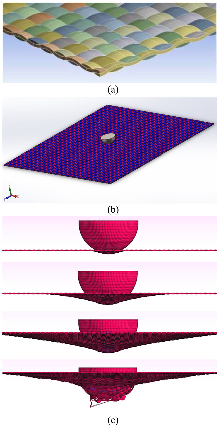
Model used in simulation: (a) detail view of fabric model, (b) general view of low-velocity impact model, and (c) image of simulation result during different stages of impact progress.
Hybrid carbon/Twaron fabric model and impact simulation
To investigate the effect of the hybrid ratio on the impact performance of the fabric, seven plain-woven fabric models with different hybrid ratios of carbon fiber yarn (T700 supplied by TORAY JAPAN) and Twaron fiber yarn (Twaron CT supplied by TENJIN JAPAN) were developed. The parameters of the carbon yarns 27 and Twaron yarns 28 used in the numerical analysis are presented in Table 2. In the fabric model, the yarns were designed to have the same geometric parameters regardless of the yarn type to isolate and evaluate the influence of the hybridization ratio. Additionally, hybrid ratios of carbon fiber yarn and Twaron fiber yarn are denoted by C:A. This ratio means that the fabric is woven repeatedly from C threads of carbon fiber yarns spaced with A threads of Twaron fiber yarns, regardless of whether it is in the warp or weft directions in the fabric. The seven plain-woven fabric models comprised the following: M1, a pure carbon fabric (hybrid ratio of carbon (HR) = 100%); M2, a fabric with a hybridization ratio of 3:1 of carbon/Twaron (HR = 75%); M3, a fabric with a hybridization ratio of 2:1 of carbon/Twaron (HR = 66.7%); M4-1, a spaced type fabric with hybridization ratio of 1:1 (HR = 50%), woven from one thread of carbon fiber yarns interval with one thread of Twaron fiber yarn in both warp and weft direction; M4-2, a vertical type fabric with hybridization ratio of 1:1 (HR = 50%), carbon yarns only in warp and Twaron yarn only in weft direction; M5, a fabric with hybridization ratio of 1:2 of carbon/Twaron (HR = 33.3%); M6, a fabric with hybridization ratio of 1:3 of carbon/Twaron (HR = 25%). Among these models, M2, M3, M4-1, M5, and M6 are interval-hybrid-woven fabrics, while M4-2 is a vertical-hybrid-woven fabric.
Parameters of carbon and Twaron yarn.

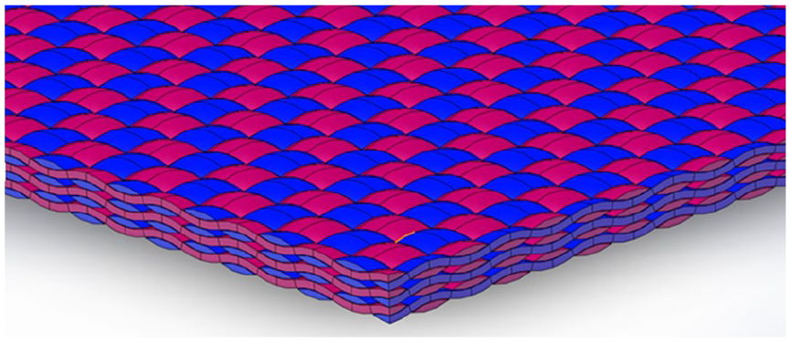
Furthermore, different weaving types of fabric models, including basket and twill, were considered. Figure 2 compares different weaving types of fabric models, where the layers from top to bottom are plain-woven, basket, and twill fabrics, respectively. Additionally, this study considers multi-layer fabric panel scenarios frequently used in human armor applications. Figure 3 shows a model of three layers of plain-woven fabric panels. The same impact boundary condition with the fabric perfectly fixed and a uniform impact velocity of 10 m/s is applied to all impact scenarios. And the numerical simulation results will be compared and discussed in the following section.

Comparison of different weaves.
Multi-layer fabric model.
Result and discussion
Effect of hybridization ratio on low-velocity impact performance of plain-woven fabric
In a typical low-velocity impact event using a drop weight, the projectile impacts the target fabric at a certain velocity. As a result, the yarns are pulled and forced to stretch, generating a resistance force against the projectile. The resistance force gradually increased until it reached its maximum when the yarns reached their strain limit and began to fail. The numerical simulation of the entire impact process was successfully captured in present study, simulated data were obtained and carried out for further comparison and analysis.
Impact resistance force and impact duration time
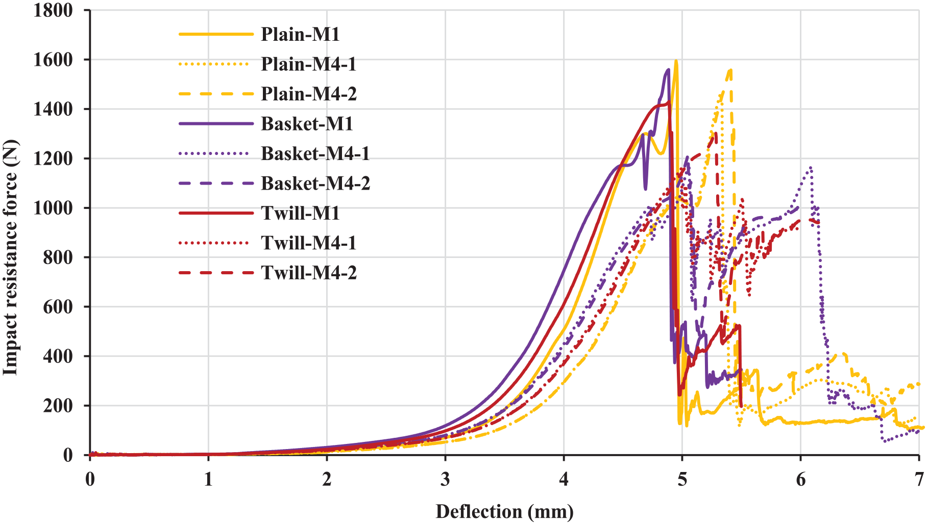
The resistance force to impact is a key indicator of the impact performance of fabric material. It is defined as the reaction force exerted by the fabric on the projectile. The impact duration time is defined as the moment from the beginning of the impact to the time when the maximum resistance is reached. These two indices reflect the impact resistance performance of the fabric. Figure 4 compares the force–time (F–T) histories for the above-mentioned impact scenarios.

Comparison of F–T history of different impact scenarios.
Figure 4 compares the impact performance of the interval-hybrid-woven fabrics group. As the HR decreased, the fabric stiffness decreased, and there was a corresponding decrease in the maximum impact resistance force, while the impact duration time showed an increasing trend. Furthermore, when comparing the two scenarios of a 50% hybrid ratio of M4-1 and M4-2, both fabrics exhibited almost the same stiffness during impact. However, M4-2 demonstrated superior performance in terms of maximum resistance force and duration time. Table 3 shows the detailed data.
Comparison of maximum resistance force and duration time of various impact scenarios.
Maximum deformation and energy absorption
In this study, maximum deformation refers to the distance the projectile travels from the moment it contacts the target fabric to the point of fabric breakage. It is an index to evaluate the material’s ability to resist impact deformation, particularly for body armor applications. Although flexible high-performance fabrics possess exceptional strength, they often rely on large deformation to dissipate the impact energy during events. However, this can lead to non-penetrating injuries more easily. The energy absorption during the impact process is another important index for the evaluation of the impact protection performance of the material. Theoretically, without considering the acoustic and thermal energy loss, energy absorbed by the fabric originates from the kinetic energy loss of the projectile. Therefore, energy absorption by the fabric (E) can be expressed as follows:

where m is the projectile’s mass, and Vi and Vr are the projectile’s initial impact velocity and residual velocity, respectively.
Furthermore, it is highly desirable for material to achieve high energy absorption within the smallest possible deformation range during impacts. As a result, to better evaluate the protective performance of hybrid fabrics, an index

Comparison of impact performance indices of various impact scenarios.

When comparing the impact performance indices of the interval-hybrid-woven fabrics group, it was observed that both the maximum deformation and energy absorption gradually increased as the HR decreased. This is because a reduction in carbon content leads to an increase in Twaron, which has greater impact resistance and can achieve greater failure strain and energy absorption. Additionally, comparing the two scenarios of a 50% hybrid ratio of M4-1 and M4-2, the latter achieves greater values for maximum deformation and energy absorption. Although increasing the hybrid ratio of Twaron will generally make the fabric perform better in energy absorption, fabric type M4-2 exhibits the highest level of comprehensive protection capability among all types, followed by M5, while M2 performs worst. Table 4 shows the detailed comparison data.
Stress distribution
Figure 5 shows the variation in Von-Mises stress distribution contours of the target fabric under different impact scenarios at 0.4 ms, 0.5 ms, and failure moment. The stress gradually spreads from the impact center of the primary yarns (yarns directly in contact with the projectile) toward the secondary yarn (yarns other than primary yarns). The stress exerted on the primary yarns gradually increases and starts to fail after reaching the breaking strength. According to McCrackin et al.,
29
the longitudinal stress wave velocity on a free yarn c depends on both the yarn’s tensile elastic modulus E and the volumetric density


Comparison of stress distribution at different moments in various impact scenarios.
It can be concluded that the stress wave velocity of carbon yarn is faster than Twaron yarn, as supported by the comparative results of stress distribution shown in Figure 5. The higher the HR, the faster the stress propagation in the fabric. This observation is evident from the stress distribution variation in the interval-hybrid-woven fabrics group (M2, M4-1, M6); the fabric with the highest HR yarn exhibits the fastest overall stress dispersion during impact because of its faster stress wave velocity, which leads to shorter impact-resisting times. However, the fabric with the smallest HR in M6 shows the slowest stress dispersion, resulting in longer impact-resisting times. Additionally, the stress distribution of the M4-2 scenario differs from the others due to the asymmetry configuration of the warp and weft yarns. In this scenario, the stress dispersion velocity in carbon yarns (vertical direction) is faster than in Twaron yarns (horizontal direction), and the carbon yarns are more stressed in the failure moment.
Furthermore, it was observed that the fabric is always more stressed, especially at the failure moment during the impact process in M2 and M4-2 scenarios, and least stressed in the M6 scenario. This difference in stress distribution makes the maximum resistance force higher in M2 and M4-2 scenarios and the lowest in the M6 scenario. Generally, the observed stress distribution agrees with the F–T curves of different impact scenarios.
Impact performance of hybrid carbon/Twaron fabric with different weave
The low-velocity impact analysis of hybrid woven fabrics, including plain, basket (2/2), and twill (2/2) weaves, was conducted for comparison. The geometric parameters of various types of fabrics were kept consistent to ensure a fair comparison of the effects of the weave factor. The yarn models in all types of weaves had identical cross-sectional shapes (lenticular) with yarn (thickness: 0.1 mm; width: 0.902 mm; spacing: 0.909 mm). Additionally, the fabrics were identical in terms of thickness (0.2 mm), length (60 mm), and width (60 mm).
Impact resistance force and failure deflection
The results of three typically impact scenarios, namely pure carbon (M1), spaced type with a hybridization ratio of 1:1 (M4-1), and vertical type with a hybridization ratio of 1:1 (M4-2) in different weaves, were extracted for comparison. Figure 6 compares impact resistance force against the projectile’s deflection, which represents the distance the projectile moves during the impact process (with the values of failure deflection equal to the maximum deformation of the fabric) under various impact scenarios with different weaves. It was observed that under the same yarn and material composition conditions, the weaving type influences the stiffness of the fabric exhibited during the impact process. Basket (2/2) weave has the greatest stiffness during the low-velocity impact event, followed by twill (2/2) weave, while plain weave has the least stiffness in all impact scenarios.
Comparison of impact resistance force against deflection.
From the result of impact scenario M1, the plain weave achieves the highest maximum impact resistance force, followed by the basket weave, while the twill weave achieves the lowest. Additionally, the plain weave achieves the greatest failure deflection by a slight difference, whereas there was almost no difference in failure deflection between the other two weaves.
From the result of impact scenario M4-1, the plain weave exhibits a failure mechanism that differs significantly from the other two weaves. It achieves the greatest maximum resistance force, and the yarns in the fabric fracture almost simultaneously, leading to a sharp drop in impact resistance force upon failure. Furthermore, the basket weave and twill weave perform similarly in failure mechanism, where the inconsistency in yarn breakage time within the fabric leads to fluctuations in impact resistance force during the fabric’s failure process. Although there is not much difference in maximum resistance force between these two fabrics, the duration time from the beginning of yarn breakage to the fabric’s complete failure is much longer for basket weave than for twill weave.
From the result of impact scenario M4-2, the plain weave achieves both the highest maximum impact resistance force and highest failure deflection, followed by the twill weave, whereas the basket weave achieves the lowest in both maximum impact resistance force and failure deflection.
Energy absorption and protection performance
Figure 7 compares the energy absorption of different weaves in various impact scenarios. In the impact scenario of pure carbon fabric M1, the plain weave performs best, followed by the basket weave, while the twill weave performs worst in energy absorption. In the impact scenario of hybrid M4-1, the energy absorption performance ranks as follows: basket weave, plain weave, and twill weave. In the impact scenario of hybrid M4-2, twill weave achieves the greatest, followed by basket weave, and plain weave achieves the lowest in energy absorption.

Comparison of energy absorption of different weaves in various impact scenarios.
Additionally, plain weave and twill weave show the same trend in energy absorption across various impact scenarios. Impact scenario M4-2 achieves the highest energy absorption, followed by M4-1, while M1 achieves the lowest. In the basket weave, impact scenario M4-1 achieves the highest energy absorption while M1 achieves the lowest.
To evaluate the comprehensive protection capacity, failure deflection and
Failure deflection and

Generally, impact scenario M4-2 performs excellently in different weaves, especially in plain and twill weaves, whereas impact scenario M4-1 in basket weave shows the most suitable characteristics for body armor in terms of impact protection.
Comparison of stress distribution between different weaves
Figure 8 presents the stress distribution plots of the three different weaves at the moment of failure in impact scenario M4-1, where the three types of fabrics demonstrated completely different stress distribution patterns at the moment of fabric’s fracture. The carbon yarns are more stressed in the failure moment as the stress dispersion velocity in carbon yarns is faster than in Twaron yarns, this is particularly noticeable on basket weave, followed by twill weave, the plain weave showed comparatively uniform in stress distribution with two kind of yarns. While from side view, it can clearly be seen that the failure deflection of plain weave is the largest, while the other two types of fabrics do not differ much, which is consistent with the results given above.

Comparison of stress distribution at failure moment of different weaves in impact scenario M4-1.
Impact performance of hybrid carbon/Twaron multi-layer fabric
Body armor or composites are frequently made of high-performance fabrics assembled into multi-layers to improve their energy absorption capacity. This study focuses on a three-layer plain-woven fabric panel consisting of one layer of Twaron fabric and two layers of carbon fabric. Three scenarios of impact models were designed for the fabric plate: Twaron fabric was placed in the first layer (A1), the second layer (A2), and the third layer (A3) (the layer that comes into contact with the projectile during an impact event is the first layer).
Force–time curve
Figure 9 shows that multi-layer fabric panels exhibit higher maximum impact resistance force compared to single-layer fabric. The variation in elongation at the breakage point of Twaron and carbon yarns resulted in inconsistent impact resistance times for their respective fabrics. This inconsistency led to the fluctuation of impact resistance force during the impact event, resulting in a curve with two peaks, where the first peak is higher than the second. The time corresponding to the first peak signifies the failure moment of the carbon fabric layer, while the second peak time corresponds to the failure moment of the Twaron fabric layer.

Comparison of F–T curve of different impact scenarios.
In the impact scenario of A1, when Twaron fabric was placed on the first layer, both peaks of impact resistance force were the greatest among all scenarios, which reached 4713.2 N. Additionally, the impact resistance time (time at the first peak) was the longest, which reached 5.30 ms. However, there was not much difference between scenarios A2 (3493.5 N, 5.02 ms) and A3 (3330.1 N, 5.03 ms) when Twaron fabric was placed in the second and third layers, respectively.
Comparison of energy absorption and stress distribution
To gain a deeper understanding of the energy absorption mechanism in a hybrid stacked fabric panel, the energy absorption of each layer under various impact scenarios was extracted for analysis, and the protection index
The results presented in Table 6 demonstrate that impact scenario A1 has the best impact resistance performance as it achieved the highest energy absorption and protection index. This was followed by impact scenario A2 which gained a slight advantage over A3. These findings indicate that if Twaron fabric is arranged in the upper layers of a hybrid multi-layer fabric panel, it exhibits better energy absorption capacity. When the Twaron fabric was arranged in the first layer, it achieved an energy absorption of 2.52 J, while it achieved 1.96 and 1.81 J when arranged in the second and third layers, respectively. Additionally, carbon fabric performs best in energy absorption when arranged in the middle of the fabric panel. The average energy absorption of carbon fabric was 1.25, 1.39, and 1.34 J when arranged in the first, second, and third layers, respectively.
Energy absorption of each layer and
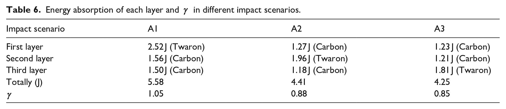
Figure 10 demonstrates comparison of stress distribution at failure moment of Twaron layer in hybrid multi-layer impact scenario A1, A2, and A3, it can be seen that when Twaron fabric is placed in the first layer (A1), the level of overall stress on the fabric at the moment of fabric’s failure is the highest, followed by when it is placed in the second layer (A2), and the overall stress is the lowest when placed in the third layer (A3). The adequate stressed of yarns in fabric reflects the fuller participation of the fabric in resisting the impact, resulting in higher energy absorption. This is consistent with the results obtained.

Comparison of stress distribution at failure moment of Twaron layer in hybrid multi-layer impact scenario.
This result can be explained by the tendency of the fabric to be damaged by shear in the case of high-velocity impact events, while it is prone to be damaged by tensile in the case of low-velocity impact events. Therefore, in low-velocity impact events, arranging the fabric with stronger resistance to tensile fracture (Twaron) in the upper layer facilitates the absorption of the impact energy in the hybrid fabric panel.
Conclusion
In this study, numerical analysis was conducted to investigate the low-velocity impact performance of hybrid carbon/Twaron fabric. The analysis considered several factors, such as the HR in plain weaves, different weaving types, and multi-layer hybrid fabric panels. The following can be concluded:
■ Among the seven different impact scenarios with different hybrid ratios of carbon/Twaron plain woven fabric, the F–T curves showed that the impact scenario M4-2 (the vertical type with a hybridization ratio of 1:1) achieved the greatest maximum impact resistance force, third impact resistance time, and second failure deflection. Additionally, the impact scenario M4-2 exhibited the best performance in energy absorption capacity and protection performance index
■ Three typical impact scenarios were compared: pure carbon (M1), spaced type with a hybridization ratio of 1:1 (M4-1), and vertical type with a hybridization ratio of 1:1 (M4-2). The impact scenarios were evaluated under different hybrid weaving types: plain, basket (2/2), and twill (2/2) weaves. The result showed that the impact scenario M4-2 performed excellently in different weaves, especially in plain and twill weaves, whereas the impact scenario M4-1 in basket weave was most suitable for body armor in terms of impact protection.
■ A three-layer fabric panel consisting of one layer of Twaron fabric and two layers of carbon fabric was focused on in this study. The results indicated that when Twaron fabric was arranged in the upper layers of a hybrid multi-layer fabric panel, it achieved the greatest maximum impact resistance force and longest impact resistance time. Therefore, this arrangement led to the best energy absorption capacity among all panel types.
Footnotes
Declaration of conflicting interests
The author(s) declared no potential conflicts of interest with respect to the research, authorship, and/or publication of this article.
Funding
The author(s) disclosed receipt of the following financial support for the research, authorship, and/or publication of this article: The authors gratefully acknowledge the financial support from the Fujian Provincial Department of Science and Technology, for the Project of Natural Science Foundation of Fujian Province (No. 2022J011111) and the Guiding Project (No. 2022H0048). We also gratefully acknowledge the financial support from Quanzhou Dongnuo Technology Co., Ltd for Project 2021K20.