
Abstract
With the rapid development of modern science and technology, a kind of invisible pollution named electromagnetic radiation has increasingly attracted the attention of all sectors of society. Therefore, electromagnetic shielding protective clothing is widely used by people for daily life and work. More and more scholars and researchers are paying attention to this research direction, and they have done a series of related research on how to improve the electromagnetic shielding effectiveness of clothing materials. At the same time, the related comfort properties of these clothing materials should also be concerned because they will greatly affect the wearer’s experience. This study evaluated the related comfort properties of a kind of copper-plated nonwoven materials with different electromagnetic shielding effectiveness, including air permeability, water vapor permeability, and thermal resistance. The result shows that electromagnetic shielding effectiveness is positively related to the amount of plated copper based on this kind of copper plating method. Other experiment results display that air permeability and water vapor permeability of this kind of material are negatively related to its electromagnetic shielding effectiveness. On the contrary, their thermal resistance is positively related to their electromagnetic shielding effectiveness. In addition to the above, it also found that air permeability and water vapor permeability have a positive correlation with optical porosity, and thermal resistance has a positive correlation with volume porosity.
Keywords
Introduction
In the modern age with the rapid development of science and technology, the pollution of electromagnetic radiation which is called the “invisible killer” has attracted more and more attention from all sectors of society. 1 As more and more electronics and electrical equipment are put into use, electromagnetic waves of various frequencies and different energies are flooding every corner of the earth and even outer space. 2 For the human body, a benign conductor, electromagnetic waves will inevitably constitute a certain degree of harm. In people’s daily life, the radiation sources that may have an impact on human health are mainly mobile phones, computers, TVs, microwave ovens, refrigerators, and other household appliances. During the working terms, radiation sources that may cause harm to the human body include mobile phone signals, network signals, broadcast signals, radar systems, and other signal transmission equipment; railways, airplanes, and other transportation equipment; and some medical equipment that uses microwaves and X-rays. 3 As early as 1972, the United Nations Conference on the Human Environment listed the treatment of electromagnetic radiation pollution as a key environmental protection project and listed it as a public hazard. 4 However, the harm to electromagnetic radiation, especially its impact on human health, has always been a very controversial topic. Most studies so far believe that excessive electromagnetic radiation will cause adverse effects on the human body, for example, it can induce cardio-cerebrovascular blockage, neurological decline, cancer, or affect the central nervous system, sympathetic nerves, and autonomic nerves of the human body. 5 Therefore, the research and development of anti-electromagnetic radiation products have gradually attracted the attention of governments and scientific research institutions around the world. How to prevent and eliminate the impact of electromagnetic wave radiation on human production and life and the harm to human health has become an important concern for all countries in the world today. 6
At the present, the research and development of electromagnetic protective fabrics have become an increasingly important topic. The principle of electromagnetic shielding is mainly to prevent the propagation of electromagnetic energy through the reflection loss and absorption loss of the shielding body. 7 Therefore, electromagnetic shielding materials are divided into reflection loss type, absorption loss type, and a combination of reflection and absorption according to their principles. In terms of preparation, it is mainly divided into structural composite type, surface coating type, and a combination type of the two. 8 In this paper, the electroless plating method is used to prepare the copper coating on the surface of the nonwoven fabric and study the relationship between the electromagnetic shielding effectiveness and comfort performance of this kind of material. Electroless plating uses the principle of oxidation-reduction reaction in chemistry to reduce the ions of the plating layer to the surface of the substrate to be plated with catalytic activity, and deposit and gather a plating layer with a certain binding force. 9 For the surface coating of textile materials, electroless plating is more suitable. Compared with other methods, electroless plating has lower requirements on experimental conditions and does not require too much equipment to participate. It has the advantages of convenience, easy operation, and cost-saving. 10 When the electroless plating process is carried out, the pre-treatment is taken first and then the autocatalytic reaction is used to control the flow and process. Finally, a layer of ideal plating is formed on the surface of the base material. The plating layer formed by the electroless plating process generally has small and uniform metal particles and has good shielding performance. 11 A kind of nonwoven fabric is used as the base material for electroless plating method, mainly to improve the comfort performance of the electromagnetic shielding fabric. 12 Based on the reading of a large amount of literature, it can be found that most researchers focus more on how to improve the effectiveness of electromagnetic shielding materials and there are very few studies on their related comfort performance.13,14 At present, as the market develops more and more used for clothing, the related comfort performance of electromagnetic shielding materials will surely become the focus of research. 15 Therefore, this article will mainly study the correlation between the electromagnetic shielding effectiveness and the related comfort performance of the fabric, including air permeability, water vapor permeability, and heat transfer performance. In addition to this, the influence of various parameters on the related comfort properties and the quality index evaluation will be researched and analyzed.
Material and method
Material
Preparation of copper plated “MILIFE.”
Material: A kind of nonwoven fabric named MILIFE®12 has been used for this paper. It comes in multiple varieties consisting of oriented, continuous polyester filaments having a diameter of about 10 µm. The basic information about “MILIFE” shows in Table 1.
Basic information of the “MILIFE.”

Instrument: Electronic balance, Magnetic stirrer, Constant temperature water bath, Oven, Beaker.
Reagent: Sodium hydroxide (NaOH), Tin (II) chloride (SnCl2), Palladium (II) chloride (PdCl2), Copper sulfate pentahydrate (CuSO4.5H2O), Ethylenediaminetetraacetic acid disodium salt (EDTA.2Na), Potassium sodium tartrate (KNaC4H4O6.4H2O), Potassium ferrocyanide (K4[Fe (CN)6] ·3H2O), 2,2′-Bipyridine (C10H8N2), Formaldehyde (CH2O).
All above chemicals are supplied from company SIGMA-ALDRICH Germany.
Method-electroless copper plating:
Step 1 ‒ Surface treatment: 1.5 g of NaOH was put in a beaker, then diluted to 100 ml with distilled water. The diluted NaOH solution was placed in the constant temperature water bath and heated to 40°C. MILIFE® fabric was added to the solution and heated for 10 min. Then took it out and rinsed it.
Step 2 ‒ Activation: 1 g of SnCl2 was put in a beaker, then diluted to 100 ml with distilled water. Put the processed MILIFE® fabric in the beaker for 10 min and took it out then rinse it.
Step 3 ‒ Activation: 0.05 g of PdCl2 was put in a beaker, then diluted to 100 ml with distilled water. Put the processed MILIFE® fabric in the beaker for 10 min. Then rinsed and dried it when the time was up.
Step 4 ‒ Deposition: 1.3 g of CuSO4.5H2O, 2 g of EDTA.2Na, 2 g of KNaC4H4O6.4H2O, 0.008 g of (K4[Fe (CN)6] ·3H2O, 0.001 g of C10H8N2 and 1.5 ml of CH2O were taken together in a beaker and diluted to 100 ml with distilled water. The solution was placed in the constant temperature water bath and heated to 45°. The processed MILIFE® fabric was added to the solution and heated for 20 min. Then rinsed and dried it when the time was up.
Copper plated “MILIFE.”
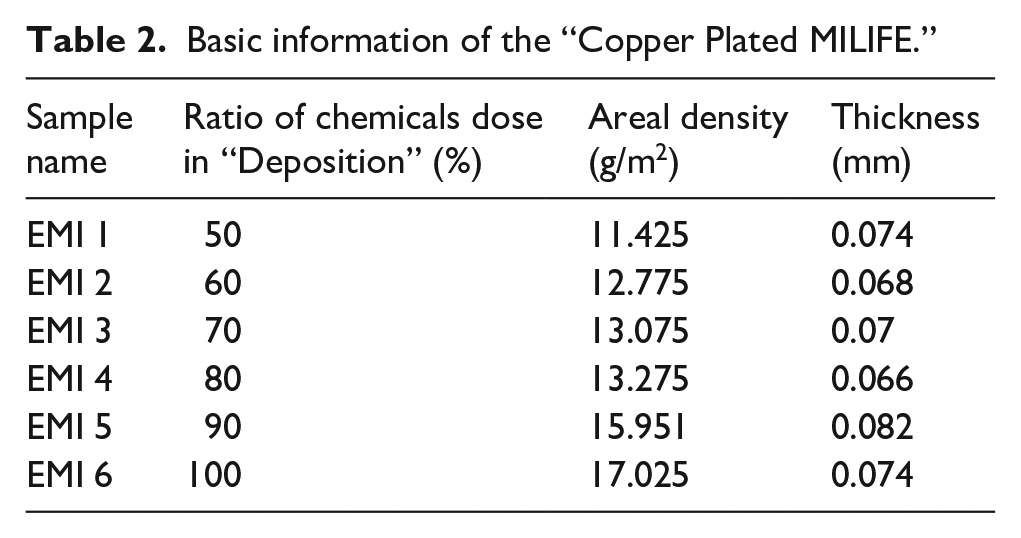
By changing the metering of chemicals in the above experiment’s step 4, the samples with different electromagnetic shielding effectiveness can be obtained. The fourth step in the above experiment is the original dose of the chemicals. For other samples, the ratio of chemicals used in step 4 decreased by 10% successively. In Table 2 shows the detailed information of “Copper Plated MILIFE” samples with different ratios of chemical doses in “Deposition.” Figure 1 shows the SEM of the “Copper Plated MILIFE” samples, it can be observed that the nonwoven structure of MILIFE. And Figure 2(a) presents the appearance changes of the MILIFE after copper plating. In addition to this, the metal elements on the surface of the “Copper Plated MILIFE” sample was also examined. Through the EDX and XRD analysis of the sample EMI6, it can be concluded that other metal elements except copper cannot be detected on the sample surface by this electroless copper plating method.
Basic information of the “Copper Plated MILIFE.”

SEM of the “Copper Plated MILIFE.”
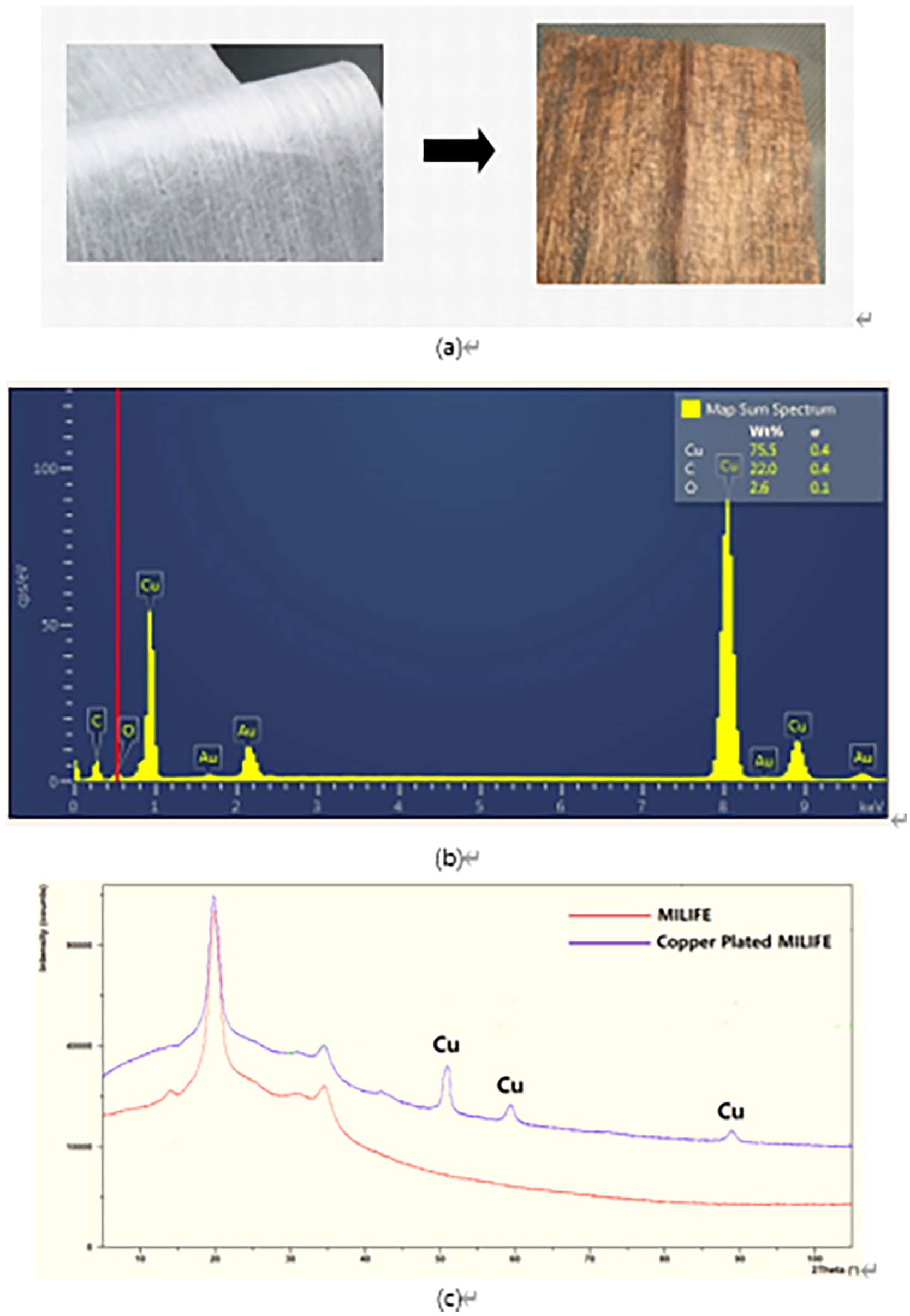
Appearance changes of the “MILIFE” after copper plating (a), EDX (b), and XRD (c) of sample EMI6.
Method
Fabric physical properties and porosity
The fabric thickness was measured according to the EN ISO 5084 standard. 16 The vertical distance between the front and back of the fabric under a certain pressure is the thickness. 17 In this paper, the fabric thickness meter with a presser foot diameter of 50 mm was used to measure, and the pressure applied to the fabric is 1.0 kPa. The area density of the fabric samples was measured following the ISO 3801 standards, including the length, width, and weight of fabric samples. 18 Within the fabric industries, it is called grammage and is expressed in grams per square meter (g/m2) (GSM). 19 In this paper, porosity is divided into optical porosity and volume porosity for measurement and calculation. Regarding the acquisition of the optical porosity of the fabric samples, it is obtained through a microscope under the transmitted light image and processed by the image software (image analysis). 20 Then the parameters including pore number, size, and distribution will be obtained, and further computer calculations will yield the optical porosity of the samples. 21 And the volume porosity 22 can be calculated via volume packing ratio according to the following equation (1):

Where, Vfiber and Vfabric are the volumes of the fiber and fabric; mfiber and mfabric are the mass of the fiber and fabric; ρfiber and ρfabric are the density of the fiber and fabric; GSM is the area density of the fabric and t is the thickness of the fabric. In this paper, ρfiber is the fiber density of “Copper Plated MILIFE” and it can be calculated following the equation (2):

Where, mMILIFE and mCopper Plated MILIFE are the mass of the MILIFE and Copper Plated MILIFE; ρpolyester and ρcopper are the density of the polyester and copper.
Electromagnetic shielding effectiveness
According to the ASTM D4935-10 standard 23 for the planar materials, all fabric samples were tested from 30 MHz to 3 GHz by the plane-wave and far-field EM wave. This kind of measurement standard calculates the electromagnetic shielding effect of the fabric samples by the insertion loss method. 24 The test machine is built up with the sample holders and network analyzer produced by Rohde & Schwarz company. The network analyzer is an important part of the machine and is used to get and receive electromagnetic signals. 25 In this paper, the fabric samples were measured five times at different places, and calculated the average as the result.
Air permeability
There are two indicators of the air permeability of the fabric, 26 one is the volume of air flowing through the unit area of the fabric in unit time under the specified pressure difference between the two sides of the fabric and its unit is l/m2 s. 27 The other refers to the rate at which the airflow passes vertically through the sample under the conditions of the specified sample area, pressure drop, time, and its unit is mm/s. 28 In this paper, the first method is used to characterize the air permeability of fabric samples according to the experimental method specified in the test standard ISO 9237. 29 The air permeability of the fabric is obtained by measuring the amount of air passing through the fabric per unit time under a certain pressure difference in this experiment. The test instrument is the FX3300 air permeability meter, the pressure difference is 200 Pa, and the time is 10 s. 28 The measurement fabric sample size is 20 cm × 20 cm, and each sample was tested five times at different points and the average was calculated as the result. The conditions of the test were set to 22°C temperature and 40% relative humidity.
Water vapor permeability
Water vapor permeability is the ability to allow water vapor to pass through a textile material and is considered a standard property for testing the thermo-physiological properties of textile materials. In this study, Permetest will be the measuring instrument for the non-destructive measurement of water vapor permeability of textile materials. 30 Permetest measurements will characterize the water vapor permeability of fabric samples in terms of relative water vapor permeability (RWVP %) and water vapor resistance (Ret m2 Pa/W). The measured fabric samples were placed on a water vapor permeable membrane on a heated perforated plate and exposed to a parallel airflow of 1 m/s. The conditions of the device were set to 20°C temperature and 35% relative humidity. 31 Calculate the average of five tests for each sample by a different area as the result.
Thermal resistance
There are three modes of heat transfer in textiles: conduction, convection, and radiation. Due to the relatively small gaps and holes in textiles, in general, the heat transfer effects of convection and radiation are less than the contribution of heat conduction to heat transfer under normal use conditions. 32 Therefore, thermal resistance is chosen to characterize heat transfer performance in this paper and the Alambeta device was chosen as the measuring instrument. The principle of the device is to use the math evaluation of the time process of the heat flows that come through the tested samples due to the different temperatures between the bottom measuring plate and the head plate. 33 When the samples are set on the measuring bottom plate, the head plate will go down and touch the fabric samples with a pressure of 200 Pa. The heat flow values are processed in the computer and the thermal properties of the measured samples are evaluated finally. The sample size should be bigger than 12 cm × 12 cm, and thickness is allowed between 0.5 and 10 mm. Measurement ambient temperature was 22°C, and relative humidity was 40%. 34 Each sample was tested five times at different points and the average was calculated as the result.
Results and discussion
Fabric physical properties and porosity
It can be seen from the data in Table 2 that the areal density of sample EMI 1 is the lowest, whereas it is the highest for sample EMI 6. It also shows that the thickness of sample EMI 5 is the thickest and that of sample EMI 4 is the thinnest. In general, fabric areal density and thickness can play a significant role in comfort properties. Figure 3 displays the data of all samples’ optical porosity and volume porosity, and these results are calculated by image analysis and the formula (1). It is apparent that sample EMI 6 performs the lowest optical porosity, and sample EMI 2 performs the highest optical porosity in Figure 3(a). In Figure 3(b), the volume porosity of sample EMI 1 is still the lowest, but the highest value of that belongs to sample EMI 4. Due to the different points of observation and calculation methods, the trends of the two kinds of porosities are nearly completely opposite. Except for sample EMI 2, the optical porosity of other samples shows a slightly decreasing trend. With the increase of copper plating metering, more and more copper particles will cover the pores of the fabric surface, which may be the reason for the above phenomenon. Except for sample EMI 4, the samples’ volume porosity shows a slightly increasing trend. This is because the areal density of the “copper plated MILIFE” samples presents an upward trend with the increased amount of the plated copper, which eventually leads to a slight increase in the volume porosity.

Optical porosity (a) and volume porosity (b) of samples.
Electromagnetic shielding effectiveness
The data of all samples’ electromagnetic shielding effectiveness from 30 MHz to 3 GHz are displayed in Figure 4. It can be seen that as the frequency increases, the electromagnetic shielding effectiveness of the samples decreases. At the same time, the average value of the electromagnetic shielding effectiveness from 30 MHz to 3 GHz of each sample is also presented in Table 3. From the above two sets of data, it can be seen that the electromagnetic shielding effectiveness of the samples shows an increasing trend from sample EMI 1 to sample EMI 6. For the evaluation of samples’ electromagnetic shielding effectiveness, this article selects its average value at 1.5 GHz frequency for comparison. Because of this frequency of the electromagnetic spectrum is most commonly exposed to daily life and work environment. 24 All samples’ data of electromagnetic shielding effectiveness is from 20.7 to 45.3 dB at 1.5 GHz frequency, those are displaced in Table 3. In addition, the mass of the samples before and after copper plating are also calculated. It can be clearly observed that as the ratio of chemicals dose in the deposition step increases, the weight of copper plating also increases and leading to the values of electromagnetic shielding effectiveness increased. Based on the copper plating method in this article, the ratio of chemicals dose in the deposition step is positively related to the samples’ electromagnetic shielding effectiveness.
Information of samples’ EMI shielding effectiveness.


Samples’ EMI shielding effectiveness from 30 MHz to 3 GHz.
Air permeability
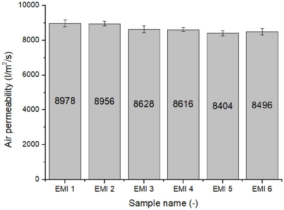
Air permeability is one of the important indicators of fabric performance, which will directly affect the comfort of clothing. The fabric with good air permeability can ensure the circulation of the internal microenvironment of the clothes and the external air environment so that the clothes will not stuffy. 35 As can be seen from Figure 5, the air permeability of sample EMI 5 is the lowest value which is 8404 l/m2/s and that of sample EMI 1 is 8978 l/m2/s which is the highest value. Since the fabric structures and fabric materials of the samples in this paper are identical and with only minor differences in the ratio of chemicals dose from the deposition step, the differences in air permeability between them are not significant. Due to the base material is a thin and porous nonwoven fabric, the samples of “Copper Plated MILIFE” are quite breathable. The relationship between air permeability and electromagnetic shielding effectiveness, air permeability and optical porosity are also studied in this paper. As the electromagnetic shielding effectiveness of the samples increases, their air permeability decreases in Figure 6(a). In contrast, as the optical porosity of the samples decreases, so does their air permeability in Figure 6(b). Regarding to the samples in this paper, the electromagnetic shielding effectiveness and air permeability are negatively correlated, and the optical porosity has a positive effect on the air permeability.
Air permeability of samples.

The relationship between EMI shielding effectiveness (a), optical porosity (b) and air permeability.
Water vapor permeability
Water vapor permeability refers to the ability of water vapor to pass through a fabric. The fabric with good water vapor permeability can effectively dissipate the sweat from the body skin into the air through the fabric pores to ensure the dryness and comfort of the body skin. 36 In this paper, relative water vapor permeability and water vapor resistance will be used to characterize water vapor permeability. Relative water vapor permeability is not according to the international standard, but it is a practical parameter. If the fabric performs decent water vapor permeability, it will has a high value of relative water vapor permeability and a low value of water vapor resistance. 31 It is apparent that sample EMI 1 with the highest relative water vapor permeability and the lowest water vapor resistance of all samples in Figure 7. In contrast, sample EMI 6 has the lowest value of relative water vapor permeability and the highest value of water vapor resistance. In addition to this, the results of the correlational analysis are set out in Figure 8. Except for sample EMI 4 which is slightly out of trend, the water vapor permeability of other samples is negatively correlated with electromagnetic shielding effectiveness and positively correlated with optical porosity. From the above analysis, the electromagnetic shielding effect will be improved with the increase of the copper plating amount, but this will lead to a decrease in the water vapor permeability due to the reduce of optical porosity.

Relative water vapor permeability (a) and water vapor resistance (b) of samples.
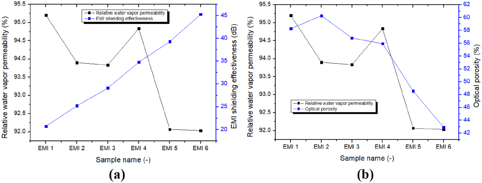
The relationship between EMI shielding effectiveness (a), optical porosity (b) and water vapor permeability.
Thermal resistance
Thermal resistance is a numerical value that expresses the ease of heat transfer. It is the value obtained by dividing the temperature difference between any two points by the heat flow (heat flow per unit time) flowing between the two points. 37 A high thermal resistance value means that heat is difficult to transfer, while a low thermal resistance value means that heat is easy to transfer. Figure 9 presents the thermal resistance of all samples, and the values are between 0.00122 and 0.00173 K m2/W. Among them, sample EMI 2 has the lowest thermal resistance, while sample EMI 4 has the highest thermal resistance. It also can be found that the data difference between samples is relatively small. The reason for that is the base material of the samples exactly the same. The small differences between the samples are mainly caused by two factors, which can be referred to the Figure 10. On the one hand, it is caused by the different copper content. Since the thermal reflectivity of metal materials is higher than that of non-metal materials, high copper content will lead to higher thermal resistance. 38 On the other hand, the volume porosity of the fabric will affect the thermal resistance. When the volume void contains a large amount of still air, the heat dissipation will be prevented, thereby increasing the thermal resistance. 39

Thermal resistance of samples.

The relationship between EMI shielding effectiveness (a), volume porosity (b) and thermal resistance.
Quality index evaluation
Except for the above analysis for each test, the paper also provides an overall evaluation of the performance of all tests using a quality index analysis method. In the first step, the local utility value u of each attribute of all samples is calculated by the following equation (3):

For a set of data under the same property test, H is the completely satisfactory test value among all samples, L is the most unsatisfactory test value among all samples, and the test value of the calculated samples is x. For example, in the local utility value of electromagnetic shielding effectiveness, where the H value is 45.3 (the completely satisfactory test value) and the L value is 20.7 (the most unsatisfactory test value), the values of x are 20.7, 25.2, 29.2, 34.8, 39.3, 45.3 respectively (data reference Table 3). The local utility values of other properties are calculated in the same way and Table 4 shows all tests’ H values and L values. In Table 5, the local utility values of all properties can be seen.
H values and L values of all tests.

Local utility value.

In the second step, the weighted geometrical average U can be calculated via the equation (4):
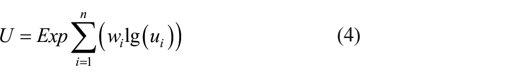
Where ui is the local utility value and wi is the weight function. The weighted geometrical average U value can be used alone as a complex quality criterion for each variant and target fabric as well. The weight function’s distribution is 25% for each test. As seen in Table 6, the values of the weighted geometrical average were calculated and also made a ranking for all samples.
Weighted geometrical average.

From the ranking in the above table, the sample EMI 4 exhibits the best results when all properties are evaluated in the quality index evaluation. The electromagnetic shielding property of the samples can be optimally balanced with their associated comfort properties when the ratio of chemicals dose in the step “Deposit” is 80%.
Conclusions
This article uses a kind of nonwoven fabric, which is electroless copper plated to obtain an electromagnetic shielding material. After evaluating its relative comfort performance, mainly study the correlation between the electromagnetic shielding effectiveness and comfort performance of the fabric, including air permeability, water vapor permeability, and heat transfer performance. First of all, based on this method of electroless copper plating, it is not difficult to find that the effectiveness of electromagnetic shielding is positively related to the amount of copper plating. Secondly, with the increasing electromagnetic shielding effectiveness, the samples’ air permeability and water vapor permeability will decrease. However, the increased electromagnetic shielding effectiveness will lead to an increase in the samples’ thermal resistance. Another important finding is the optical and volume porosities will directly affect comfort-related performance. Both air permeability and water vapor permeability have a positive correlation with optical porosity. In addition, thermal resistance also has a positive correlation with volume porosity. Finally, it can be concluded that when the ratio of chemicals dose in the step “Deposit” is 80%, the sample shows an optimal balance of the performance in all aspects. These findings contribute in several ways to our understanding of factors that influence the comfort properties of the EMI shielding fabric and provide a basis for future study. More research is required to develop a deeper understanding of the relationships between different parameters.
Footnotes
Declaration of conflicting interests
The author(s) declared no potential conflicts of interest with respect to the research, authorship, and/or publication of this article.
Funding
The author(s) disclosed receipt of the following financial support for the research, authorship, and/or publication of this article: This work was supported by the Ministry of Education, Youth and Sports of the Czech Republic and the European Union - European Structural and Investment Funds in the Frames of Operational Porgramme Research, Development and Education - project Hybrid Materials for Hierarchical Structures (HyHi, Reg. No. CZ.02.1.01/0.0/0.0/16_019/0000843).