
Abstract
The primary aim of this research is to develop thermoset composites reinforced with cotton fibres extracted from textile waste. These composites are mainly targeted to replace timber in its application for furniture items and in some visible and non-visible automotive components. The pre-consumer cotton textile wastes such as cutting waste, in garment manufacturing, and defective fabrics were converted into the fibrous form called ‘shoddy’, using rag-tearing technique. The fibrous web of shoddy was produced using the carding machine. This web was used for developing thermoset composites as a reinforcement material. The thermoset composites with four different fibre volume fraction values, namely 0.1, 0.2, 0.3 and 0.4 were developed using compression moulding technique. The developed composites were characterised by mechanical properties, dynamic mechanical properties, thermal degradation behaviour and water absorption behaviour. The mechanical properties of the composites were found comparable with that of commercial wood. These composites can be used to develop a dashboard panel. The composites developed in this research have shown low water diffusion coefficient values as compared with pine, oak and linden wood.
Introduction
Textile waste–reinforced composites are gaining more attention in recent times. Particularly, the waste cotton fibre- or fabric-reinforced thermoset and thermoplastic composites have been reported. The global volume share of cotton was 31% in 2015 and 25.4% in 2016.1,2 Also, the increasing demand for cotton textiles and the simultaneous increase in the quantity of waste makes the world to think about recycling waste textiles. 3 The waste textiles can be successfully employed to develop composite boards for applications like furniture materials, subflooring, roofing materials, support for outdoor signs, automotive components and so on.4–6
Umar et al. 7 reported two different types of woven fabrics as reinforcement for thermoset composites. The reinforcement materials consist of cotton yarn, used as warp, and the yarn produced from comber noil and knitting waste, used as weft. However, they developed laminated composites which may fail by delamination. 8 Kotliar 4 developed thermoset phenol formaldehyde composites reinforced with shredded fibres obtained from carpet waste, fabric waste, cotton socks and wood fibres obtained from hardwood. He concluded that proper placement of fibres in the composite can help in obtaining superior mechanical properties and these composites can produce wood-like properties. Although Binici et al. 5 reported that the composite boards developed from the combination of sunflower stem, stalk fibres and cotton fibres as reinforcement and epoxy resin as a matrix have high thermal conductivity coefficient value compared with the composite boards which were developed using same reinforcement and gypsum as a binder, they did not use fibres recovered from textile waste. Furthermore, Kotliar 4 and Binici et al. 5 did not study the water absorption behaviour of the developed composite boards. Many other studies have reported textile waste, namely cotton-, wool-, silk- and polyester fibres–reinforced thermoplastic composites.9–13
India is the largest producer of cotton fibres. Therefore, a huge quantity of cotton fibres is available. The cotton fibre–reinforced composites are green since cotton is a biodegradable component. Furthermore, this research reports the application of cotton fibres extracted from textile waste generated in the textile industry for the development of thermoset epoxy composites. Therefore, the developed composites are sustainable, green and environment-friendly. Furthermore, the carding speed to produce a fibre web was optimised, to realise the maximum tensile strength of the fibres. The mechanical properties such as tensile strength, Young’s modulus and flexural and izod impact strength of the developed composites were studied. The viscoelastic behaviour of the composites was studied by dynamic mechanical analysis (DMA) for the automotive components application. To understand the thermal stability, the thermogravimetric behaviour of the composites was carried out. Furthermore, the water absorption behaviour of the composites was characterised by determining equilibrium water content and water diffusion coefficient.
Experiments
Cotton shoddy web and epoxy resin
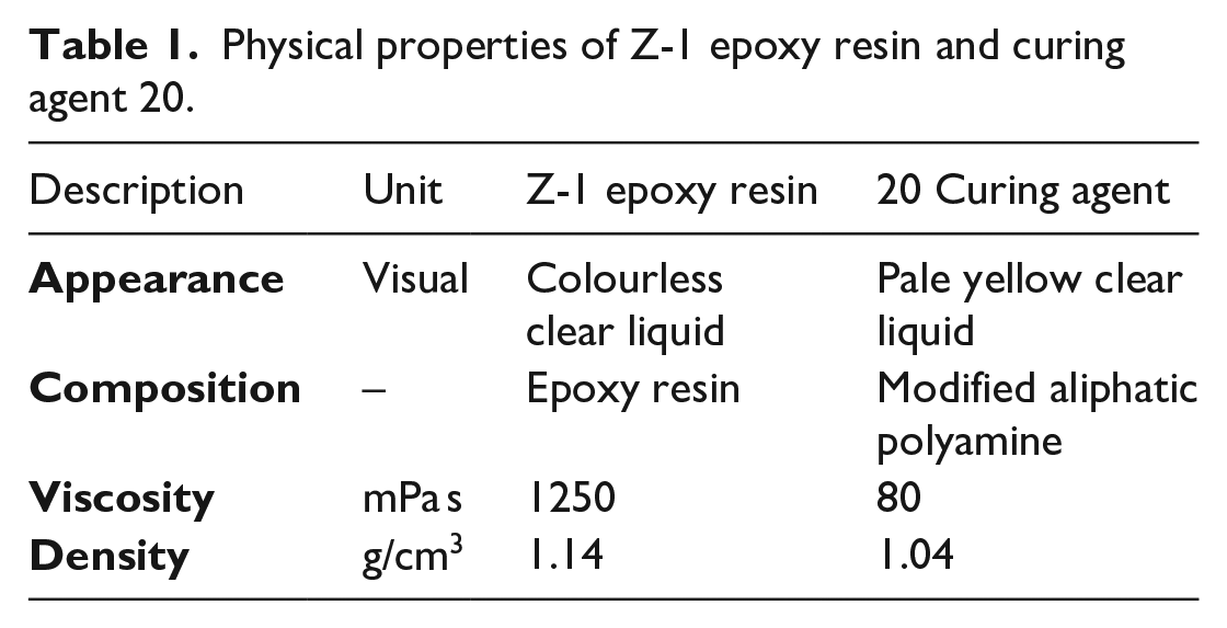
As a reinforcement material, pre-consumer cotton textile wastes such as cutting waste in garment making and defective fabrics were collected from the textile industry. Those textile wastes were processed in the rag-tearing machine to extract the fibres. These extracted fibres from waste textiles are called ‘shoddy’. Figure 1(a) and (b) shows the image of cotton shoddy obtained after the rag-tearing process and its microscopic view, respectively. The cotton shoddy web was produced using a carding machine. Later, this web was used as a preform for thermoset composite development. The thermoset epoxy resin Z-1 and curing agent 20 used as matrix material were supplied by Nissin Resin Corporation Limited, Japan. Table 1 shows the physical properties of the epoxy resin and curing agent.
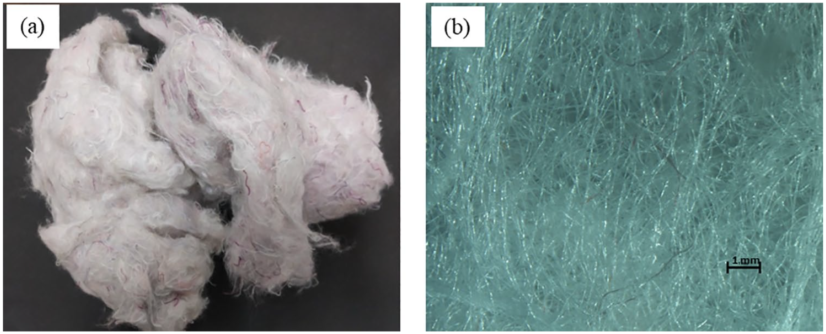
(a) Cotton shoddy obtained after rag-tearing process and (b) its microscopic view.
Physical properties of Z-1 epoxy resin and curing agent 20.
Preparation of carded web and development of thermoset composites
The carding speed has a significant role in fibre orientation. The mechanical properties of the composites in particular direction are decided by the orientation of fibres in that direction. 14 Therefore, the cotton shoddy was processed on roller carding machine at different cylinder speeds, that is, 100, 150, 200 and 250 r/min to optimise the speed. The working width of the carding machine was 30 in. The fibre web delivered by carding machine was subsequently wound onto the wooden roller to develop multilayer web.
The cotton shoddy web with desired dimensions and precise weight as per fibre volume fraction was taken. The epoxy resin and curing agent were mixed together in a weight proportion of 100:25 as per the manufacturer’s guidelines. The epoxy resin mixed with hardener was degassed for alleviating air bubbles before applying it on to the fibre web. The cotton shoddy web was placed into the mould and subsequently, the resin was applied. During the resin application, care has been taken to ensure proper fibre wetting. Compression moulding technique was used to develop composite specimens. The cotton shoddy webs produced with different cylinder speeds were converted to thermoset composites. The developed composites were characterised by tensile test to identify the optimum carding speed. The cotton shoddy web produced with optimised carding speed was then used to develop thermoset composites. The composites with four different fibre volume fractions, namely 0.1, 0.2, 0.3 and 0.4, and each with 3-mm thickness, were developed. The composites were cured at 120°C temperature for 20 min. Figure 2 shows the stepwise process of composite development.
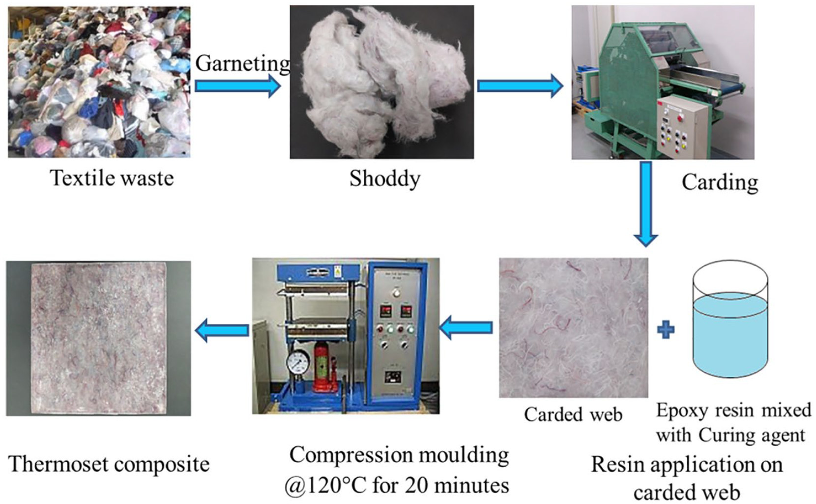
Stages in composite specimen development from textile waste.
Characterization of mechanical properties of the composite specimens
The composite specimens were characterised according to ASTM D3039, ASTM D7264 and ISO 180:2000 standards for tensile strength, three-point bending strength and notched izod impact strength, respectively. The dimension of composite specimens for the tensile test was 250 mm × 25 mm × 3 mm. The composite specimens with the span-to-thickness ratio of 32:1 and 96-mm span length were prepared for the flexural strength test. The notched izod impact strength test was performed with specimen dimensions 80 mm × 10 mm × 3 mm. Five specimens each for tensile, flexural and notched izod impact test were tested to determine the mean value.
Dynamic mechanical properties and thermogravimetric analysis of the composite specimens
The viscoelastic behaviour of composite specimens was studied using dynamic mechanical analyser. The specimen having dimensions 36 mm
Scanning electron microscopy
The fractured surfaces of the composite specimens were coated with gold particles under the vacuum of 0.01 mbar using a sputter coater before scanning electron microscope (SEM) analysis. The tensile and izod impact fractured surfaces were imaged using a SEM at 20 kV acceleration voltage. The images of fractured surfaces of the composite specimens were analysed to understand the failure modes of the composites.
Determination of water uptake and water diffusion coefficient
The water absorption test was performed according to ASTM D570 standard. The specimens were weighed before placing into water. The specimens were then immersed into distilled water at room temperature. At regular time interval of 24 h, the specimens were taken out of the water and wiped with a cotton cloth before weighing. The specimen weighing was performed within 30 s to avoid any error due to evaporation. This procedure was repeated until the specimen became saturated by water. The water uptake (WC) by the composite was determined using the following equation
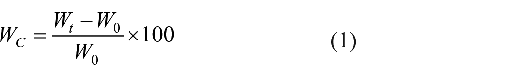
where Wt is the weight of the specimen at time t and W0 is the initial weight of the specimen before placing into water. 15
The diffusion coefficient (D) is measured as the slope of the initial part of weight gain versus square root of time curve and it is calculated using equation (2)

where Mt and M∞ are the weight of water content at time t and equilibrium water content, respectively. L is the sample thickness and D is the diffusion coefficient. 15
Results and discussion
Effect of carding speed on tensile strength of the composites
Figure 3 shows the effect of different cylinder speeds on maximum tensile stress. Furthermore, with an increment of cylinder speed from 100 to 250 r/min no significant change in the maximum tensile stress of the composites in the machine direction was observed. The maximum tensile stresses in the machine direction are 65.19, 65.2, 65.75 and 65.25 MPa for cylinder speeds 100, 150, 200 and 250 r/min, respectively. The maximum tensile stresses in the cross-machine direction are 40.69, 42.14, 44.63 and 46.14 MPa for cylinder speeds 100, 150, 200 and 250 r/min, respectively. Therefore, 200 r/min cylinder speed was chosen to produce carded web to study the mechanical properties of composites by varying fibre volume fraction.

Effect of cylinder speed on maximum tensile stress of the composite.
Effect of fibre volume fraction on tensile, flexural and izod impact strength of composites
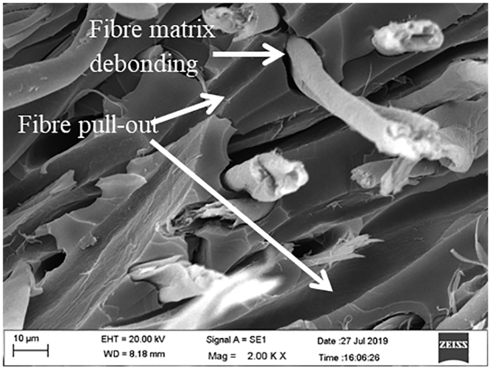
The tensile strength and Young’s modulus of the composites changes with change in fibre volume fraction. As shown in Table 2 with an increment of fibre volume fraction from 0.1 to 0.3, the maximum tensile stress on composite increased from 49.47 to 83.74 MPa. A similar trend was observed for Young’s modulus which increased from 1.5 to 2.4 GPa for 0.1–0.3 fibre volume fraction, respectively. However, a reverse trend was observed for the maximum tensile stress when the fibre volume fraction reached 0.4. The maximum tensile stress was dropped to 75.43 MPa. However, Young’s modulus increased to 3.3 GPa. The higher fibre volume, that is, 0.4 fibre volume fraction caused improper resin flow within the preform which led to the formation of the void within the composite. The typical load elongation curves of the composites reinforced with different fibre volume fractions are shown in Figure 4 indicating an increase in the breaking elongation of the composite with an increase in fibre volume fraction. It was observed that the composite fails by fibre breakage, fibre matrix debonding and fibre pull-out as shown in Figure 5(a) and (b). The probable reason for fibre pull-out and fibre matrix de-bonding is the weak interface between fibre and matrix.
Mechanical properties of composites reinforced with different fibre volume fractions.


Load-elongation curves of composites with different fibre volume fractions.

Scanning electron microscope images of the tensile fractured specimen showing (a) fibre pull out and (b) fibre matrix debonding.
As shown in Table 2 with an increment of fibre volume fraction from 0.1 to 0.4, the maximum flexural stress increased from 46.42 to 108.38 MPa. This is attributed to increased fibre–matrix interface area with an increase in fibre volume fraction which results in higher load transfer from matrix to the fibre. With an increase in fibre volume fraction from 0.1 to 0.2, 0.2 to 0.3 and 0.3 to 0.4, the maximum flexural stress increased by 38.11%, 30.39% and 29.67%, respectively. The typical load–deflection curves of the composite specimen with different fibre volume fractions are shown in Figure 6. It can be seen from Figure 6 that the deflection at maximum load is approximately the same for the composites with different fibre volume fractions. The flexural modulus values of the composite specimens with 0.1, 0.2, 0.3 and 0.4 fibre volume fraction were 1.93, 3.93, 4.58 and 6.99 MPa, respectively. The decrease in the percentage improvement of maximum flexural stress with an increase in fibre volume fraction can be attributed to the increased void content within the composite. It has been observed that with an increment of fibre volume fraction from 0.1 to 0.4, the izod impact strength increased from 2.13 to 7.62 kJ/m2, respectively. The percentage improvement in izod impact strength with an increase in fibre volume fraction from 0.1 to 0.2, 0.2 to 0.3 and 0.3 to 0.4 was 85.13%, 69.88% and 13.82%, respectively. As shown in Figure 7, the composite failure due to izod impact test was mainly due to fibre breakage and fibre pull-out. Furthermore, the fibres which are parallel to the direction of applied force are pulled out since they did not take part in load-bearing. The mechanical properties of the developed composites are comparable with that of commercial wood. 16 A composite to be used as automotive dashboard panel should have density, Young’s modulus and a tensile strength greater than 1.18 g/cm3, 2.3 GPa and 25 MPa, respectively. 17 Therefore, the composites with 0.3 and 0.4 fibre volume fractions are potential materials for automotive dashboard panel manufacturing.

Load–deflection curves of composites with different fibre volume fractions.
Scanning electron microscope image of izod impact fractured specimen.
Dynamic mechanical analysis of composites with different fibre volume fractions
As shown in Figure 8(a), the storage modulus of composite specimens at room temperature was increased from 2537.42 to 4188.30 MPa, with an increment of fibre volume fraction from 0.1 to 0.4, respectively. This is attributed to the reinforcement of composite by cotton fibres. The storage modulus values at room temperature for composites with 0.2 and 0.3 fibre volume fraction were 2847.17 and 3967.29 MPa, respectively. Furthermore, Figure 8(a) shows that while the temperature increased the storage modulus decreased and at a temperature near 50°C, the storage modulus started falling steeply. The composite specimens having fibre volume fractions 0.1, 0.2, 0.3 and 0.4 showed storage modulus values of 105.06, 260.45, 694.22 and 1265.79 MPa, respectively, at 100°C. The damping factor (tan delta) decreased with an increment in fibre volume fraction which is shown in Figure 8(b). This is because with an increase in fibre volume fraction the fibre–matrix interfacial bonding increases and therefore polymer molecular mobility reduces. 18 The tan delta peak values for composites with 0.1, 0.2, 0.3 and 0.4 fibre volume fraction are 0.629, 0.478, 0.325 and 0.207, respectively. Thus, the composite with 0.4 fibre volume fraction is more elastic compared with rest of the composites. The glass transition temperatures are 75°C, 72.03°C, 88.73°C and 88.43°C for composites with 0.1, 0.2, 0.3 and 0.4 fibre volume fraction, respectively.

(a) Storage modulus and (b) tan delta plot of composites with different fibre volume fractions.
TGA of composites with different fibre volume fractions
The TGA gives information about the thermal stability of the composite materials. Figure 9 shows a very small change in the weight of the composite at the start of the TGA test. This is attributed to evaporation of water present in the cotton fibres within the composite. The maximum weight loss rate for all composites was observed between temperatures 250°C and 450°C. This is associated with thermal decomposition of cellulose in the fibres which occurs between temperatures 255°C and 340°C. 19 The half weight loss temperature for composites with 0.1, 0.2, 0.3 and 0.4 fibre volume fraction were 374°C, 373°C, 367°C and 368°C, respectively. It has been observed that the char yield of composites increased with an increment in fibre volume fraction. The char yield of 99.11%, 98.54%, 99.24% and 98.94% was observed for composites with 0.1, 0.2, 0.3 and 0.4 fibre volume fraction, respectively, at 100°C. The TGA confirms that the developed composites are thermally stable.

Thermogravimetric analysis of composite specimens reinforced with different fibre volume fractions.
Water absorption behaviour of composites reinforced with different fibre volume fractions
The natural fibre–reinforced composites have poor moisture resistance. This is because of moisture absorption by natural fibres due to hydroxyl and polar groups. Three mechanisms are reported which govern the water diffusion in polymer composites. First is by diffusion of water into the micro-gaps between adjacent polymer chains, second is by capillary action into the gaps at the fibre–matrix interface and the third is by transport through micro-cracks in the matrix. The interfacial adhesion between fibres and matrix gets reduced after moisture absorption by fibres, which results in the reduction of the mechanical properties of the composite.20,21 The composites developed in this research showed water absorption requires 7 days to reach equilibrium. A negligible amount of water was absorbed by the composite on the seventh day, which is shown in Figure 10. As a consequence, no significant increase in weight gain percentage of the composite specimens was observed on the seventh day. Moreover, it can be seen from Figure 10 that the water uptake by the composites increases with an increment of fibre volume fraction. Higher the natural fibre content in the composite higher will be the water uptake. 20 The equilibrium water content of the composites increases with an increment in fibre volume fraction as shown in Table 3. From Table 3, it can be observed that the diffusion coefficient of the composite decreases with an increase in fibre volume fraction. Interestingly, all the composites show a low value of diffusion coefficient compared with pine, oak and linden wood. 22

Change in the weight gain percentage of water-immersed composite specimen having different fibre volume fractions with time.
Water uptake characteristics of composites with different fibre volume fractions.

Conclusion
The fibres recovered from textile waste were successfully employed to reinforce the composite materials. The storage modulus of the developed composites increased with an increase in fibre volume fraction, in addition, the damping factor decreased. The equilibrium water content of the composites increased with an increment in fibre volume fraction. Since the developed composites show a char yield of approximately 99% at 100°C, it can be considered as thermally stable. The composites developed in this research exhibited the required mechanical properties to be used in items of furniture material and some visible and non-visible automotive components. Thus, the developed composites may successfully replace timber in furniture applications. Therefore, textile waste–reinforced composites could be safely considered as a sustainable material.
Footnotes
Declaration of conflicting interests
The author(s) declared no potential conflicts of interest with respect to the research, authorship and/or publication of this article.
Funding
The author(s) received no financial support for the research, authorship and/or publication of this article.