
Abstract
The present research reports thermoset nanocomposites reinforced with cotton fibres extracted from textile waste called as ‘shoddy’ and graphite oxide nanoparticles as filler. The oriented fibre web of shoddy was produced by using the carding machine and it was used as reinforcement. The thermoset epoxy composites with four different fibre volume fraction values namely 0.1, 0.2, 0.3 and 0.4 were developed. These composites were characterized by mechanical properties to optimize the fibre volume fraction. Further, thermoset epoxy nanocomposites were developed by incorporating graphite oxide nanoparticles as filler in four different weight percentages, namely 0.1, 0.3, 0.5 and 1%. All the composites were characterized for mechanical properties, dynamic mechanical properties, thermal degradation behaviour and water absorption behaviour. It has been found that the developed composites can be used in items of furniture materials and to develop some visible and non-visible automotive components.
Keywords
Introduction
Textiles are the second most important need of a human being to live and be protected from different weather conditions. However, with increasing population, the consumption of textiles increased and subsequently the textile waste increased. The linear way of operating textile system has laid the world to face a serious issue of sustainable textile waste management. The textile wastes are broadly classified as pre-consumer waste and post-consumer waste. The textile waste generated during textile manufacturing are pre-consumer wastes, whereas the post-consumer wastes are those who have served their useful life [1,2].
Kotliar [3] developed thermoset phenol formaldehyde composites reinforced with shredded fibres extracted from carpet waste, fabric waste, cotton socks and wood fibres obtained from hardwood. He concluded that by the proper placement of fibres in the composite, superior mechanical properties can be obtained and these composites can produce wood-like properties. A study conducted by Binici et al. [4] shows that the boards developed from sunflower stem and stalk fibres, cotton fibres as reinforcement and epoxy resin as a binder, have high thermal conductivity coefficient value compared to the boards developed by using the same reinforcement and gypsum as a binder. Zonatti et al. [5] developed composites by employing fibres recovered from denim as reinforcement and three types of matrix materials namely thermoset epoxy, ortophtalic unsaturated polyester and polyurethane. These composites were developed for fashion accessories applications. Telem Gok Sadikoglu et al. [6] reported that the urea-formaldehyde composites reinforced with polyester textile waste can be used to replace fibreboard and medium-density fibreboard. Alamri and Low [7] developed thermoset epoxy composites reinforced with recycled cellulose fibre (RCF) paper. Their study shows that flexural strength, fracture toughness and Charpy impact strength in dry and wet conditions increase with an increase in RCF content. Many studies reported that thermoset composites reinforced with different fibre wastes such as sugarcane bagasse fibres [8], disposable chopsticks fibres [9,10], palm oil empty fruit bunch fibre [11], etc.
The mechanical properties of the epoxy composites get improved upon the addition of the graphite oxide as filler. Graphite oxide is obtained by the oxidation of graphite flakes [12]. Yan-Jun Wan et al. [13] reported a 35% rise in tensile strength of epoxy composite as compared to neat epoxy at 0.1 wt.% of graphite oxide loading. Long-Cheng Tang et al. [14] developed epoxy composites reinforced with reduced graphene oxide (rGO). They developed rGO by thermal exfoliation of graphite oxide. Their study shows a slight improvement in the tensile and flexural strength of epoxy composites upon rGO loading. However, they observed significant improvement in elastic and flexural modulus with an increment of rGO loading. A similar study by Wei et al. [15] for epoxy composites filled with graphene shows an increase in tensile and flexural strength, tensile and flexural modulus with an increment of graphene loading. Rafiee et al. [16] developed graphene platelets, which are multiple graphene sheets stacked together, filled with epoxy composites. Their study shows a 40% increase in tensile strength of nanocomposites at 0.1 wt.% of graphene platelets loading. The tensile strength of epoxy composites filled with graphene platelets was found higher than a single wall and multi-wall carbon nanotubes. Tshai et al. [17] concluded that an increase in the tensile and flexural strength of the natural fibre reinforced thermoset composites with the addition of nano-graphene as a filler. The thermal degradation behaviour of natural fibre reinforced composites filled with graphene or graphene oxide nanoparticles is superior compared to composites without filler [17,18]. The textile waste reinforced thermoset composites filled with graphite oxide filler are not reported much.
It has been anticipated that the total textile waste in 2030 will be 148 million tonnes which would be 17.5 kg per capita per year across the planet. Also, more than 150 million tonnes of waste textiles would be landfilled or burned in 2050 [19]. In the US, 21 billion tonnes of municipal solid textile waste is being generated every year. Around 0.3 million tonnes of used clothing is been landfilled in the UK every year. An estimate of 16 million tonnes per year of textile waste is being generated by the European textile industry [2]. Brazil produces 0.175 million tonnes of textile industry residue per year [5]. Thus, the textile waste management will be a serious problem globally in the near future. Therefore, efforts need to recycle these waste textiles. Studies reported nonwoven fabrics developed from textile waste for applications such as sound insulation [20], thermal insulation [21,22], agricultural mulching [23]. Panipat city in India is one of the biggest textile waste recycling hub, where they produce spun yarn using the fibres extracted from waste textiles. Further, this yarn is used to develop school blazer fabrics, drapes, doormats, prayer rugs, blankets, bedsheets, etc. [24] The cotton fibre waste and some plant fibres materials are used to produce paper. The fibres which are too short can be used as an additive in construction materials. [25] The waste textiles are also used for energy recovery by pyrolysis. [26] However, pyrolysis process emits hazardous gasses. Textile waste reinforced composite is one of the unique products to efficiently realise the true potential of waste textiles. The present research reports extraction of cotton shoddy from waste textiles, production of carded web and then developing thermoset composites using the carded web as reinforcement. No other study reports a similar type of composites development process as per the best of author’s knowledge. Furthermore, the addition of graphite oxide nanoparticles improves the mechanical and thermal properties of the waste textiles-reinforced composites. These composites can be used for applications such as items of furniture materials, automotive components, etc. Thus, the cotton textile waste can be upcycled for higher end applications which ultimately results in a reduction of tree cuttings and virgin materials consumption. Therefore, this study is focused on the development of composite materials reinforced with cotton textile wastes and filled with graphite oxide nanoparticles. This study reported addition of GO content on the weight of fibres in the composites. Whereas many other studies reported the addition of GO content on the total weight or total volume of the composite. Further, these composites were characterized for mechanical properties, dynamic mechanical properties and thermogravimetric analysis (TGA). The water absorption behaviour of the composites was also studied to determine the equilibrium water content, the water diffusion coefficient, water transmission rate, absorption coefficient and permeability coefficient.
Materials and methods
Materials
The cotton shoddy was used as reinforcement material for composite making. The cotton shoddy is a fibrous form obtained by tearing away cotton fabric waste by using the rag-tearing machine. The cotton shoddy obtained after the rag-tearing process and its microscopic view are shown in Figure 1. The thermoset epoxy resin Z-1 and curing agent 20 supplied by Nissin Resin Corporation Limited Japan were used as a matrix for composite specimen preparation. The physical properties of the epoxy resin and curing agent are shown in Table 1. The graphite oxide (GO) nanoparticles were purchased from ACS materials, Canada and they were used as supplied. The purchased graphite oxide is manufactured by using the modified Hummer’s method and the particles were 1–3 nm thick and having diameter of 0.5–5 μm.
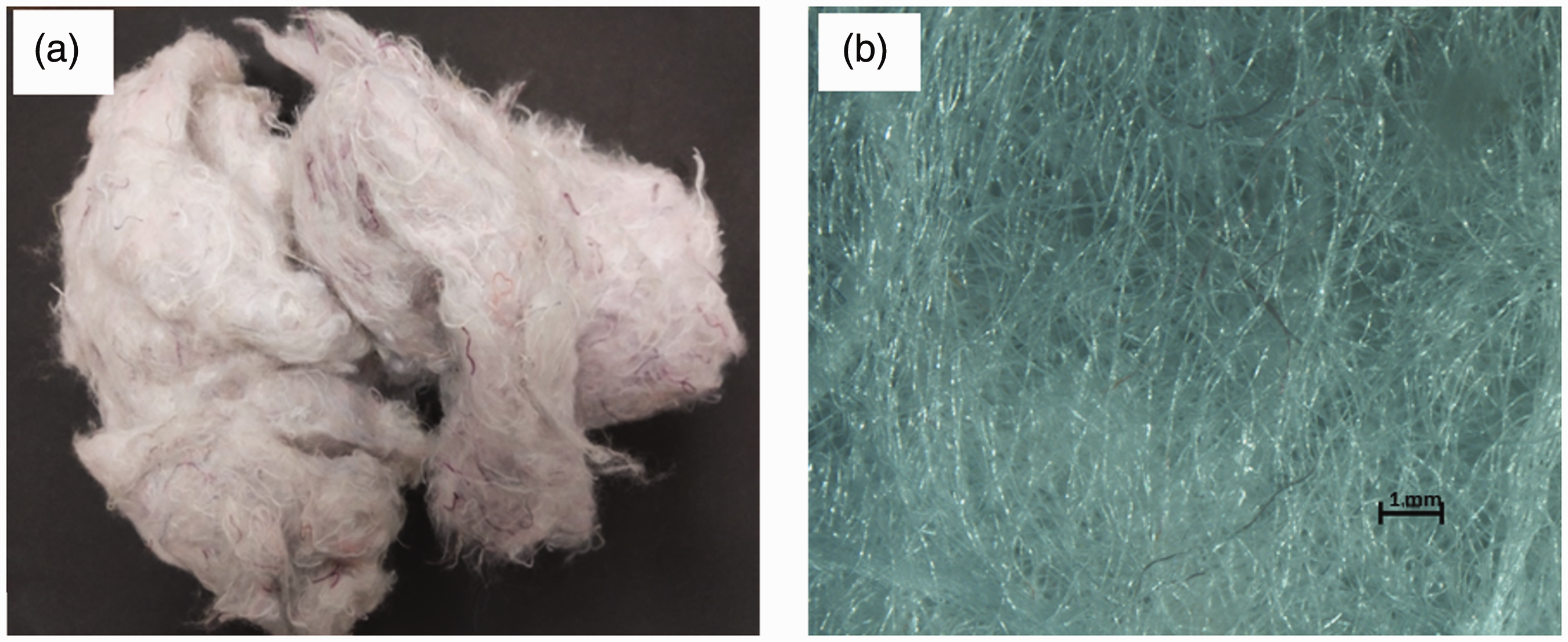
Cotton shoddy obtained after rag tearing (a) and its microscopic view (b).
Physical properties of Z-1 epoxy resin and 20 curing agent.

Preparation of carded web
The shoddy was processed on roller carding machine at 200 r/min of the cylinder to produce fibre web. The single-layer of fibre web, produced by using the carding machine as shown in Figure 2, has an average areal density of 27 g/m2. The web areal density is measured by using the ASTM D3776-96 standards. The fibre web delivered by a carding machine was subsequently wound onto a wooden roller to get a multilayer web. The top and the cross-sectional view of the multi-layered carded web is shown in Figure 3(a) and (b), respectively. The multilayer web was used as a preform for the thermoset composite specimen production.

A piece of a single layer of the fibre web.

Top view (a) and cross-sectional view (b) of the multi-layered carded web.
Development of thermoset composites
The stainless steel mould having dimension of 25 cm × 20 cm × 0.3 cm was fabricated. According to the mould’s dimension, the multilayer fibre web was first cut. The web weight as per fibre volume fraction desired in the composite was taken. The detailed method of determination of fibre and resin weight according to the desired fibre volume fraction in the composite is described in the supplementary Appendix. Here, it must be noted that the carded web areal density is independent of composite fibre volume fraction. The weighted multilayer web was then divided into six parts having an equal number of layers. The epoxy resin and curing agent were mixed in a weight proportion of 100:25 as per the manufacturer guidelines. The epoxy resin mixed with hardener was degassed for alleviating any air bubbles before applying it on to the fibre web. The cotton shoddy web was placed into the mould and subsequently, the resin was applied. The care has been taken to ensure uniform fibre wetting during the resin application. The thermoset composites with four different fibre volume fractions namely 0.1, 0.2, 0.3 and 0.4 and having 3 mm thickness were produced. All the composite specimens were produced by using a compression moulding technique. The vacuum-assisted resin infusion technique is not suitable for the preform in the web form, because the fibre orientation gets disturbed during resin infusion. Any change of fibre orientation will directly influence the mechanical properties of composite [27]. The composites were cured at 120°C temperature for 20 min, as per the manufacturer’s guidelines. The process of composite specimen manufacturing is shown in Figure 4.
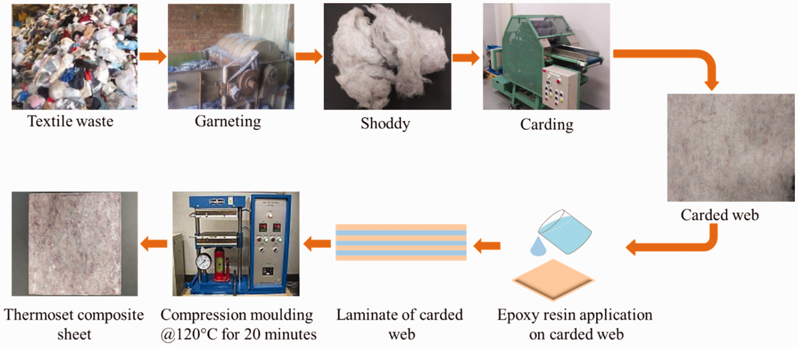
Stages in composite specimen manufacturing from textile waste.
Development of thermoset nanocomposites
To incorporate the GO nanoparticles into the composite, a weighed quantity of GO nanoparticles was first sonicated in the hardener for 1 h. The hardener was then mixed with epoxy resin as shown in Figure 5. The resin and hardener were further mixed by hand stirring and then degassed to alleviate any air bubbles before applying it on to the fibre web. The composites were produced by using the compression moulding technique and the making process of the composites was same as explained above. The thermoset nanocomposites with four different GO contents namely 0.1, 0.3, 0.5 and 1.0% on the weight of fibres in the composite were developed. The fibre volume fraction and thickness of all nanocomposites were 0.3 and 3 mm, respectively.
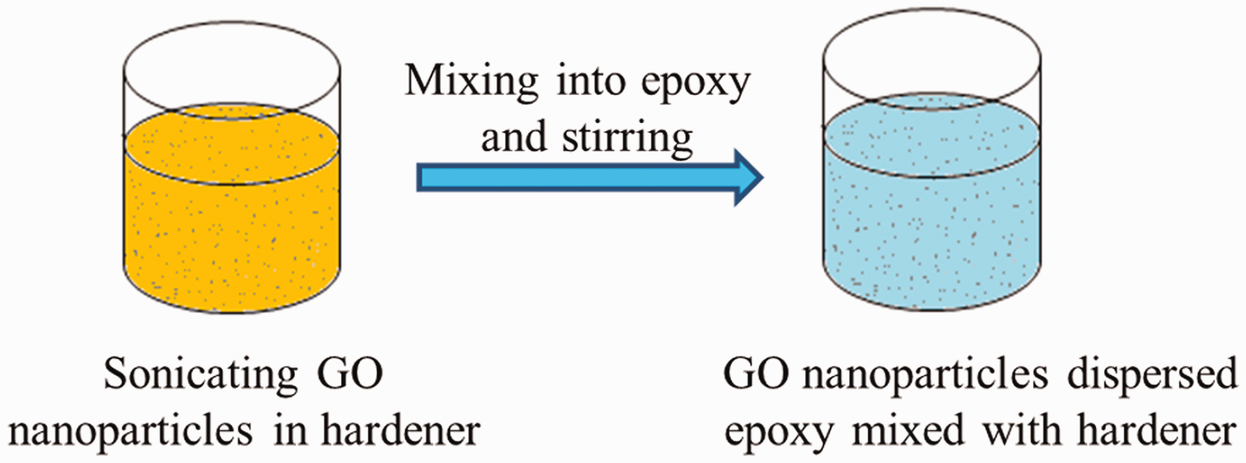
Process of GO nanoparticles exfoliation and dispersion into the epoxy resin.
Characterization of composite specimens for mechanical properties
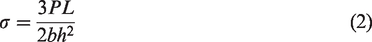
The composite specimens were characterized by tensile, three-point bending and notched izod impact strength properties. These tests were performed to appraise the suitability of these composite materials in applications such as items of furniture materials and automotive components, etc. The tensile properties of composite specimens were characterized according to the ASTM D3039/ASTM D3039M standards [28]. The composite specimen for a tensile strength test having dimension of 250 mm × 25 mm × 3 mm was tested on Autograph universal strength tester. The maximum tensile stress, breaking elongation and Young’s modulus were determined. The maximum tensile stress (σmax) was determined by using equation (1)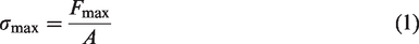
Further, the composite specimens were characterized by notched izod impact strength test according to the ISO 180:2000 standards [30]. The tests were performed on Toyoseiki digital impact tester with specimen dimensions of 80 mm × 10 mm × 3 mm. The notched izod impact strength is determined by using equation (4)

Dynamic mechanical analysis
The viscoelastic behaviour of composite specimens was studied by using the dynamic mechanical analyser. The specimen of dimension 36 mm × 13 mm × 3 mm were tested in single cantilever mode by using the frequency scan ranging from room temperature to 250°C at a 10 Hz frequency and temperature ramp rate of 5°C per minute.
TGA
The TGA of composite specimens and neat epoxy resin was performed on the thermogravimetric analyser to understand the thermal response of the composites. The composite and epoxy resin specimens of weight 6–9 mg were used for the test. The tests were performed for the temperature range of room temperature to 800°C at a constant heating rate of 10°C per minute in a nitrogen atmosphere.
Water absorption test
The composite specimens were characterized by a water absorption test according to the ASTM D570-98 standards [32]. The composite specimens with dimensions 25 mm × 25 mm × 3 mm were cut from the developed composite sheet [33]. The specimens were weighed before subjecting to moisture absorption. The specimens were then immersed into distilled water. At regular interval of 24 h, the specimens were removed from the water and wiped with a cotton cloth to remove the surface water and then weighed. The specimen weighing was performed within 30 s to avoid any error due to evaporation. This procedure was continued until the specimens get saturated by water. The water uptake (WC) by the composite is determined by using equation [33] (6)


All sides of the specimen were exposed to water, and therefore the total surface area (TSA) of the specimen was considered in WTR.
Venkateshwaran et al. [35] reported that the water permeability of the composites is dependent on the absorption of water by the fibres. They measured water permeability in terms of absorption coefficient (S) and it is calculated by using equation (9)

Scanning electron microscopy
The tensile and izod impact fractured surfaces of the composite specimens were analysed for fibre and matrix interface and the failure modes of the composites by using a Zeiss EVO18 scanning electron microscope at 20 kV acceleration voltage.
Results and discussion
Effect of fibre volume fraction on mechanical properties of the composites
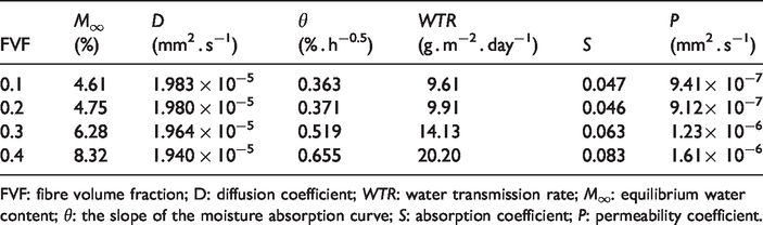
The tensile properties of the composites change with the change in fibre volume fraction. As shown in Table 2, it can be observed that as the fibre volume fraction increases from 0.1 to 0.3, the maximum tensile stress on composites increases from 49.47 MPa to 83.74 MPa and the Young’s modulus increases from 1.5 GPa to 2.4 GPa, respectively. However, when the fibre volume fraction further increases to 0.4, the maximum tensile stress decreases to 75.43 MPa and the Young’s modulus increases to 3.3 GPa. The higher fibre bulk at 0.4 fibre volume fraction causes improper resin flow within the reinforcement which leads to the formation of the void within the composite. The void volume of 5.33, 6.05, 9.98 and 12.85% was observed for composites with 0.1, 0.2, 0.3 and 0.4 fibre volume fraction, respectively. It has also been observed that the composite fails by the fibre matrix de-bonding, fibre pull-out and fibre breakage as shown in Figure 6(a) and (b). The probable reason for fibre matrix debonding and fibre pull-out is the weak interface between the fibre and the matrix. The load-elongation curves of the composites with different fibre volume fractions are shown in Figure 7. The breaking elongation of the composites increases with an increase in the fibre volume fraction.
Mechanical properties of the composites with different fibre volume fractions, industrial particleboards and rubberwood/epoxy composites.


Scanning electron microscope images of the tensile fractured specimens showing fibre pull-out (a) and fibre–matrix debonding (b).

Load-elongation curves of composites with different fibre volume fractions.
The load–deflection curves of composites with different fibre volume fractions are shown in Figure 8. It can be observed from Figure 8that with an increase in fibre volume fraction, the maximum flexural load experienced by the composite increases. Also, as shown in Table 2, with an increase in fibre volume fraction from 0.1 to 0.4, the maximum flexural stress increases from 46.42 MPa to 108.38 MPa. This is attributed to an increase in the fibre volume fraction as the fibre–matrix interface area increases and therefore the load transfer from matrix to the fibre increases. As fibre volume fraction increases from 0.1 to 0.2, 0.2 to 0.3 and 0.3 to 0.4, the maximum flexural stress increases by 38.11%, 30.39% and 29.67%, respectively. The decrease in the percentage improvement of maximum flexural stress with an increase in fibre volume fraction may be due to the increased void content within the composite. It has been observed that as the fibre volume fraction increases from 0.1 to 0.4, the izod impact strength increases from 2.13 KJ/m2to 7.62 KJ/m2, respectively. The percentage improvement in izod impact strength with an increment in fibre volume fraction from 0.1 to 0.2, 0.2 to 0.3 and 0.3 to 0.4 is 85.13%, 69.88% and 13.82%, respectively. The failure of the composites under impact load was majorly due to fibre pull-out and fibre breakage as shown in Figure 9.

Load–deflection curves of composites with different fibre volume fractions.

Scanning electron microscope image of izod impact fractured specimen.
Effect of graphite oxide content on mechanical properties of the nanocomposites
It has been observed that the addition of GO nanoparticles improves Young’s modulus and maximum tensile stress of the composites. The crack deflection is the mechanism of strength improvement by the addition of graphene platelets in epoxy composites. The crack deflection is the process in which the initial crack gets tilted or twisted due to the presence of nanoparticles during tensile loading [16]. The GO nanoparticles along with the cotton fibres bear the load transferred by matrix. Additionally, the GO nanoparticles help to tilt or twist the crack encountered and thus the overall strength of the composite increases. The Young’s modulus of the nanocomposites was found increasing with an increase in GO content. The load-elongation curves of the composites with different GO contents are shown in Figure 10. The breaking elongation of the composite specimens was found nearly similar. As shown in Table 3, no trend has been observed for an increase in maximum tensile stress of the composites filled with four different weight percentages of GO nanoparticles. The exfoliated and agglomerated GO sheets observed in TEM image are shown in Figure 11. This agglomeration of GO nanoparticles leads to weak interaction with the epoxy matrix [17]. However, the maximum tensile stress for the composite specimens without GO and with 1% GO was 83.75 and 90.18 MPa, respectively.

Load-elongation curves of composites with different GO contents.
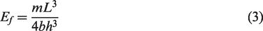
Mechanical properties of composites with different GO contents.

TEM image of exfoliated GO sheets (a) and agglomerated GO sheets (b).
As shown in Table 3, as GO content increases from 0 to 0.3%, the maximum flexural stress increases from 83.58 MPa to 106.54 MPa, respectively and then decreases for 0.5 and 1% GO content. The addition of GO nanoparticles leads to an increased matrix interface, which results in higher load transfer from the matrix to the reinforcement. However, due to an increase in the agglomeration of GO nanoparticles for 0.5 and 1% content, the interaction of GO with the epoxy matrix weakens and thus the flexural stress decreases. The load–deflection curves of composites filled with different GO contents are shown in Figure 12. It can be observed from Figure 12that the flexural load experienced by the composite filled with GO is higher than the composite without GO. As shown in Table 3, as the GO content increases from 0 to 0.3%, the izod impact strength increases from 6.69 to 6.94 KJ/m2, respectively. The izod impact strength was decreased for the GO content of 0.5% and 1%. This may be attributed to the agglomeration of GO nanoparticles within the matrix. The mechanical properties of the composites without filler and filled with GO nanoparticles were found comparable to that of industrial particleboard and medium-density fibreboard products [36] and rubberwood epoxy composites [37]. A composite to be used as automotive dashboard panel should have density, Young’s modulus and a tensile strength greater than 1.18 g/cm3, 2.3 GPa and 25 MPa, respectively [38]. The composites developed in the present research shows mechanical properties higher than required for an automotive dashboard panel and therefore these composites are potential materials for automotive dashboard panel manufacturing. Furthermore, typical values of the mechanical properties for automotive applications [39] and values obtained from the developed composites are shown in Table 4.

Load–deflection curves of composites filled with different GO contents.
Comparison of mechanical properties of composites for automotive applications.

DMA of composites with different fibre volume fractions
The increase in storage modulus of the composites was observed with an increase in fibre volume fraction. As shown in Figure 13(a), as the fibre volume fraction increases from 0.1 to 0.4, the storage modulus of composite specimens at room temperature increases from 2537.42 MPa to 4188.30 MPa, respectively. This is attributed to the reinforcement of the composite by cotton fibres. The storage modulus values at room temperature for composites with 0.2 and 0.3 fibre volume fraction are 2847.17 and 3967.29 MPa, respectively. The percentage improvement in the storage modulus with an increment in fibre volume fraction from 0.1 to 0.2, 0.2 to 0.3 and 0.3 to 0.4 is 12%, 39% and 5% respectively. It can be seen from Figure 13(a)that the storage modulus decreases with an increase in temperature, which is due to energy dissipation and at around 50°C temperature, the storage modulus starts falling. The storage modulus of the composites with 0.1, 0.2, 0.3 and 0.4 fibre volume fraction at 100°C was 105.06, 260.45, 694.22 and 1265.79 MPa, respectively. The loss modulus represents the energy dissipated as heat by the system during the deformation cycle, as a result of viscous motion within the material. The plot of loss modulus against the temperature is shown in Figure 12(b). The maximum value of loss modulus of the composite with 0.1, 0.2, 0.3 and 0.4 fibre volume fraction were 370.8, 482.7, 483.6, 431 MPa, respectively. It can be seen from Figure 13(c)that the damping factor (tan delta) decreases with an increment in fibre volume fraction. This is because as the fibre volume fraction increases, the fibre–matrix interfacial bonding increases due to an increase in fibre–matrix interfacial area and therefore the polymer molecular mobility reduces [40]. The tan delta peak values for composites with 0.1, 0.2, 0.3 and 0.4 fibre volume fraction are 0.629, 0.478, 0.325 and 0.207, respectively. Thus, the composite with 0.4 fibre volume fraction is more elastic than other composites. The maximum value from the loss modulus curve is used to determine the maximum rate of heat dissipation and the temperature at which the maximum rate of heat dissipation occurs represents the glass transition temperature (Tg) [41]. The Tgvalues obtained from the loss modulus curves are 61.45, 63.73, 81.5 and 83.9°C for composites with 0.1, 0.2, 0.3 and 0.4 fibre volume fraction, respectively. However, the Tgvalues obtained from the tan delta curve are 75, 72.03, 88.73 and 88.43°C for composites with 0.1, 0.2, 0.3 and 0.4 fibre volume fraction, respectively. The Tgvalues obtained from the loss modulus curve are more appropriate than the tan delta curve [41–43].

Storage modulus (a), loss modulus (b) and Tan delta (c) plots of composites with different fibre volume fractions.
DMA of composites filled with different graphite oxide contents
As shown in Figure 14(a), the storage modulus at room temperature for composites with 0.1% GO was 4072.16 MPa as compared to 3967.29 MPa for composite without GO. The storage modulus of composites filled with GO decreases with an increase in GO content except composite filled with 0.1% GO. This means GO particle distribution within the composite at 0.1% GO content was more uniform as compared to composites filled with 0.3, 0.5 and 1% GO content and which results in the improved GO-epoxy interface. The storage modulus values for composites with 0.3, 0.5 and 1% GO at room temperature were 3302.72, 3278.38 and 3547.07 MPa, respectively. The storage modulus of the composite without GO and with 0.1, 0.3, 0.5 and 1.0% GO content at 100°C was 694.22, 870.22, 750.49, 756.52 and 814.89 MPa, respectively. A very low decrease in storage modulus of the composites from 100°C up to 250°C temperature was observed. The plot of loss modulus against temperature is shown in Figure 14(b). As shown in Figure 14(b), the maximum values of loss modulus of composites without GO and filled with 0.1, 0.3, 0.5 and 1% GO were 483.6, 468.4, 388.1, 390.9, 396.9°C respectively. The Tgvalues of composites without GO and filled with 0.1, 0.3, 0.5 and 1% GO were 81.5, 75.56, 82.39, 82.03 and 79.72°C, respectively. As shown in Figure 14(c), the tan delta peak values for composites filled with GO are lower compared to composites without GO, indicating that the composites filled with GO are more elastic. The tan delta peak values for composites without GO and filled with 0.1, 0.3, 0.5 and 1% GO were 0.325, 0.247, 0.272, 0.276 and 0.254, respectively.

Storage modulus (a), loss modulus (b) and Tan delta (c) plots of composites with different graphite oxide (GO) contents.
TGA of composites with different fibre volume fractions
The TGA provides information about the thermal stability of the composite specimens. It can be seen from Figure 15that at the start of the test very small change in the weight of the composites was observed due to the evaporation of moisture present in the cotton fibres within the composite. As the temperature increases, the gradual reduction in weight of the composites was observed. The maximum weight loss rate for all composites was observed between temperatures 250°C and 450°C. This is attributed to thermal decomposition of cellulose in the fibres which occurs between temperatures 255°C and 340°C [44]. The half weight loss temperature for composites with 0.1, 0.2, 0.3 and 0.4 fibre volume fraction was 374, 373, 367 and 368°C, respectively. It has been observed that the char yield of composites increases with an increase in fibre volume fraction. The char yield of 8.65, 10.35, 13.11 and 14.15% was observed for composites with 0.1, 0.2, 0.3 and 0.4 fibre volume fraction respectively at 800°C. The TGA of composite specimens confirms that the composites developed are enough thermally stable.

Thermogravimetric analysis of composite specimens reinforced with different fibre volume fractions.
TGA of composites filled with different graphite oxide contents
As shown in Figure 16, the composites filled with GO and without GO show a similar trend of weight loss. The onset temperatures for composite without GO and filled with 0.1, 0.3, 0.5 and 1% GO were 322.69, 321.69, 321.97, 320.88 and 324.25°C, respectively. The half weight loss temperature of composites without GO and filled with 0.1, 0.3, 0.5 and 1.0% GO were 367, 365, 365, 364 and 364°C. The half weight loss temperature decreases with an increase in GO content. This is attributed to the fact that the GO nanoparticles have low specific heat and high thermal conductivity as compared to cotton fibres and epoxy matrix [45,46], and as a result, the heat absorbed by the GO nanoparticles causes degradation of fibres and epoxy matrix surrounded by it. Therefore, it can also be seen from Figure 16that the char yield decreases with an increase in GO content except for composite specimen with 0.5% GO. The char yield for the specimen with 0.5% graphite oxide is slightly more than the specimen with 1% graphite oxide. This could be attributed to the uneven distribution of GO nanoparticles caused by agglomeration within the composite.

Thermogravimetric analysis of composite specimens filled with different graphite oxide (GO) contents.
Water absorption behaviour of the composites
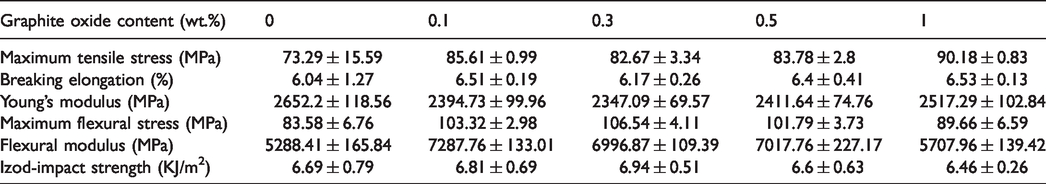
The composites developed in the present research show seven days of water equilibrium time. As shown in Figure 17the water uptake by the composites increases with an increase in fibre volume fraction. However, the amount of water absorbed by the composite decreases with time. The total amount of water absorbed until equilibrium was 0.253, 0.261, 0.372 and 0.532 g for composites with 0.1, 0.2, 0.3 and 0.4 fibre volume fraction, respectively. The equilibrium water uptake by recycled cellulose fibres (40 wt.%) and epoxy composite is 17.14% [7]. Whereas the composites developed in present research with 0.4 fibre volume fraction shows 8.32% equilibrium water uptake. As shown in Figure 18, the slope of the water absorption curve is increasing with an increase in fibre volume fraction owing to increased diffusion of water inside the composite with an increase in fibre volume fraction. As shown in Table 5, the diffusion coefficient decreases with the increment in fibre volume fraction. The diffusion coefficient of developed composite specimens is lower than pine, oak and linden wood [47]. Table 5also shows that the water transmission rate and the absorption coefficient of the composite specimen increase with the increment in fibre volume fraction. This is due to the fact that with an increase in fibre volume fraction, more numbers of surface fibres are available to absorb the water as shown in Figure 19and the fibre-to-fibre contacts within the composite also increase which lead to higher wicking effect. Therefore, the permeability coefficient also increases with the increment in fibre volume fraction.

Water uptake by the composite specimen with different fibre volume fractions.

Water absorption curve of the composites with different fibre volume fractions.
Water uptake characteristics of composites with different fibre volume fractions.
FVF: fibre volume fraction; D: diffusion coefficient; WTR: water transmission rate; M∞: equilibrium water content; θ: the slope of the moisture absorption curve; S: absorption coefficient; P: permeability coefficient.

Edge (a) and surface morphology (b) of a composite specimen with 10% FVF, Edge (c) and surface morphology (d) of a composite specimen with 40% FVF.
Conclusions
The cotton fibres extracted from textile waste can be successfully employed to reinforce the composite materials. The addition of graphite oxide nanoparticles improves the mechanical properties of the composites. The composites developed in the present research show required mechanical properties to be used in items of furniture material and to develop some visible and non-visible automotive components. The storage modulus of composites increases with the increment in fibre volume fraction. The composites developed with and without GO nanoparticles are thermally enough stable. The improvement in even distribution of GO nanoparticles within the composite specimen will further improve the mechanical properties of the composites. The water diffusion coefficient of the developed composites is lower than pine, oak and linden wood. Furthermore, the techno-economic study of the developed composites for proposed applications is required to promote these composites in the market.
Footnotes
Declaration of conflicting interests
The author(s) declared no potential conflicts of interest with respect to the research, authorship, and/or publication of this article.
Funding
The author(s) received no financial support for the research, authorship, and/or publication of this article.
Supplemental material
Supplemental material for this article is available online.