
Abstract
Thermoplastic compression resin transfer moulding coupled with injection moulding is an appealing process for the production of thermoplastic composites. However, its implementation at an industrial scale remains challenging as variotherm injection moulding could prevent solid skin formation in the parting line, making cavity sealing difficult. In this study, a tool for thermoplastic compression resin transfer moulding and the related methods and process parameters for an implementation at an industrial scale are presented. The validity of the concept is proved by producing and characterizing composite plates with elevated fibre volume fractions and advantageous mechanical properties at a range of production temperatures within a cycle time not exceeding 20 min. The best mechanical properties were obtained at a production temperature of 270°C with a bending strength of 477 MPa, a flexural modulus measured at 25.7 GPa and a fibre volume content of 67%.
Keywords
Introduction
Fibre reinforced polymers (FRP) exhibit high stiffness and strength at low weight and are therefore attractive materials for lightweight structures in various applications in the mobility and energy sector. 1 While manufacturing technologies have sufficiently matured for applications in commercial aviation,2,3 their elevated production costs and cycle times prevents their broader application in mass production sectors such as in the automotive industry.4,5 In addition to the weight saving potential of composites, their use also leads to a lower environmental impact as demonstrated by Wegmann et al. for the case study of a composite car hood. 6 A broader implementation of composites in automotive applications however still requires further reductions in production costs, cycle times and improved recyclability.
Historically, thermoset composites are more widespread due to their low matrix viscosities, processing pressures and temperatures. However, an increasing attention is given to thermoplastic composites owing to their higher fracture toughness and their ability to be welded and recycled. 7 Furthermore, thermoplastics are more suitable for automated production at shorter cycle times which makes them better adapted to high volume production. The main challenge with thermoplastics lies in their high melt viscosity which is usually above 200 Pa.s. This is typically 2 or 3 orders of magnitude higher than that of thermosets and makes impregnation a challenging matter. State of the art manufacturing processes of fibre reinforced thermoplastic (FRTP) composites in structural applications are primarily based on semi-finished products, namely organosheets or tapes. By carrying out the impregnation step outside the mould, the shaping process is only limited by the formation of intimate contact 8 and reptation between plies, however these semi-finished products represent an additional step and are rather costly.
Several approaches to apply thermosets manufacturing techniques such as resin transfer moulding (RTM) and compression resin transfer moulding (CRTM) to FRTP production have been reported. One approach is to use reactive thermoplastic resins, implying that monomer polymerization occurs in a mould cavity. In this process, the reinforcing fibres are impregnated with low viscosity monomers before transforming them into a thermoplastic through ring opening polymerisation. This method was applied to polyamide (PA) 9 and more recently to polymethylmethacrylate (PMMA) 10 and polyaryletherketone (PAEK). 11 Some obstacles still have to be overcome however, for instance the high sensitivity of the process to residual moisture content and contaminations in the case of polyamide, which can lead to incomplete polymerisation and makes it difficult to control in an industrial environment. 12
Other approaches are based on novel thermoplastics with a very low melt viscosity that have been introduced to the market over the past few years.
13
Because their viscosity still remains higher than that of conventional thermosets, one option is to combine these with fabrics displaying an increased permeability. Syerko et al. proposed an approach to design dual-scale porosity textiles with enhanced permeability
14
and Salvatori et al.15,16 recently presented at the lab scale a variant of RTM processing in which 3D spacers are used to enhance the flow before collapsing. Another process is thermoplastic compression resin transfer moulding (TP-CRTM), in which the fabric is impregnated in the through-thickness direction to reduce the flow length. This process offers the advantage to achieve impregnation and part net shaping in a single production step. According to Darcy’s law, filling time scales with the square of flow length and linearly with the inverse of viscosity; this approach thus seems very favourable to mitigate the drawback of impregnating with a high viscosity polymer. The idea to use widely available injection moulding machines in TP-CRTM as represented in Figure 1 to impregnate and shape thermoplastic composites is thus compelling, as it would enable large existing industry segments to manufacture lightweight structures. Schematic representation of TP-CRTM with injection moulding. The injection moulding machine melts and injects polymer in the cavity on top of the preform. The mould is then closed such as to force the polymer into the fabric and impregnate the fibres.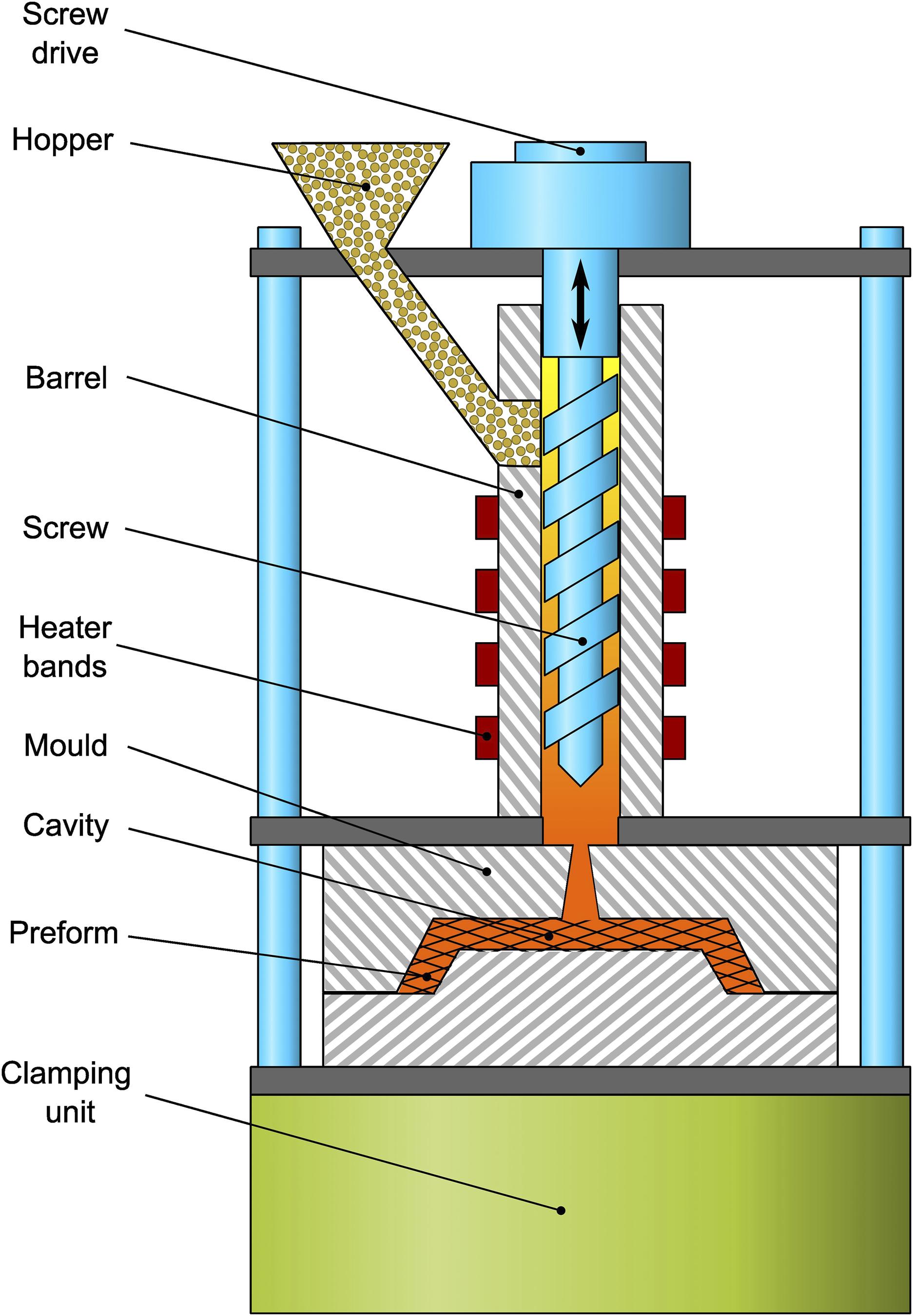
Studer et al. 17 investigated the effects of processing parameters on the through-thickness impregnation of TP-CRTM with press moulding and highlighted the need to consider textile compaction. They demonstrated that the textile architecture and its effect on permeability and compaction behaviour strongly impact the process kinetics. In addition, a higher fibre volume fraction was found to be beneficial for the process as it avoids the presence of a residual pure polymer layer on the injection side of the composite. This unexpected feature is to our knowledge unique, as increased fibre volume fractions are generally associated with more difficult processing. In spite of these compelling advantages, several challenges remain. In an industrial perspective, the repeated variotherm cycling of a mould cavity may cause challenges in dimensional accuracy and thermal stresses. While injection moulds are run at a temperature well below melt temperature and therefore spontaneously seal upon melt contact through skin formation, this is not necessarily the case for a variotherm cavity. This has led to considerable challenges in industrialization attempts.
In this article, a novel variotherm mould developed specifically for TP-CRTM combined with injection moulding is presented. For the first time, a variotherm injection compression mould which can be processed at mould temperatures above 300°C with very low viscosity polymers (<10 Pa.s.) is implemented successfully with a proper sealing through skin formation and methods to identify suitable process parameters are described. The feasibility of TP-CRTM coupled to injection moulding at an industrial scale is demonstrated by producing and characterizing parts displaying an elevated fibre volume fraction and excellent mechanical properties. By presenting guidelines for TP-CRTM with injection moulding, it is sought to fill the gap between the laboratory scale experiments and industrial scale manufacture.
TP-CRTM description
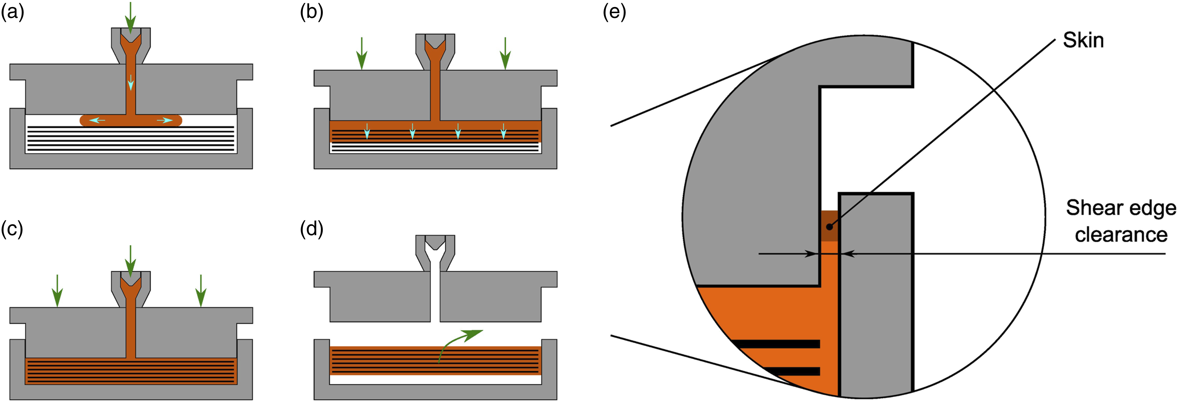
The idea of TP-CRTM with variotherm injection moulding is to directly impregnate the textile in the through-thickness direction with an injection moulding machine into a preheated mould as represented in Figure 2. At the beginning the process the mould is heated up and the textile placed in the cavity. The mould is then closed such as to leave a gap between the textile and the top of the cavity. During the first stage shown in Figure 2(a), the melt is injected in this gap by the injection moulding machine whose screw head is represented at the top. Once the matrix is spread over the surface of the textile, closing tool pressure drives the melt through the textile as shown in Figure 2(b). To obtain a high part quality, the molten thermoplastic needs not only to flow in the through-thickness direction but also needs to properly impregnate the tows and each fibre. In addition, the textile should be given time to relax to obtain homogeneous properties in the through-thickness direction and mitigate inhomogeneous pressure gradients as described by Therzaghi’s relation.
17
At the end of the impregnation process, the cavity is cooled down to solidify the thermoplastic as represented in Figure 2(c), then the mould opens and the composite is ejected as pictured in Figure 2(d). Schematic representation of the direct thermoplastic melt impregnation with variotherm injection moulding process. Figure 2a shows the thermoplastic melt injection followed by the textile impregnation in Figure 2b, then cooling down in Figure 2c and finally part ejection in Figure 2d. Figure 2e shows a close up picture of the shear edge, where solidified thermoplastic in the shear edge clearance forms a skin sealing the tool. Adapted from.
17
TP-CRTM implementation
Mould development
A novel mould was specifically designed to overcome the challenges of TP-CRTM with injection moulding machines and produce parts with a variotherm approach and an active temperature control for sealing skin formation in the shear edge clearance. The apparatus can produce plates with a diameter of 100 mm with a thickness of up to 10 mm. The tool was mounted on an Arburg allrounder 320 A 600–170 injection machine equipped with a stamping function. The tool was built with four different tool steels based on weldability, hardenability and thermal expansion coefficient in a way that maximizes dimensional accuracy. The injection machine was placed horizontally, but a vertical placement is preferential because of easier preform positioning for instance.
Figure 3 represents a schematic cross section of the tool in open position with its main components. The upper part on the diagram will be referred to as the injection side and the bottom side as the ejector side. During the process, the tool closes and the reinforcing textile lies in the cavity between the two heating units. Electrical heating elements placed in the latter allow to rapidly heat up to 300°C in the cavity. The U-shaped heating unit has a cavity depth of 10 mm, which determines the maximal plate thickness that can possibly be produced. Directly on top and respectively bottom are placed the cooling units in which an open circuit allows water with a constant temperature between 12 and 15°C to flow. These swift heating and cooling rates are intended to minimize cycle time, which is of prime importance in a high-volume production perspective. Four sensors type H 1295/5/1.5 × 100 from Hasco placed throughout the tool grant detailed information about the thermal status of both the cavity and the mould. One sensor is placed in the sealing unit while the three remaining are placed in the heating unit on the top, bottom and side. The sprue allows molten polymer to flow from the injection machine into the cavity and the ejector pin allows automated demoulding at the end of a cycle. Insulation plates placed on the top, side and bottom of the tool insulate the tool up to 280°C. Another internal insulation separates the heating and cooling elements from the rest of the tool, and can withstand temperatures of up to 400°C. These not only reduce energy consumption but also enable a more precise and stable temperature control. One lateral side of the tool is not insulated -see Figure 3- because the pipes for the tempering circuit are connected there. Schematic cross section representation of the mould in open position along with the main components.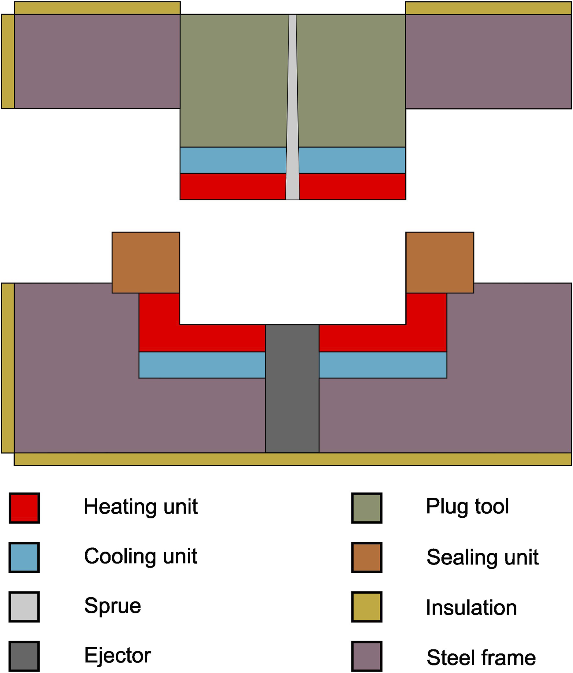
The sealing unit, plug tool and each of the steel parts are all tempered with a closed loop circuit with pressurized water, each independent and controlled individually. The water temperature and flow of each circuit are controlled externally with HB-160Z1 control units from HB Therm and can be tempered up to 160°C except for the sealing unit, which was controlled by a HB-230Z2B that can go up to 230°C. In the thermal management concept that was adopted, the tool is controlled isothermally except for the heating and cooling units whose temperature vary in order to obtain a variotherm cycle in the cavity. This means that the tempered parts of the tool are set to a constant temperature, even during cooling. This approach enables a precise temperature control and sealing management, which is closely related to the tool temperature distribution.
Weldable and hardenable steels were used for the heating units such that the injection side was made harder than the ejector side following standard mould design guidelines and to avoid possible damage caused by the fibres or friction during opening or closing of the tool. The different parts of the tools were designed with tool steels to minimize induced thermal stresses in the final part. 1.4301, 1.2312, 1.2379, 1.2343, 1.1730 and 1.4108 steels following DIN EN ISO 4957 and DIN 17,350 have been used in the design of the mould. Another important aspect in the selection of the steel types was their thermal expansion coefficient which ranges from 12 to 17·10−6 K−1. Because the thermal expansion is not homogeneous in the tool, the size of the shear edge clearance depends on the temperature and temperature differences inside the tool. Since the temperature in the different parts of the tool are regulated individually, the clearance width can be actively controlled. Because sealing of the tools depends on the clearance width and temperature and since both of these can be adjusted, tool sealing is ensured at any time and over a wide range of temperatures. A picture of the tool is shown in Figure 4 where both parts of the tool are displayed. On this picture the heating and cooling zones cannot be distinguished from the plug tool. Pictures of both parts of the tool. On the left: ejector side, on the right: injection side.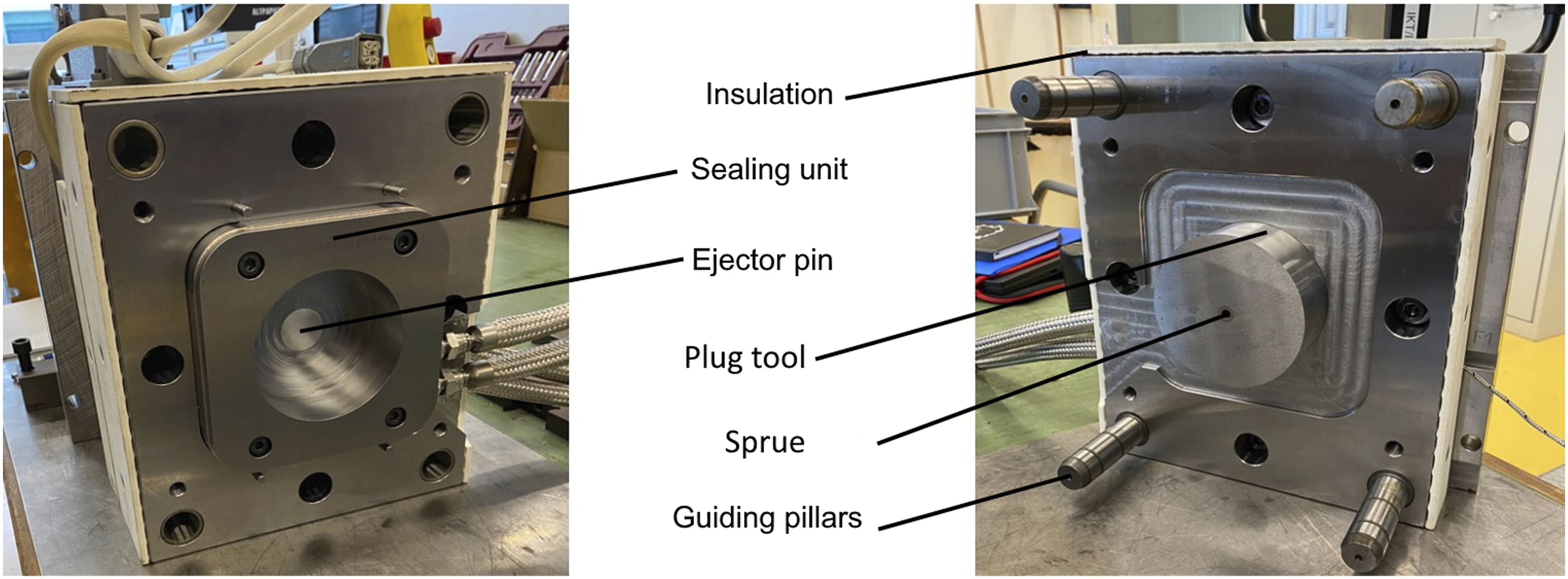
Seal management
Mould sealing is one of the most challenging aspects of the process and is intimately linked to temperature and clearance width management. As the polymer flows in the shear edge clearance it will first flow past the heating unit before reaching the cooling unit and the plug tool. The temperature in this region is significantly lower and the polymer viscosity increases with decreasing temperature until the no-flow temperature (NFT) at which the polymer stops flowing and solid state is reached, effectively sealing the tool as pictured in Figure 2(e). With larger clearance, the flow velocity increases, and the polymer travels a longer distance before solidifying. To ensure adequate sealing, the shear edge clearance must therefore be set small enough such that the polymer will freeze before escaping the tool, which is why clearance width management plays an important role in tool sealing.
Improper temperature and clearance width management can result in a loss of sealing and possibly tool damage in the worst case if insufficient clearance width leads to a collision and jamming. A Finite-Element Method (FEM) thermal analysis of the tool was performed to determine the clearance width. Several uncertainties including dimensional tolerance of the mould parts and model precision need to be considered to avoid tool damage if the gap is too narrow. It was determined that one tenth of a millimetre yielded a satisfactory value to ensure geometrical tolerances and tool sealing.
The clearance width of the tool at room temperature is 0.2 mm. FEM simulation showed that the main factor acting on tool gap during process is the temperature difference ∆T between the heating and sealing unit. Thus, ∆T was calculated to obtain the desired clearance width with given processing conditions. A transient heat simulation in a simplified 2D geometry was developed using COMSOL Multiphysics® as shown in Figure 5 along with the tool temperature distribution for a given cavity temperature of 240°C. This simulation was used to predict if the polymer temperature dropped below the no-flow temperature at some point along the clearance and if skin formation -and thus sealing- occurred. It was assumed that the temperature of the polymer in the shear edge clearance was equal to that of the tool in its immediate surrounding, which is valid because low pressures were applied at the beginning of impregnation and the polymer therefore flows very slowly in the clearance. If the flow speed of the polymer becomes significantly higher as a result of higher pressures or wider clearance, more elaborated simulations should probably be used to determine the temperature of the polymer in the shear edge clearance. Temperature distribution in the tool predicted with the simplified 2D geometry, here for a production temperature of 240°C. The smaller regions represented by circles or oblong-like shapes stand for the heating, cooling and tempering channels.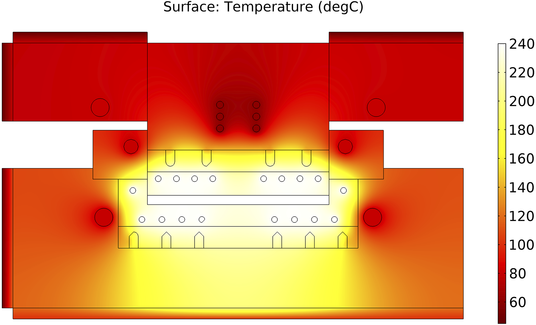
Process parameters
Besides the tempering temperatures in the different zones of the tool, the process parameters are: • • • • • • • •
Operation
The machine was brought into service by producing plates at an increasing range of temperature, to mitigate the risk of polymer leakage in the first experiments and to investigate the influence of temperature for comparison with the results of Studer et al. 17 Regarding impregnation of the textile, higher temperatures are sought because it results in a diminished viscosity and faster matrix flow. On the other hand, higher temperatures require longer times for heating up and too elevated temperatures can cause polymer degradation.
Materials
The low viscosity polymer was thermally stabilised polyamide 6 (PA6) “Evolite® HF XS1480” from Solvay. This material has a melting temperature of 220°C and a density of 1140 kg m−3 according to the technical datasheet. The viscosity in function of the temperature for a shear rate of 10 s−1 was measured with an Anton Paar Physica MCR 300 plate-plate rheometer and is reported in Figure 6. The no-flow temperature (NFT) was estimated to be the same as the temperature of recrystallisation, which is a conservative value since the NFT is usually between the temperature of recrystallisation and the melting point. The temperature of recrystallisation was measured to be 183°C with a DSC 25 from TA Instruments with a heating and cooling rate of 10°C min−1. The polyamide was dried prior usage following the procedure recommended by the manufacturer. Viscosity in function of the shear rate for different temperatures. The dotted line indicates the shear rate of interest for the process: 10 s−1.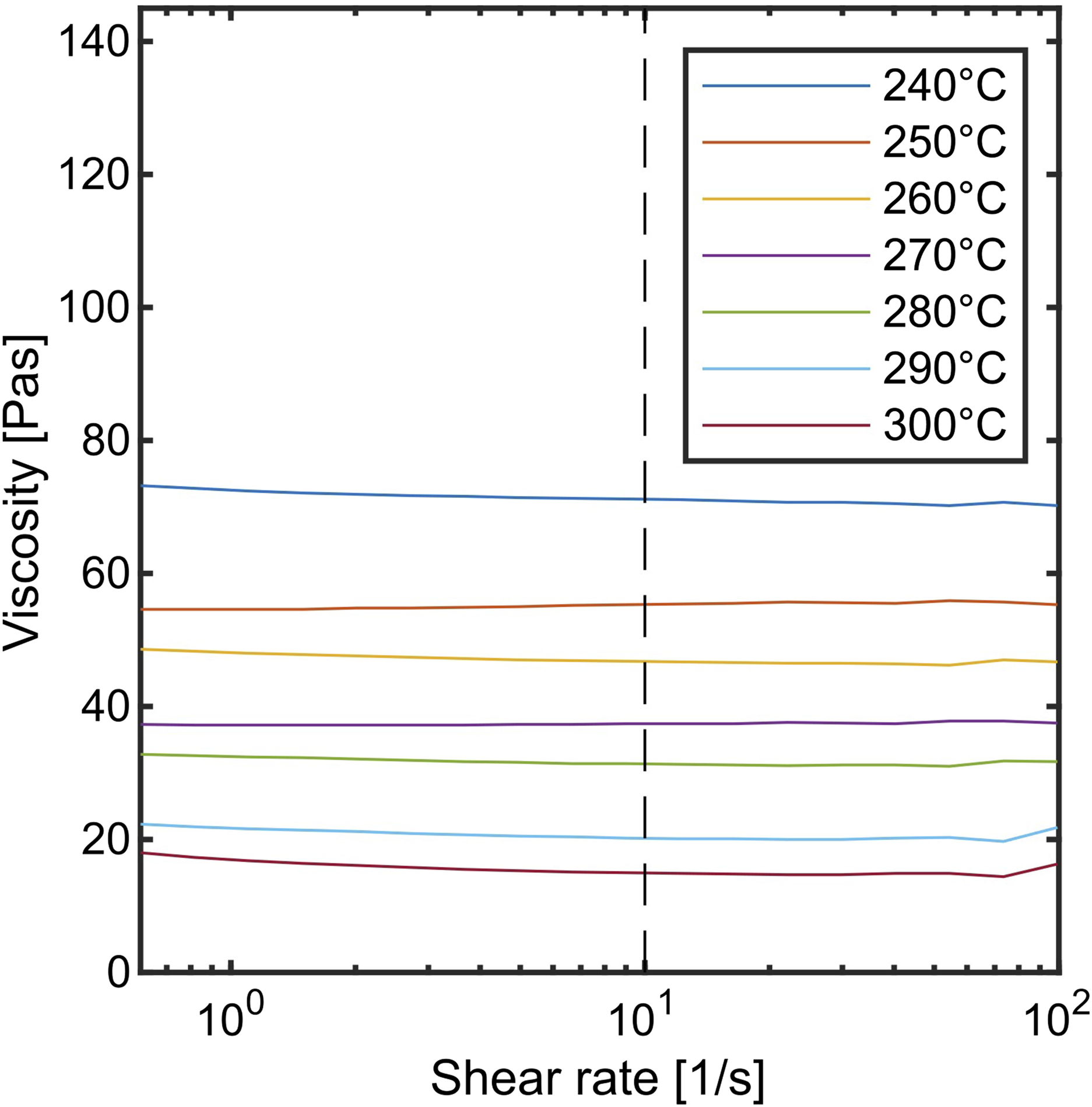
For the reinforcement woven glass fibres with a polyamide compatible sizing was selected. The textile provided by Tissa Glasweberei AG has a plain weave architecture and an areal weight of 600 g m−2 and 1200 tex tows according to the manufacturer specifications. The density of the fabric was measured to be 2620 kg m−3 with the buoyancy method using a precision scale with an immersion set-up and three samples.
Plate production
Plates have been produced at a cavity temperature of 240, 270 and 300°C. Three plates have been fabricated for each temperature to investigate the reproducibility of the process. The plate thickness was set to a value of 2 mm, following the case study where a car bonnet is to be produced with TP-CRTM.
6
Note that since the impregnation time quadratically increases with the part thickness, this latter is of great importance for TP-CRTM. Following the findings of Studer,
17
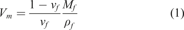
the target fibre volume content was set to 65%. The thickness t of a plate with N layers and a fibre volume fraction of ν
f
for a textile with an areal weight A
w
and density ρ
f
is
List of process parameters and the value to which they have been set in this study.
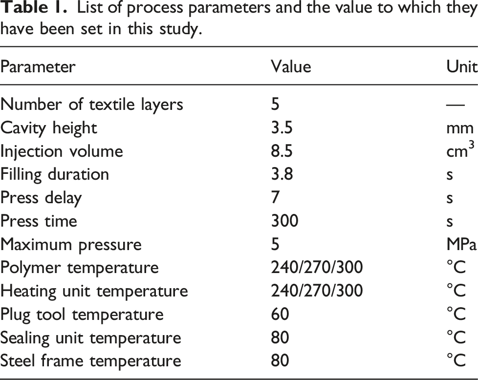
The foreseen number of textile layers were stacked on top of each other with the same orientation and punched with a 100 mm stamp. The punched textile stack was then placed in the mould cavity which was previously coated with the high-temperature, polyamide compatible release agent ACMOS 2–1031-3. The tool was then heated to the production temperature, then the textile was let to rest for an additional minute prior to injection. If the textile is too cold, the molten polymer might solidify in the microscale interstices between the fibres and perturb impregnation. The process was then carried out following the parameters specified in Table 1.
Seal management
The FEM simulations predicted a clearance width between 5·10−2 and 9·10−2 mm for the different production temperatures and the tempering parameters described in Table 1, which are satisfying values. The predicted temperature along the shear edge clearance is shown in Figure 7 for different production temperatures, whereby the x axis is oriented in the flow direction. As temperature increases, the no-flow temperature is reached after longer distances. The variation of the flow distance is yet relatively small with regard to the total clearance length and an elevated margin remains between the point where the no-flow temperature is crossed and the end of the clearance. Figure 7a: Temperature distribution along the clearance and distance at which the NFT is reached for different production temperatures. The clearance length is defined on the basis of the coordinate system represented in Figure 7b, where the reference is placed at the surface of the top heating unit and the axis is oriented towards the flow direction.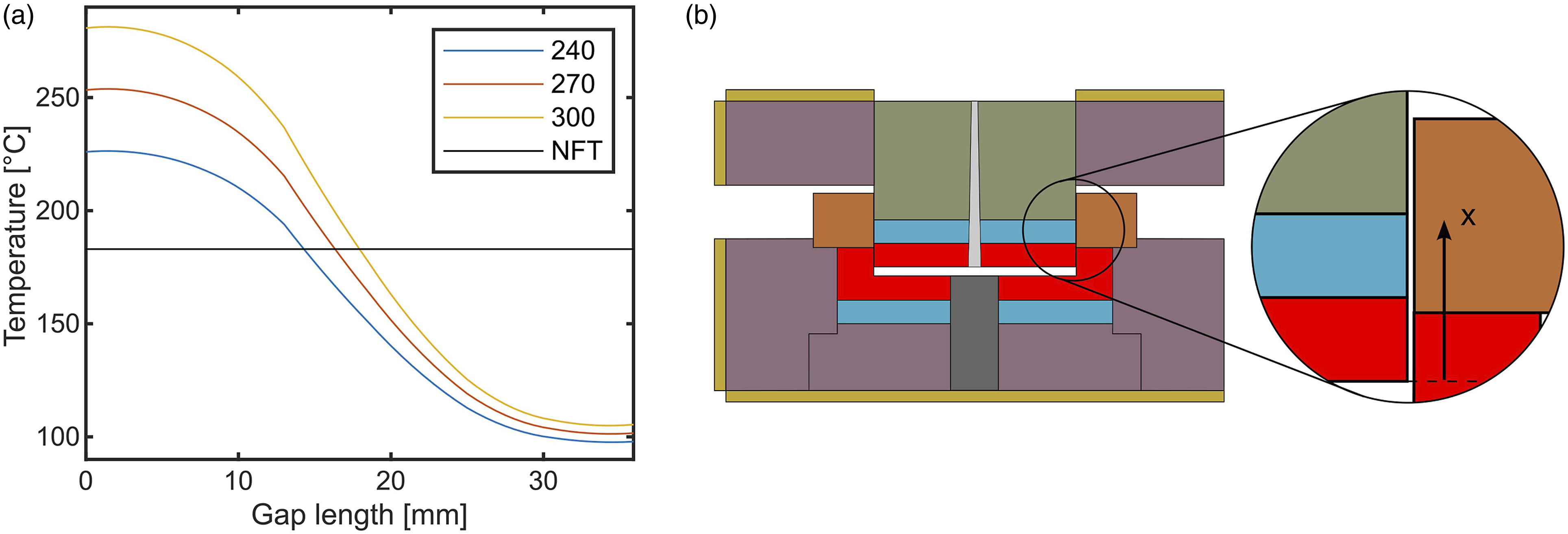
The plug tool plunges less deep in the cavity of thicker parts, resulting in shorter clearance lengths. Therefore, sealing becomes overall more difficult to achieve as the part thickness increases. Another observation is that the achievable temperature difference between the cavity and the end of the clearance is technically limited. Hence, the difference between the melting temperature of a polymer and its NFT is of greater importance than its absolute value.
Plate characterization
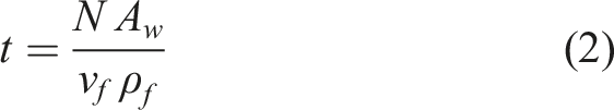
At the end of the manufacturing process, the plates were weighed and their fibre volume content was measured with a gravimetric method. Samples typically in the range of 1.520 g were weighed with a precision scale and placed in a container. The whole was then placed in an oven at 400°C overnight to let the matrix burn off, meaning that at the end of the process only the fibres remain in the container. The textile mass was then weighed and the matrix mass is obtained by deduction. The fibre volume fraction can then be calculated with equation (3) assuming no porosity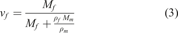
The mechanical performance was investigated by performing a three-point-bending test with a Zwick Roell Z100 universal testing machine and a three-point-bending test apparatus following DIN EN ISO 14,125. For each plate a single rectangular test specimen with a width of 15 mm was cut in the fibre direction with a water-cooled band saw. The test specimen was cut with a minimal distance from the injection point of 5 mm. Finally, parts of the plate were embedded in resin and polished for microscope analysis with a Keyence VKX1100 confocal microscope.
Results and discussion
Breakdown of the cycle time at different production temperatures.
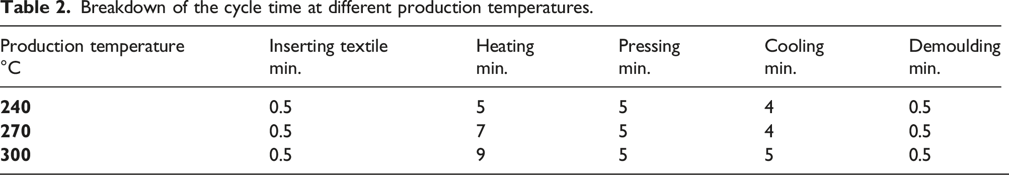
More time is required to heat up and cool down the tool with increasing production temperature, resulting in longer cycle times. During production of a plate at 300°C a ply was misaligned and that sample was discarded, therefore there is only two repeats at that temperature. Visual inspection of the produced plates suggested complete impregnation as the thermoplastic flowed through all the textile layers, for all plates. It also indicated some fibre disorientation near the injection point as it can be seen in Figure 8 but an otherwise undisturbed textile geometry further away from the injection point and on the backside. As fibre disorientation is most likely caused by the injection pressure, gap height and the pressure profile, this should be investigated in future work to propose guidelines to minimize this phenomenon. On the ejector side of the plates, dry spots were observed at lower temperatures as shown in Figure 8(b), however these disappeared at 300°C. Figure 8a: Front side of a plate produced at 240°C. Figure 8b: Back side of a plate produced at 240°C, where dry spots are visible and indicated with arrows.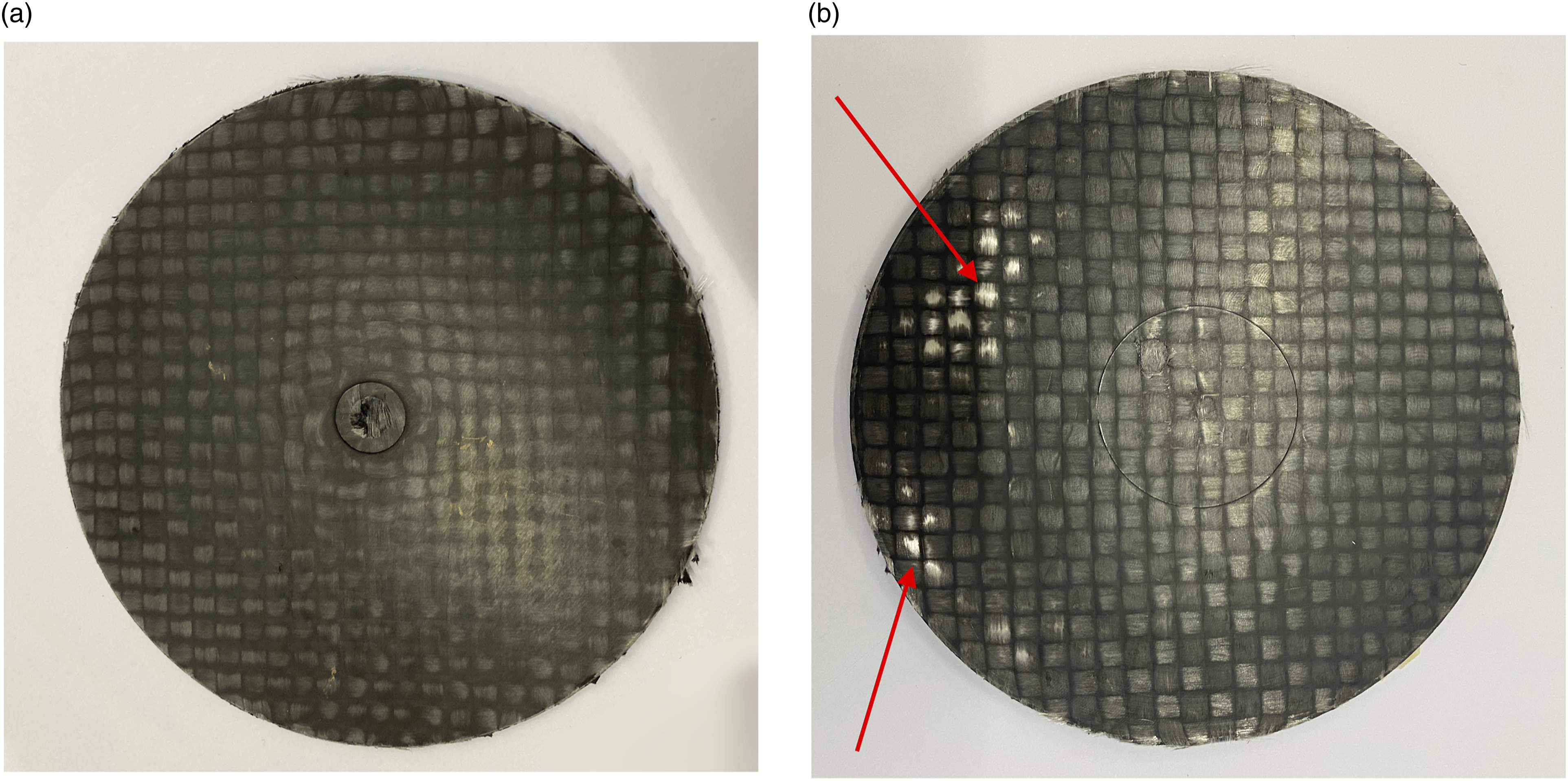
Figure 9 shows a plate produced at 300°C where complete impregnation without dry spots can be observed. The sample presented locally rougher surfaces, which is attributed to thermal degradation. Since the polyamide is thermally stabilized thermal degradation is rather thought to occur in the sizing, which is also polyamide based. In future work care should be taken to select a thermally stabilized sizing, and the thermal stability of the polyamide should be confirmed by experimental investigations. Front side of a plate produced at 300°C. The zone with a rough surface, which is attributed to thermal degradation, is indicated by a red arrow.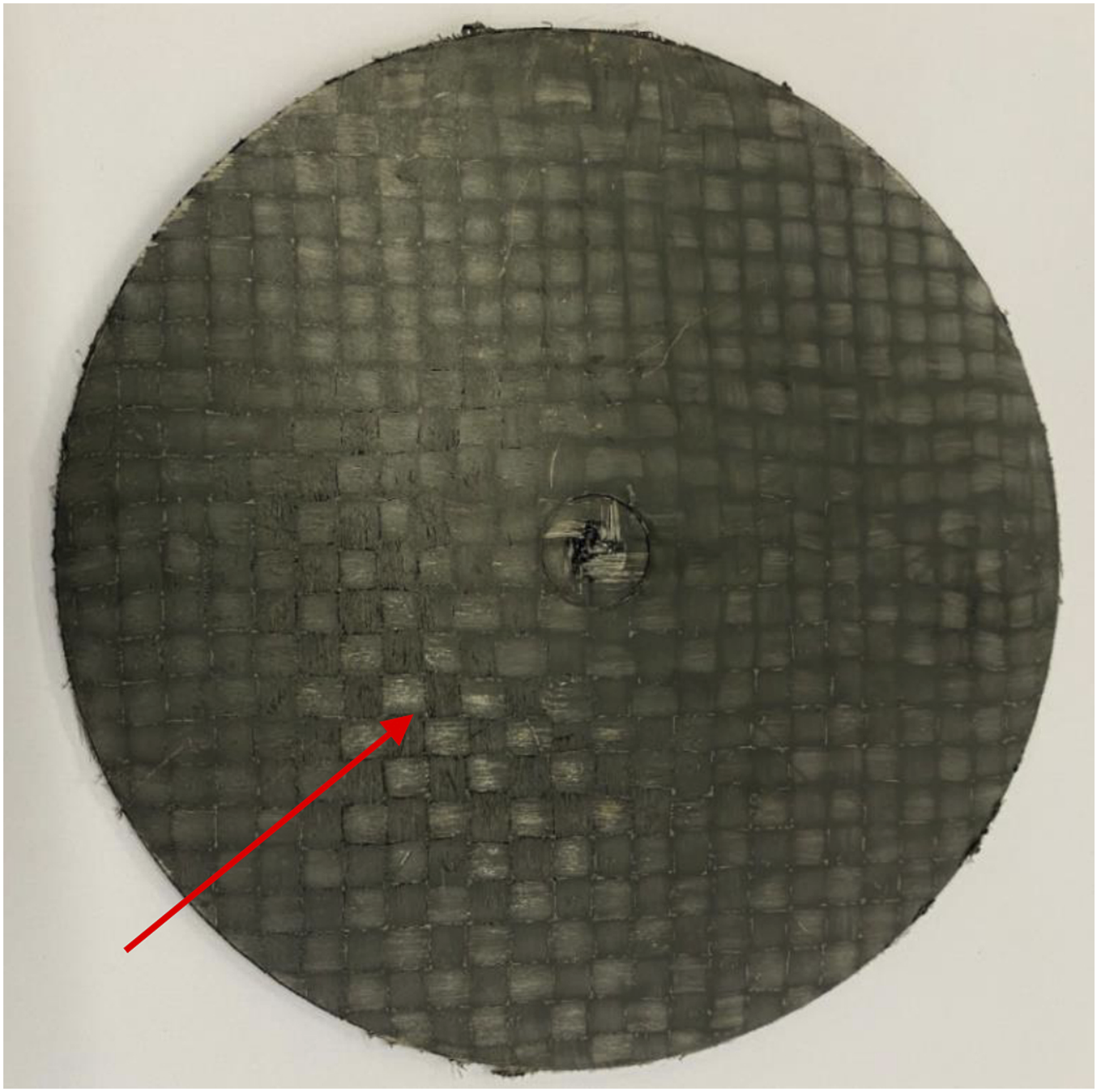
These dry spots are attributed to air which gets entrapped on the ejector side during impregnation as shown in Figure 9(a), where polymer flows and solidifies in the shear edge clearance early during impregnation, effectively sealing it. Since gas diffusion in polymers exponentially depends on temperature, 21 more air is absorbed at higher temperatures explaining why the dry spots disappear. To reduce air entrapment, we recommend an alternative design as presented in Figure 9(b) where the clearance is sealed at the very end of impregnation and allows air to escape during a significant part of the process. However, as the placement of the textile is more difficult since there is no cavity to guide it, imperfect placement of the textile could result in fibre crossing the shear edge and damaging the tool. This problem should be addressed if such a design were to be implemented.
The fibre volume fraction was measured to be 65% at a production temperature of 240°C, which corresponds to the targeted value, and increased to 67% at 270°C and 72% at 300°C. The standard deviation at the different production temperatures did not exceed 3%, which tends to indicate a rather robust process. The plate mean thickness, directly linked to the fibre volume fraction, was measured to be 1.84, 1.77 and 1.64 mm at the production temperatures of 240, 270 and 300°C. The decreasing plate thickness could be explained by several factors: 1. 2. 3.
It is difficult to estimate the magnitude of these three effects but the internal loss is thought to significantly contribute to it while the amount of thermoplastic in the clearance seems to be negligible. We suggest to adjust the injection volume, which is an easy and quick method to fix this problem. Qualitatively little warpage is observed at lower production temperatures with a moderate increase at higher temperatures.
Microstructural analysis
For each plate a micrograph was produced and analysed, representative pictures for each process temperature are shown in Figure 10. The composite displays a complete impregnation of the bundles and overall a very low porosity. However, porosities were locally observed in the regions that are probably the dry spots mentioned earlier, as observed in Figure 10(b). The composite is quite homogeneous and no formation of a layer of pure polymer on the plug tool side is observed as reported by Studer et al.
17
at lower fibre volume fractions. The ply compaction appears to be more constant through the thickness at higher temperatures and fibre volume fractions: at 240°C the plies are slightly less compacted on the plug tool side while at higher temperatures the plate is homogeneous in the through-thickness direction. This is attributed to the lower thermoplastic viscosity at higher temperatures, favouring faster textile relaxation, and to the reduced need for the preform to relax at higher final volume fractions, as is the case with higher temperature processing. Figure 10a: Representation of the tool used in this investigation during impregnation. The shear edge clearance is sealed and air gets entrapped on the backside. Figure 10b: Representation of an alternative tool design during impregnation. The clearance is still open and allows air to escape during most of the process.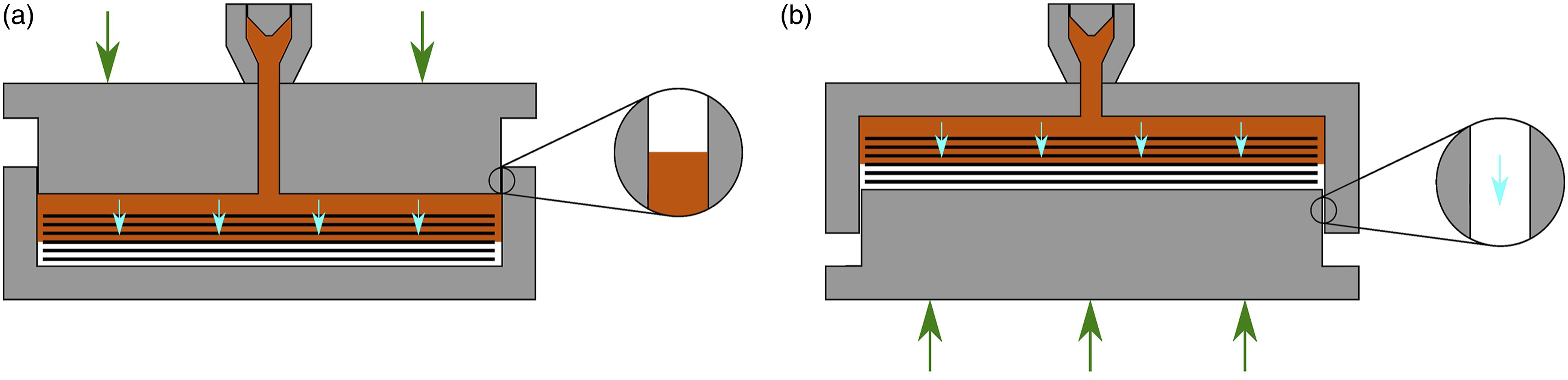
Mechanical characterization
The flexural modulus and strength measured with the three-point bending test are displayed respectively in Figures 11 and 12 reveal overall remarkable mechanical properties. The flexural modulus displays a moderate dependence on production temperature, the flexural modulus is 14% higher at 270 than at 240°C. The highest flexural strength was measured to be 477 MPa at 270°C and at that production temperature the flexural modulus was measured at 25.7 GPa. For comparison, an E-glass/ PA6 organosheet with a 2/2 twill architecture and a fibre volume content of 47% from Lanxess
22
tested with the same method had a flexural modulus and strength of 20 GPa and 580 MPa. Significant differences of up to 40% in strength are observed depending on the process parameters. Cross sections of plates produced at: 11a) 240°C, 11b) 270°C and 11c) 300°C. The injection side is on top and the porosities in Figure 11b) are indicated by red arrows. Flexural modulus of the samples produced at different production temperatures.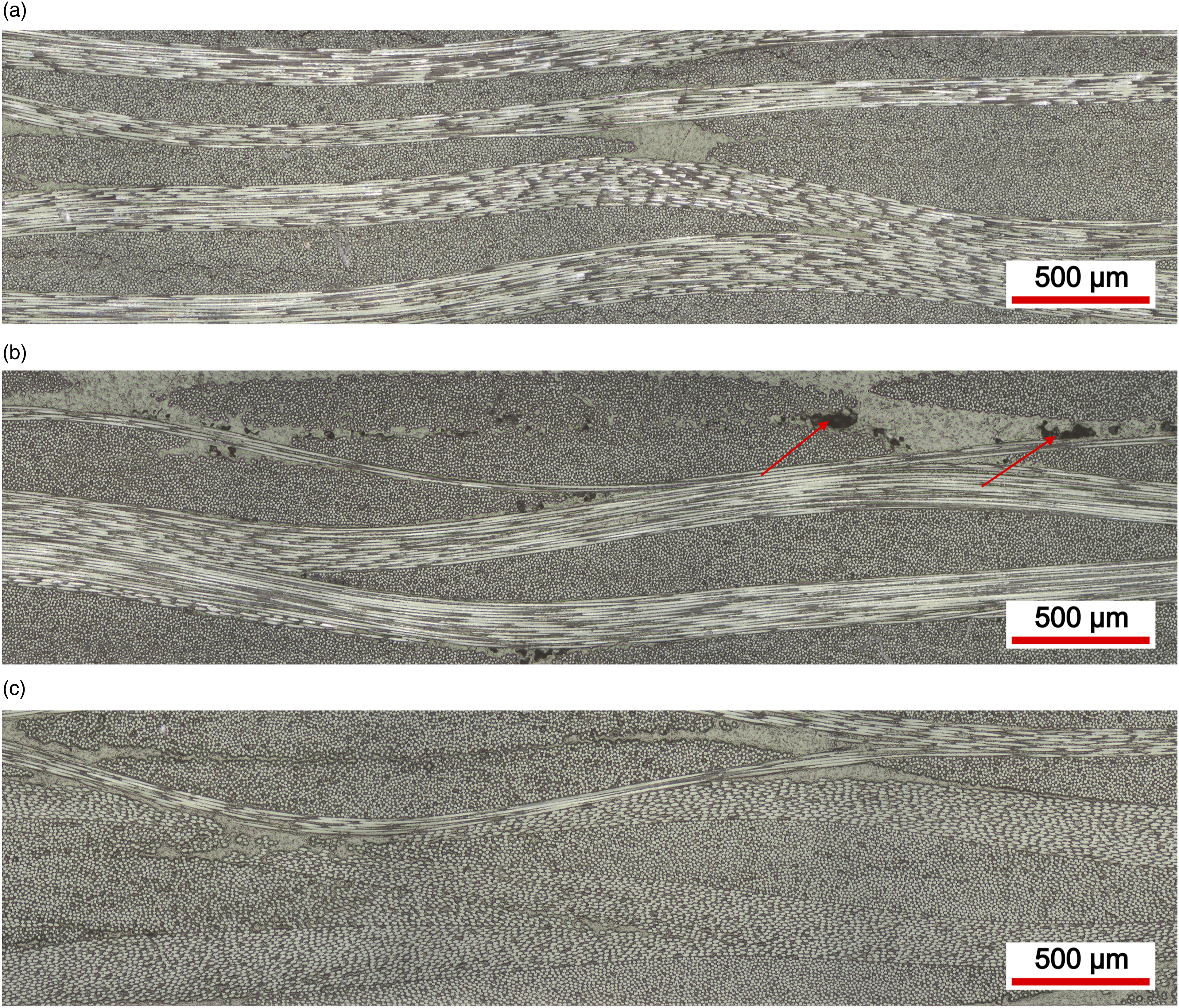
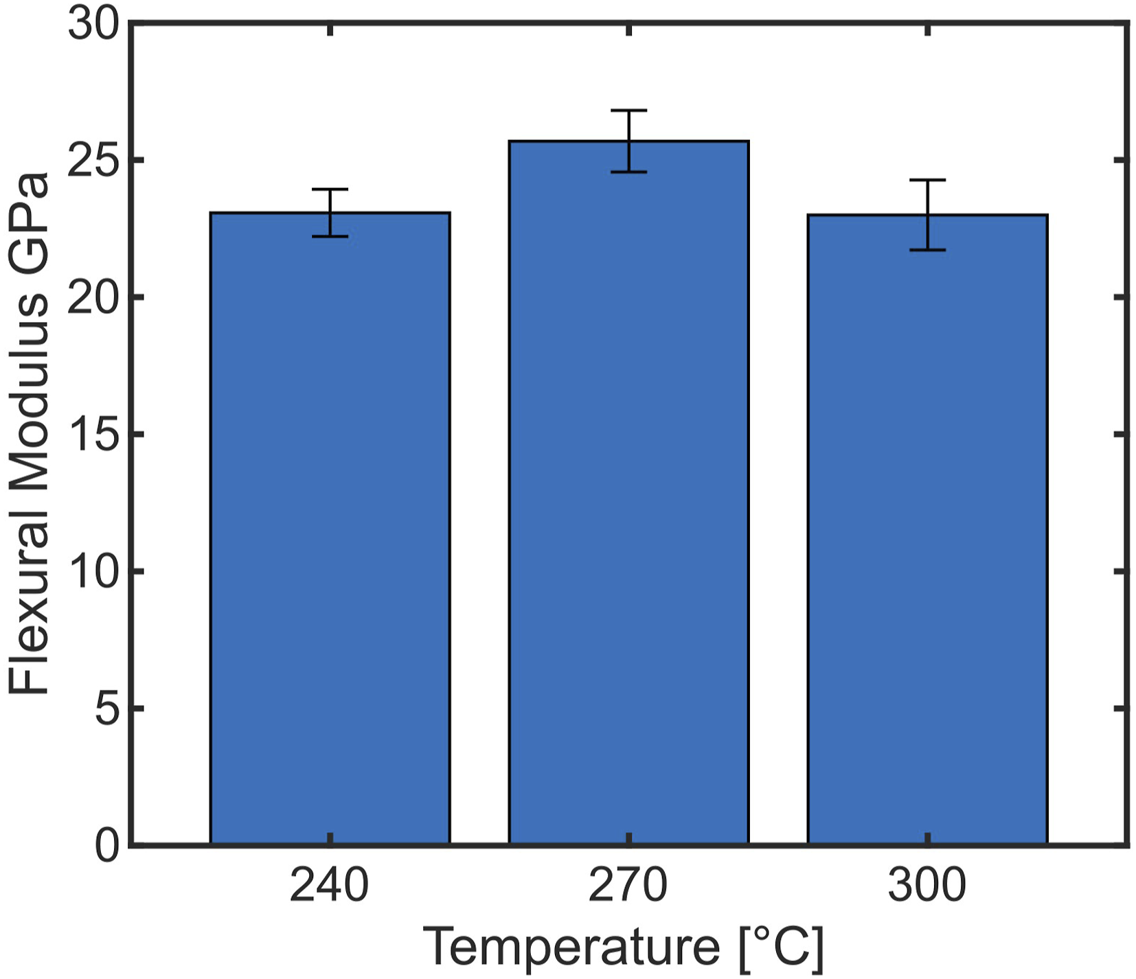
Figure 13 shows the stress strain curves of the samples measured during the three-point test bending. The samples do not fail abruptly but lose gradually strength before final failure, which is typical of delamination. The strain at ultimate strength varies between 1.55 and 2.38 depending on the production temperature, whereas the highest mean strain was measured at 270°C Figure 14. Stress strain curves of the samples produced at different production temperatures.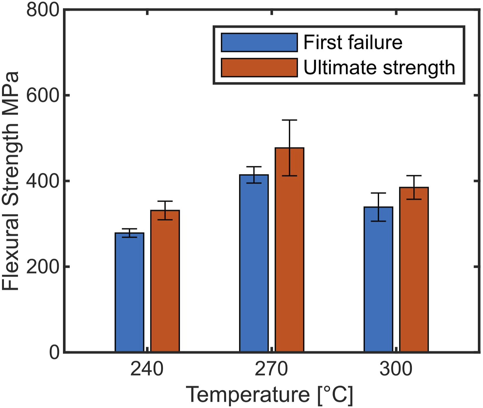
An increasing fibre volume fraction was measured with increasing processing temperature, which should have a positive impact on the composite strength and stiffness. However, the magnitude of the change in mechanical properties as well as the loss of properties when raising the production temperature from 240 to 270°C are not thought to be attributed to changes of fibre volume fraction only and therefore indicates that other phenomena may take place. An increasing fibre volume fraction implies that more stress must be applied to further compact the plies. At very elevated fibre volume fractions, this can lead to the breakage of individual fibres. As textile stress response displays an exponential dependence on fibre volume fraction,
23
a slight increase in fibre volume fraction can lead to significantly higher stresses in the textile and therefore increase potential fibre damage. Fibre breakage could thus contribute to the loss of flexural strength at 300°C. Another effect which could explain this behaviour is the likely thermal degradation of the sizing at that temperature. Flexural strength at first failure and ultimate flexural strength of the samples produced at different production temperatures.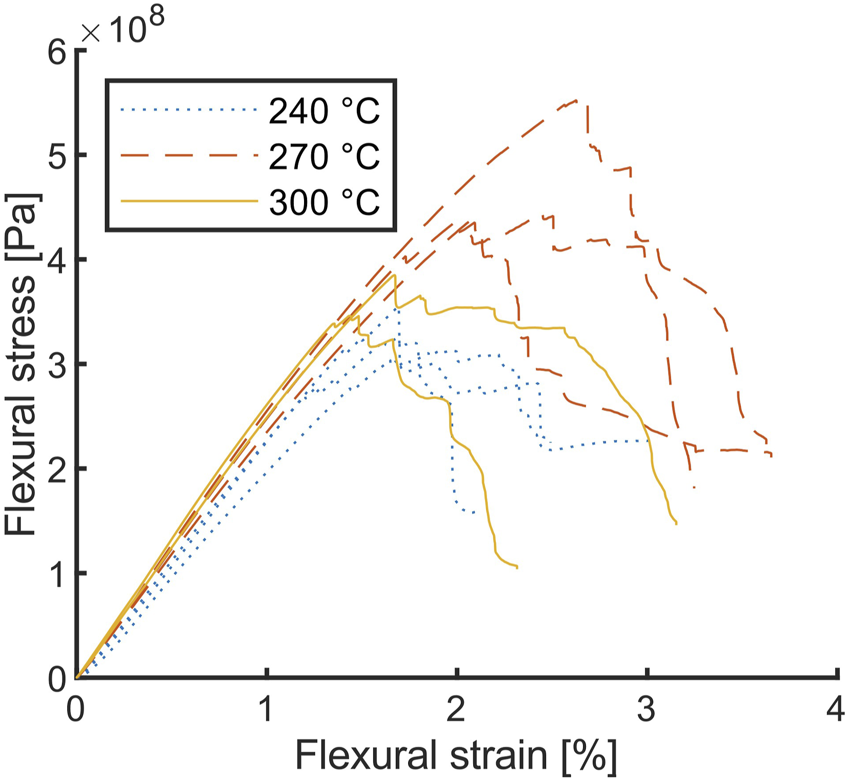
Another factor influencing the mechanical properties is the meso structure of the composite. The composite is more homogeneous through the thickness at higher temperatures. This is desirable to reduce warpage during production, and potentially reduces interlaminar stresses in the part. Voids can significantly decrease the mechanical properties, 24 even if they only arise locally. The disappearance of dry spots at high temperatures corresponds to increased diffusion into the polymer and therefore better mechanical properties.
From a process point of view, adequate selection of process parameters results in high quality parts even at lower temperatures than previously identified by Studer, 17 which not only decreases the costs as less energy is required but also contributes to reducing the cycle time since heating up and cooling down is faster.
Conclusion
A novel tool for thermoplastic compression resin transfer moulding combined with injection moulding is presented. Methods to define robust process parameters ensuring that the tool remains sealed throughout the variotherm cycle are described. The process was successfully implemented with glass textile and PA6 to produce plates at different temperatures up to 300°C while keeping the cycle time under 20 min, which was however not optimized and could be significantly reduced in future work.
The composite has a very high fibre volume fraction and the best set of process parameters results in mechanical properties comparable to organosheets based on similar materials. 22 The feasibility of the process in an industrial environment and the relevance of TP-CRTM for the manufacture of fibre-reinforced thermoplastics are demonstrated. The process parameters presented in this work were defined overall conservatively, some of them could be determined more accurately in future work. For example, then no-flow temperature could be determined with flow index testing.
The results presented here are in agreement with previous studies as fully consolidated plates could be produced in the previously identified process window. Targeting an elevated fibre volume fraction avoided the formation of a pure polymer layer or inhomogeneities in the through-thickness direction, as observed by Studer et al. 17 It was possible to obtain a fully consolidated composite at lower production temperatures for the same impregnation time as previously identified, which is probably due to the use of a different textile. This result highlights the importance of the textile and textile architecture for the process.
Being able to produce composite with a given impregnation time at lower temperatures is beneficial for the process, as a lower production temperature reduces the time required for heating and cooling, as well as the costs since less energy is required. Alternatively, the impregnation time can be reduced instead, which also reduces the cycle time. The optimal balance between reduced heating/cooling time and impregnation time remains to be found and should be investigated.
In conclusion, it is demonstrated that TP-CRTM combined with injection moulding is feasible in an industrial perspective and the gap between research and industrial manufacture was reduced. The process was found to be reproducible in terms of fibre volume content and mechanical properties. The aspects that should be investigated in future research to further optimize the process have been identified.
Footnotes
Declaration of conflicting interests
The author(s) declared no potential conflicts of interest with respect to the research, authorship, and/or publication of this article.
Funding
The author(s) disclosed receipt of the following financial support for the research, authorship, and/or publication of this article: This project was funded by SCCER (Swiss Competence Center for Energy Research) 15916.1 PKOEN; Efficient Technologies and Systems for Mobility, 2013–2020. We kindly thank Mr Schneeberger and Tissa Glassweberei AG for providing the textiles and for their precious support. We also would like to thank Mariona Diaz for her help during the project.