
Abstract
The main purpose of this work is to make lightweight carbon/carbon fiber composite with low density and low thermal conductivity for high-temperature furnace. Lightweight carbon/carbon fiber composite thermal field insulation materials were prepared by the process method of needle punching—molding curing high-temperature graphitization. The results show that the long carbon fiber in the carbon/carbon fiber composite forms a three-dimensional structure of X-Y-Z with a density of 0.16 ± 0.02 g/cm3, which makes the composite material have excellent thermal insulation performance at high temperature. The thermal conductivity of the carbon/carbon fiber composite at 2000°C is only 0.38 W/(m·K), and the impurity element content is only 19.09 ppm. The method of needle-punching-forming-felt high-temperature graphitization can provide some suggestions for the preparation of the lightweight long carbon fiber composite.
Keywords
Introduction
Carbon fiber has excellent high temperature resistance, especially in the high-temperature environment above 1500°C, under the protection of inert gas.1,2 Materials such as steel, silicates, and most alloys have been melted, while carbon fiber materials maintain excellent thermal field performance without compromising the overall performance. For example, the growth of solar silicon crystals needs a high temperature of 1500°C or higher, and many high-temperature crystal treatments also need above 1500°C. The high temperature resistance of carbon fiber and the insulation requirements of the growth of high-temperature crystals have led to the application of carbon fiber insulation materials in high-temperature insulation environments, namely carbon/carbon fiber composites. Carbon/carbon fiber composite materials include low-density carbon/carbon insulation materials (0.1–0.4 g/cm3)3,4 and high-density carbon/carbon materials (1.0–1.8 g/cm3).5,6 This article focuses on low-density, lightweight carbon/carbon fiber composite insulation materials. Lightweight carbon/carbon fiber composite insulation materials are widely used in solar polysilicon furnace, single crystal silicon furnace, semiconductor furnace, sapphire furnace, fiber drawing furnace, high-end metallurgical heat treatment furnaces, as well as in other high-temperature insulation environments.7–12 These are all due to the excellent high temperature resistance, high-temperature insulation performance, and low impurity element content of the carbon/carbon fiber composite.
At present, lightweight carbon/carbon fiber composites are mainly divided into two categories13–15 according to the length of the fibers: (a) short-cut (fiber lengths in millimeters, such as 3–5 mm) and (b) long-cut (fiber lengths in centimeters, such as 10–15 cm) carbon/carbon fiber composites. Short-cut carbon/carbon fiber composites are mainly represented by SGL Group (Germany) and Morgan Corporation (USA). When the lightweight carbon/carbon fiber composite thermal field material is impregnated, the chopped carbon fiber and the phenolic resin are first prepared into a paste and then filled into a mold for solidification molding. The advantage of this molding method is that the step of needle punching can be omitted, and rapid molding is relatively easy in the impregnating resin stage. But one disadvantage is that the chopped fibers in the formed thermal field material are homogeneous and heat can be thermally conducted along the fiber direction, so the thermal field insulation performance is not good. 13 The long-cut carbon/carbon fiber composite thermal field insulation material is represented by a product of Kureha Chemical (Japan). Compared with the short-cut thermal field insulation material, there is an X-Y-Z three-dimensional structure in the felt structure. The carbon fiber felt adopts air-laid needle-punching-forming-felt technology in the preparation process, so the long-fiber arrangement becomes an X-Y plane structure and X-Y plane structure only exists in the stage of air flow forming network. Through the needle-punching technique, there is a small amount of carbon fiber in the Z-direction perpendicular to the X-Y plane, thereby forming an X-Y-Z network structure. The carbon fiber in the Z-direction is interspersed in the X-Y plane network, so that the long carbon fiber felt becomes a three-dimensional felt structure having a mechanical structure, thereby ensuring that it is not easily spread by itself. Since the proportion of fibers in the Z-direction is very low, the heat loss along the Z-direction is small under the thermal field heat preservation condition, thereby ensuring that the insulation performance of the overall felt is superior to the short-cut heat field insulation material.
At present, researchers mainly focus on the short-cut carbon/carbon composite insulation materials; 13 there are few studies on large-scale high-temperature-resistant carbon/carbon fiber composite thermal field insulation materials; and there are certain technical barriers to the long-fiber felting technology. Our team has cooperated with Hangzhou Vulcan New Materials Technology Co., Ltd to overcome a series of process problems and innovatively developed a set of forming processes for preparing lightweight high-temperature-resistant carbon/carbon fiber composite, namely needle punching—molding curing high-temperature graphitization. The innovation is that (a) the carbon fiber used is 100–150 mm long, and the thermal insulation performance of the product is better than that of the short carbon fiber; (b) the direct use of carbon-fiber-air-laid needle-punching-forming-felt process instead of pre-oxygen fiber-air-laid needle-punching carbonization process reduces process steps and avoids product shrinkage due to carbonization. In addition to introducing the preparation process of carbon/carbon fiber composite, the performance of carbon/carbon fiber composite is characterized. It is expected to provide some advice for the application of high-temperature equipment such as crystal growth and high-temperature heat treatment.
Experiment
Materials
The following materials were used in the experiment: carbon fiber (SYT45, 12K; Zhongfu Shenying Carbon Fiber Co., Ltd), absolute ethanol (AR; Sinopharm Chemical Reagent Co., Ltd), and phenolic resin (PF-5408, viscosity = 450–750 (25°C, cP), solid content = 65%, free phenol = 9.5%–11.8%, moisture = 2.5%–4.0%; Jinan Shengquan Group Co., Ltd).
Sample preparation
Schematic diagram of the preparation process of carbon/carbon fiber composite thermal field insulation material in this project is shown in Figure 1. The process is mainly simplified into three steps: (a) soft felting, (b) forming, and (c) graphitization, which will be explained separately.

Schematic diagram of the preparation process of carbon/carbon fiber composite thermal field insulation material.
Soft felting
Soft felt is the determinant of thermal insulation performance in carbon/carbon fiber composites, so the preparation of soft felt is one of its core technologies. The soft felting of this project includes carbon fiber filament cutting, air laying, and acupuncture into felt. The length and type of the fiber directly affect the thermal insulation properties of the prepared carbon/carbon fiber composite. In this article, the length and types of fibers are not considered for the time being. The sample mainly includes the following key steps in the preparation process: (a) carbon fiber filaments (100–150 mm) are directly used as the felt raw materials, avoiding the occurrence of high-temperature shrinkage phenomenon, that is, the shrinkage phenomenon of the pre-oxygen fiber as a raw material in the high-temperature carbonization process does not occur; (b) in the felting process, the fiber alignment anisotropy X-Y plane to Z-direction fiber fraction ratio is (50–250):1, and the felt body weight is 500–900 g/m2, the felt thickness is 10 mm, and the felt width is >1500 mm. The density a of the Z-direction fibers is controlled by the density of the needle plate, thus ensuring that the density of the Z-direction fibers is uniform and maintained at a lower quantity. The heat is easily transferred along the axial direction of the fiber, and the anisotropy can ensure less heat transfer in the Z-direction, thereby ensuring superior thermal insulation properties of the carbon/carbon fiber composite.
Forming
The soft felt needs to be cut into a certain shape, and then the resin is solidified before it can form a certain shape. This project will use the phenolic-resin-impregnated soft felt drying curing process to complete the molding process: (a) for impregnating phenolic resin material, the carbon fiber felt is impregnated with phenolic resin solution. In order to ensure that the viscosity of the phenolic resin is moderate, to fully impregnate the carbon fiber, the phenolic solution and ethanol are mixed to form a phenolic ethanol solution, and the solid content of the phenolic solution is controlled to 30%–40%. The mass ratio of carbon fiber felt to phenolic resin is 1:(1–1.5). The liquid impregnating agent calculated by the ratio is immersed in the blank material at room temperature, and the spray immersion must be uniform; (b) for drying, the impregnated carbon fiber felt is placed in a vacuum apparatus by means of a negative pressure, and the ethanol is absorbed and recovered, and the ethanol content is controlled to be 5% or less. The dried sample is hung on a wire mesh stand for storage at a temperature below 30°C; (c) for molding and pressing curing, the release paper is pasted in the mold, and the impregnated green material is neatly loaded into the mold, and then the mold is placed in a 30-t press for one-time forming pressing. The sample is pressure-cured, the curing temperature is raised from room temperature to 175°C, and the curing time is 3–6 h. It is recommended to raise from normal temperature to 175°C at 50°C per hour, then cool to below 50°C, and remove from the press. The plate sample can reach 1500 mm × 1500 mm.
Graphitization
Compared with the traditional products, this project directly eliminates the carbonization process of the pre-oxygen felt, so the shrinkage of the product is significantly reduced. The cured sample only needs to carbonize and graphitize the phenolic resin. Care must be taken during this process to control the thickness of the cured plate sample with a platen. The high-temperature sintering process is followed. The solidified intermediate sample is charged into a high-temperature sintering furnace, and each intermediate product is controlled by a high-density carbon/carbon material. At a pressure of 10–8000 Pa, the temperature is raised from room temperature to 400°C at 75°C per hour. Then, the temperature is raised from 400°C to 500°C at 25°C per hour, and the temperature is kept at 500°C for 2 h. Then, the temperature is raised to 2400°C at a heating rate of 25°C to 100°C per hour. The temperature is kept at 2400°C for 1 h, and the composite is purified at the high temperature. It is naturally cooled to room temperature and then discharged. Finally, the carbon/carbon composite insulation material with low metal impurity content is prepared. The prepared sample size can reach 1500 mm × 1500 mm, and the thickness can be made to 40, 45, or 50 mm as needed.
Characterization
The internal microscopic morphology of the carbon/carbon fiber composite was characterized by scanning electron microscopy (SEM; S-2150; Hitachi Corp., Japan). The SEM image includes scanning in both directions: parallel to the plane direction and perpendicular to the plane direction.
The content of each element in the material was determined using an American thermoelectric company’s inductively coupled plasma emission spectrometer (Iris Advantage 1000, Thermo Fisher Scientific). For more details, refer to national standard GB/T 18932.11-2002 (Inductively coupled plasma atomic emission spectrometry (ICP-AES) method).
The thermal conductivity (1000°C–2000°C) under various high-temperature conditions was measured by a heat flow meter method. Schematic diagram of the thermal conductivity test device is shown in Figure 2.

Schematic diagram of the thermal conductivity test device.
The high-temperature thermal conductivity testing system based on heat flow meter is a standard steady-state system according to ISO standard 8301-1991 (Thermal insulation—determination of steady-state thermal resistance and related properties—heat flow meter apparatus). When the hot and cold surfaces above and below the tested specimen are at constant temperature, a unidirectional steady heat flow similar to that existing in an infinite plate will be established in the central region of the specimen under test and in the central region of the heat flow measuring device. The equivalent thermal conductivity of the tested sample was obtained by measuring the heat flux, the temperature of hot and cold surfaces, and the thickness of the sample.
The thermal conductivity calculation formula is shown as follows

where λ (W/(m·K)) represents the thermal conductivity, q (W/m2) represents the heat flux measured by a heat flow meter, and d (m) is the thickness of the sample. T1 (K) is the hot layer temperature measured by an optical pyrometer, and T2 (K) is the cold layer temperature measured by a heat flow meter. The sample measured in this article has a thickness of 50 mm, density of 0.16 g/cm3, and measurement temperature range of 1000°C–2000°C.
Results and discussions
Characterization of carbon/carbon fiber composites
Figure 3 shows the soft carbon fiber felt. As can be seen from Figure 3(b), the carbon fiber soft felt can be made 50 m long. If the long-cut carbon fiber material is abundantly supplied and it can be wound up to infinite thickness, the carbon fiber felt can be made infinitely long and the width can reach 1500 mm or more. Looking closely at Figure 3(a), it can be found that there are many pinholes in the red circles in the position where the felt is rolled up. The presence of these pinholes ensures that the felt body is formed as a whole without loosening, that is, the needle-punched Z-direction fibers are formed on the felt body (X-Y surface). Finally, an X-Y-Z three-dimensional structure is formed, wherein the ratio of the fiber anisotropy X-Y plane to the Z-direction fiber fraction is (50–250):1. Its microstructure will be revealed in the SEM image described below.

Soft carbon fiber felt: (a) roll material; (b) unrolled roll material.
Figure 4 shows the hard carbon fiber felt (lightweight carbon/carbon fiber composite thermal field insulation material). It can be seen from Figure 4(a) that the hard carbon fiber felt sheet can be made to 1500 mm × 1500 mm, and the sheet surface is flat. This can achieve seamless in-panel insulation during the preparation of large-scale thermal insulation material and improve the heat preservation effect. It can be seen from the profiled part in Figure 4(b) that the long-fiber heat-insulating thermal field material can be used not only as a plate but also as a profiled part, and the size of the profiled part can be very precise. The surface of the profiled part can also be specially coated, such as graphite coating, silicon carbide coating, Hf-based anti-oxidation coating, and other coatings.16–24
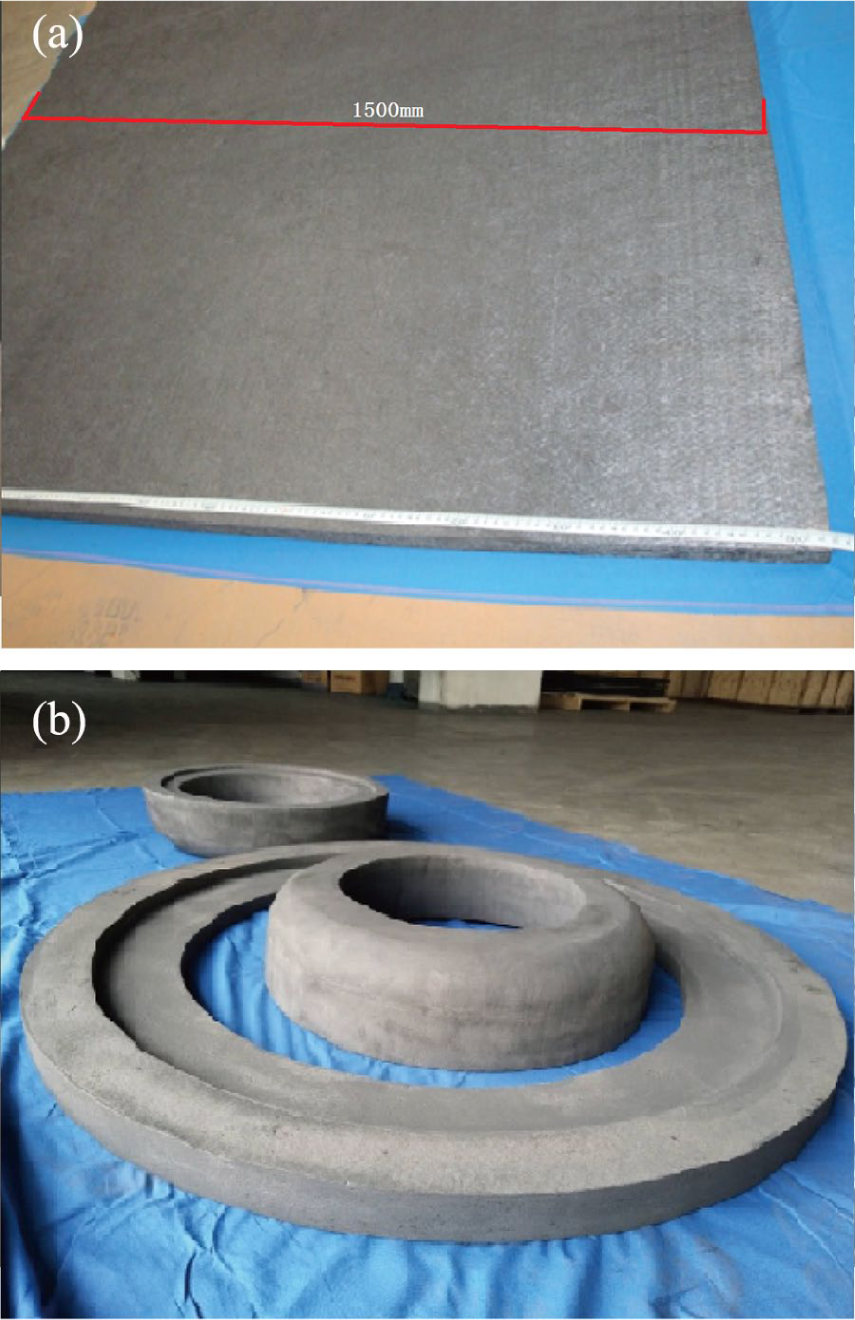
Hard carbon fiber felt: (a) plate material; (b) shaped material.
The density of the carbon/carbon fiber composite prepared by the solidification–graphitization of the reticular composite felt is 0.16 ± 0.02 g/cm3, which is far lower than that of the high-density carbon/carbon composite insulation material (0.3 g/cm3). This low-density network felt structure gives the material superior thermal insulation properties, which will be described in detail below.
Microstructure characterization and thermal conductivity analysis of carbon/carbon fiber composites
Figure 5 shows the microtopography of hard carbon fiber felt, that is, SEM images. Figure 5(a) shows the microscopic topography of hard felt inner surface when it is parallel to the laminate, and Figure 5(b) shows the microscopic topography of the hard felt section when it is vertical to the laminate. It can be seen from Figure 5(a) that the carbon fibers overlap in disorder, and some overlap positions are stuck. The adhesion position is due to the carbon material remaining after the carbonized graphitization of the impregnated phenolic resin, so that the felt material can be strengthened. The strength of the felt body is not easily dissipated and is not easily deformed. As is apparent from Figure 5(b), the carbon fibers are alternately arranged in layers, which is the result of uniform deposition of the carbon fiber felt in layers during the air-laid process in the preparation process. It can also be seen that each layer of carbon fiber is interlaced, but each layer is almost perpendicular to the cross section and there is no carbon fiber parallel to the cross section. The carbon fiber is very tightly packed, and the gap is relatively small, which can prevent the phenomenon of heat convection. This forms a very good thermal insulation structure.

Microtopography of hard carbon fiber felt: (a) hard felt inner surface (parallel to the laminate); (b) hard felt section (vertical to the laminate).
Figure 6 depicts the heat transfer model in a carbon/carbon fiber composite. Heat transfer includes heat convection, heat radiation, and heat transfer.25–27 It can be seen from Figure 5(b) that since the carbon fibers are very tightly packed and the voids are relatively small, the heat convection phenomenon can be prevented. As can be seen from Figure 5(a), the pore size between the fibers is the size of several fibers. The diameter of the fiber is about 7 µm. Even if there is a gap, the heat convection needs to be convected through a tortuous long transmission route. Heat convection transmits less heat in the carbon/carbon fiber composite. The distance of heat convection is much higher than that of thermal radiation. Thermal radiation transfers heat in the form of electromagnetic waves, which transfer heat at a much higher rate than heat transfer through heat convection.

Heat transfer model in carbon/carbon fiber composite.
As for the heat conduction phenomenon, it can be seen from Figure 5(b) that each layer of the carbon fiber is almost perpendicular to the cross section. Heat is thermally conducted in the carbon fiber of each layer. So heat is almost always conducted inside the fiber and in the fiber axial direction. There is only a partial contact point between the fiber layer and the layer at the position where the layer contacts, that is, between the fibers. Even between these contact points, electron or phonon vibration can be carried out, and the path to be experienced is very long, so the heat transferred by heat conduction is also very less. The above description is shown in Figure 6. The heat conduction path is relatively tortuous. Most carbon fibers are perpendicular to the direction of heat flow, and there are very few carbon fibers parallel to the direction of heat flow. Heat transfer is difficult to pass directly through the carbon fiber felt.
It can be seen from the above analysis that the heat transfer by heat convection and heat conduction is very less; the main ways of heat transfer is heat radiation and heat transfer modes. Under high-temperature inert or vacuum conditions, heat transfer is mainly based on heat radiation. Indirect radiation exists during thermal radiation. At the same time, indirect radiation can radiate in the direction of heat transfer, further offsetting part of heat transfer. The distance of thermal conduction through fibers is much higher than that of thermal radiation. In the case of the same heat transfer speed, short distance plays a leading role, so thermal radiation plays a major role.
Figure 7 depicts the thermal conductivity picture of carbon/carbon fiber composites in the high-temperature environment of above 1000°C. In the high-temperature environment, as the temperature increases, the thermal radiation of the carbon/carbon fiber composite increases, and thereby the thermal conductivity increases. The thermal conductivity increases from 0.12 (1000°C) to 0.13 (1100°C), 0.15 (1200°C), 0.18 (1400°C), 0.21 (1500°C), 0.23 (1600°C), 0.28 (1800°C), 0.33 (1900°C), and 0.38 (2000°C) W/(m·K). In the case where the Z-dimension is constant, increasing the amount of X-Y fiber laminate by selecting fibers having small diameter can reduce the amount of radiant heat inside the material. At this stage, the diameter of the carbon fiber filament is gradually reduced from the 7-μm grade (T300 grade carbon fiber) to the 5-μm grade (T700 grade carbon fiber), which will increase the thermal insulation effect of the carbon fiber felt. In addition, the carbon fiber having a small diameter is also highly graphitized, and the heat resistance is improved.28,29

Thermal conductivity diagram of carbon/carbon fiber composites.
Analysis of impurity elements in carbon/carbon fiber composites
In the preface analysis, it can be known that the lightweight carbon/carbon fiber composite insulation material is mainly used in high-temperature equipment such as solar polysilicon furnace, single crystal silicon furnace, semiconductor furnace, sapphire furnace, fiber drawing furnace, and high-end metallurgical heat treatment furnace. In the high-temperature crystal growth furnace, if the thermal insulation material contains a large amount of metal impurities, the impurities will gradually ooze in the high-temperature environment, thereby entering the crystal, which will change the structure of the crystal. For example, in a polycrystalline silicon ingot furnace, impurities can cause p-type crystals to become n-type crystals, and the crystals become unable to generate electricity. In semiconductor furnaces, the control of impurity element content is more demanding, the content of impurities in the insulation material should not exceed 50 ppm, and even some requirements should not exceed 20 ppm. In some more demanding environments, the impurity element content should even be less than 5 ppm. In the fiber drawing furnace, if the impurity element oozes too much from the heat-insulating material, the impurities in the fiber will be excessive, and the fiber will be broken during the stretching process, thereby reducing the production efficiency. In a sapphire furnace, if the amount of impurities is more, it will change the light transmittance of the sapphire, so that the sapphire is scrapped.
Figure 8 shows impurity element content in carbon/carbon fiber composites. Figure 8 shows the content of 30 impurity elements in the carbon/carbon fiber composite. As can be seen from Figure 8, the total content of 30 impurity elements is 19.09 ppm. Most of the elements are less than 1 ppm, and even many elements are not detected. The elements with element content greater than 1 ppm are Ca (1.35 ppm), Fe (4.51 ppm), K (3.52 ppm), Mg (1.53 ppm), and Na (2.05 ppm). The sources of these elements are analyzed as follows: (a) alkaline metals such as Ca, K, Mg, and Na are abundant in nature, but the main source may be derived from the raw material phenolic resin, because strong alkali is often used to synthesize phenolic resin. Therefore, when a phenolic resin is selected, a phenolic resin having a less basic catalyst should be selected, or a phenolic resin which does not use a strong metal base as a catalyst should be selected, for example, a phenolic resin synthesized by an organic base can be selected; (b) the reason why the Fe element content is high may be derived from the process of preparing the carbon fiber felt, because the carbon fiber is in contact with a large number of metal rolls during the air-laid needle-punching-forming-felt process. In this process, a large amount of needling is required to form a felt, and the grinding debris on the metal roll and the metal scrap generated by the needling cause the iron element to exceed the standard. However, it may be derived from the drying process after the carbon fiber soft felt is dipped. There may be a large amount of metal shavings or metal oxides entering the composite during this process in the drying oven. In addition, metal iron is exposed at all times during the preparation of the composite material. For example, during the pressing process and high-temperature graphitization, the carbon fiber will be in contact with the metal equipment, and these processes will introduce iron at any time. Therefore, the control of iron elements is relatively large. In the whole process, the equipment and the preparation environment should be kept as clean as possible in the whole process, and the metal flying chips should be reduced to reduce the incorporation of metal iron.
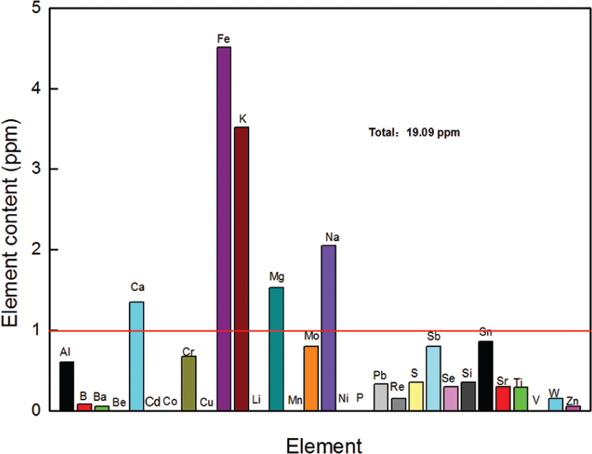
Impurity element content in carbon/carbon fiber composites.
However, these metal elements with high content are not necessarily harmful elements of crystal growth in high-temperature furnaces. It is possible that other elements destroy crystal growth or contaminate crystals. Some impurity elements will damage the growth of crystals even in a small amount. What kinds of impurity elements (such as S, P, B) are harmful to crystal growth, each crystal manufacturer’s requirements are different, often as a trade secret, and will not be detailed here.
Based on the above analysis, the impurities in the carbon/carbon fiber composite insulation material should be controlled to reduce or remove the impurity element content as much as possible. At present, there are two methods for removing impurities in the carbon/carbon fiber composite thermal insulation material, one is to exude impurities from the fiber composite material by a high-temperature heat treatment method through a long-time high temperature (>2000°C) process. In this case, the higher the temperature, the longer the heat treatment time, the more the impurities bleed out, and the purer the heat-insulating material, but this method consumes a large amount of electric energy. The other one is the chemical treatment method in which a high-temperature furnace (>2000°C) is charged with a fluorocarbon compound (such as chlorofluorocarbon) at high temperature. The chlorofluorocarbon releases a corrosive gas at high temperature, infiltrates into the carbon material, and reacts with the impurity elements, particularly the metal impurities in the carbon material. The impurity elements are then taken out to achieve the effect of removing the impurity elements. However, at this stage, hydrochlorofluorocarbons (HCFCs) are subjected to national control; many types of chlorofluorocarbons are banned, and there are very few manufacturers in the world who have such technology, SGL is one of them. We will also work on this in the next step.
Conclusion
In this work, lightweight carbon/carbon fiber composite thermal field insulation materials were prepared by the process method of long-cut carbon fiber needle-punching-forming-felt resin impregnation molding curing high-temperature carbonization and graphitization. The microscopic morphology, thermal conductivity, and impurity element content of carbon/carbon fiber composites were studied. So the following conclusions can be obtained:
A complete set of processes for preparing lightweight carbon/carbon fiber composite thermal field insulation materials is formed.
The direct needle-punching felt technology of carbon fiber reduces the carbonization process of the traditional pre-oxidation felt and improves the production efficiency. In addition, the carbon fiber material has a wide range of sources and can be purchased from domestic manufacturers, and it is no longer restricted by the raw material source of the pre-oxidized wire.
The long fiber is used to prepare the carbon fiber soft felt, and the prepared carbon/carbon fiber composite material realizes the fiber anisotropy, which can significantly reduce the thermal conductivity of the composite material in one specific direction (perpendicular direction). The thermal conductivity at 2000°C is only 0.38 W/(m·K).
The use of long fibers reduces fiber breakage, and high-temperature graphitization technology greatly reduces the content of impurities in the carbon/carbon fiber composite thermal field insulation material, which can be applied to the semiconductor field and other high-end equipments.
The preparation and performance of lightweight carbon/carbon fiber composite insulation materials will provide some advice for its application in crystal growth furnaces and other high-temperature insulation environments.
Footnotes
Declaration of conflicting interests
The author(s) declared no potential conflicts of interest with respect to the research, authorship, and/or publication of this article.
Funding
The author(s) disclosed receipt of the following financial support for the research, authorship, and/or publication of this article: The work was supported by the Project Funded by China Postdoctoral Science Foundation (2017M611757), Shanghai Science and Technology Talent Planning Project (19QB1402200), the Special Fund of the National Natural Science Foundation of China (51871146, 51803119 and 51771108), the Capacity Improvement Project for Municipal Universities in Shanghai by Shanghai Science and Technology Commission (19040501800), Chenguang Program supported by Shanghai Education Development Foundation and Shanghai Municipal Education Commission (18CG56) and the Innovation Program of Shanghai Municipal Education Commission (2019-01-07-00-10-E00053).