
Abstract
Light-weight hybrid composites of relevant industrial applications were prepared using surface functionalized hierarchical carbon fibers (f-CF), silane treated hollow glass microspheres (HGM), and a blend of polypropylene (PP) and maleic anhydride-grafted-styrene ethylene butylene styrene as the base polymer matrix. The f-CF were prepared by coating amine functionalized carbon nanotubes onto silane treated CF using an ultrasonic assisted electrophoretic deposition technique to improve fiber-matrix interfacial adhesion. For hybrid composition of 20 wt.% f-CF and 10 wt.% HGM, the tensile strength and modulus improved by ∼141 and ∼536% over neat PP while flexural strength and modulus increased by ∼118% and ∼583% respectively. Impact strength of 11.06 kJ/m2 was obtained and uniform dispersion and distribution of f-CF and HGMs was observed in Scanning electron microscope (SEM) images. Desirable reduction in density and melt viscosity along with improvement in composite stiffness were observed due to addition of HGM filler. Compared to PP, the crystallization temperature increased by ∼12°C while a maximum decrease of ∼5°C in melting temperature was obtained for the hybrid composites. Crystallinity of the hybrid composites decreased with an evident β crystal formation brought in by the nucleation.
Introduction
The inherent superior mechanical and thermal properties of reinforced composite materials have opened new avenues for their applications in addition to their being an alternative to metal parts in automotive and aerospace structures.1–6 The ability to tune and optimize different properties of composite materials7,8 based on different customer specific requirements and making them multi-functional has brought in a new trend in the research area. Especially, the use of CFs in structural and semi-structural composite component has been of focused interest lately due to its remarkable potential for offering high strength to weight ratio to products. 9 In the field of fiber reinforced thermoplastic composites the use of CFs with various polymer matrixes like polyamide (PA), polypropylene (PP), polyether-ether-ketone (PEEK), polyetherimide (PEI), etc. has been done extensively in the past decade.10–13 Low cost, easy processing, and recyclability of thermoplastics like PP and PA offers added advantages of use of CFs in composites over thermosets. Mechanical properties of such composite materials depend on an efficient load transfer from the base polymer to the reinforcing fiber. Here, the strength of the interphase between the fiber and polymer matrix plays a critical role. A strong interfacial adhesion among fiber and polymer can effectively increase the load transfer, and thereby, improve the mechanical properties of formulated composites. Therefore, various encouraging attempts have been made in the past to increase interfacial adhesion of CF with thermoplastic polymers.14–17 For instance, Zhang et al. 18 grafted amine-capped cross-linked polyphosphazenes onto CF surface. The modified CF showed interfacial shear strength (IFSS) of ∼11 and ∼32 MPa with PP and maleic anhydride-grafted-PP (MA-g-PP) respectively. Likewise, Servinis et al. 5 showed a 67% increase in IFSS of amine grafted CF relative to the control fibers when used with MA-g-PP. It was concluded that the increase in IFSS was due to the covalent cross-linking between the amine grafted CF and maleic anhydride co-monomer. Liu et al. 19 used a bio-inspired technique to functionalize CF with polydopamine and obtained an IFSS of 18.62 MPa with a blend of PP and MA-g-PP as the base polymer. Liu et al. also prepared composites using the polydopamine modified CF and obtained improvement in flexural strength, flexural modulus and unnotched Izod impact strength by 105%, 48% and 223% respectively. Luo et al. 20 carried out a layer by layer deposition of graphene oxide (GO) and polyethyleneimine (PEI) on CF surface to improve its interfacial adhesion with PP. Maximum IFSS of 10 MPa was obtained for a deposition cycle of 10 whereas the maximum increase in tensile strength of prepared composites was ∼32.6% compared to PP reinforced with pristine CF. Liu et al. 21 used solution dipping technique to coat CF with ethylene–methyl acrylate–glycidyl methacrylate (E-MA-GMA). IFSS measured for the coated CF using micro-droplet test revealed a value of 12.46 MPa which was ∼157.4% higher than with pristine CF. Besides, PP composites reinforced with the coated CFs showed 139.3%, 233.9% and 126.1% increment in ultimate flexural strength, impact energy and tensile strength. Shazed et al. 22 coated CF with CNTs using chemical vapor deposition (CVD). The CNT coated fibers reinforced PP composites showed tensile strength and modulus of 33.63 MPa and 3.52 GPa respectively.
In the present study, novel hybrid PP composites were prepared using surface functionalized hierarchical carbon fibers (termed f-CF hereafter) and silane treated HGM. The main objective of the present work was to obtain high strength yet very lightweight PP composites. In order to achieve this, enhancement in fiber-matrix interfacial adhesion was induced by considering a dual surface modification approach for CF. Initially, the chemical nature of the CF surface was modified by grafting amine functionalized silane groups. Next, amine functionalized CNTs were coated on the silane grafted CF using u-EPD. It was envisaged that maleic anhydride-grafted-styrene ethylene butylene styrene (MA-g-SEBS) which was used as both compatibilizer and impact modifier will form chemical linkage with the f-CF and the coated CNTs will act as mechanical anchoring sites to improve adhesion. In addition, HGM particles were used in the hybrid composite formulations to primarily reduce their bulk density, and thereby, improve the specific mechanical properties of the composite material.
Materials and methods
Materials
Injection moulding grade PP was procured from Reliance Polymers, India with a trade name HII0MA. It has a melt flow rate (MFI) of 11g/10 min at 230 °C/2.16 kg measured under ASTM D 1238. CF with a single filament diameter of 6.97 μm and density of 1.798 g/cm3 was obtained from Jalark Carbon products, India. Lightweight HGM fillers (grade iM30K) were provided by 3M, India. The fillers have an average diameter of 20 μm and density of 0.46 g/cm3. MA-g-SEBS having a density of 0.91 g/cm3 and tensile strength of 18 MPa was purchased from DZBH New Material, China. Silane coupling agent 3-Aminopropyltriethoxysilane (APTES) was purchased from TCI chemical India Pvt. Ltd.
Surface modification of CF
Initially, the commercial sizing on CF was removed by desizing it in acetone using Soxhlet extraction for 20 h and at 70°C. The desized CFs were then filtered and dried in oven. To obtain -OH groups on the CF surface, the desized CFs were dipped in a dilute piranha solution containing H2SO4 and H2O2 in the ratio of 3:1 for 20 min. The fibers were thereafter dried in oven which was followed by silane treatment in a 20% concentrated APTES solution to obtain amine functionalized CFs. In order to coat this amine functionalized CF with amine functionalized CNTs, we adopted ultrasonic-assisted electrophoretic deposition technique (u-EPD). Here, the functionalized CFs were connected to the negative terminal, and hence, acted as the cathode and the counter electrode made of a cylindrical aluminum tube was made as anode by connecting it to the positive terminal of power supply. It was envisaged that the amine functionalized CNTs carrying a positive charge will get deposited on the CF surface. Thus, the surface modified CFs for this study were prepared which shall be termed as Schematic representation of surface modification process followed for CF in the study: (a) sized CF obtained from vendor, (b) desized CF obtained after removal of the epoxy sizing, (c) -OH functionalized CF obtained after Piranha treatment of the desized CF, (d) Silane treatment of the -OH functionalized CF, (e) NH2-CNT coated CF obtained by carrying out u-EPD on previously obtained silane treated CF, shortly named here as f-CF. Figure (f) represent a hybrid composite containing f-CF and silane treated HGM filler within a PP based matrix.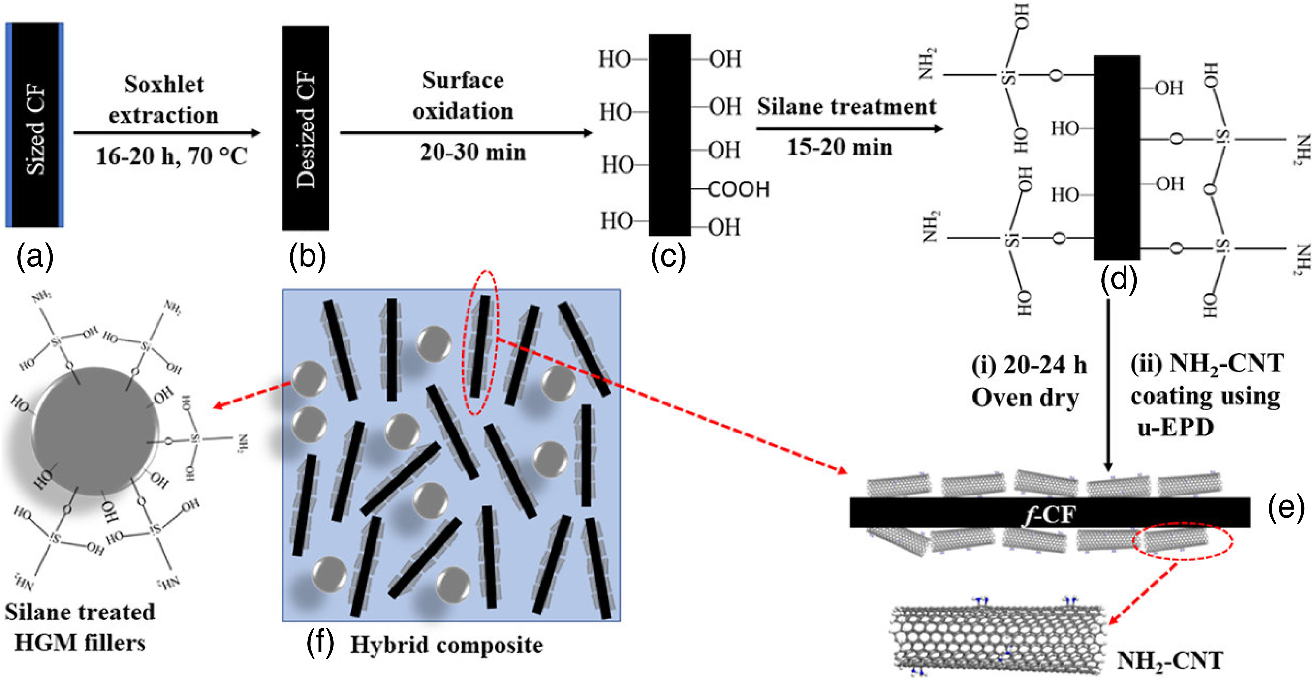
Surface treatment of HGM fillers
The HGM fillers were subjected to hydroxylation initially using sodium hydroxide (NaOH) solution. 10 gm of HGM was taken in a 0.5 mol/L of NaOH solution and stirred at 90°C for 1 h. The solution was then cooled down, filtered and washed using distilled water and was kept for drying for 10 h. For the silane treatment of the hydroxylated HGM fillers, APTES solution in ethanol was used along with n-propylamine as the catalyzing agent. The solution was stirred at 60°C for 1 h, after which it was filtered and washed. The surface treated HGM fillers were then dried and used in composites. The complete details of the modification process can be found elsewhere. 23
Sample preparation
Sample designations and formulations of different composites.
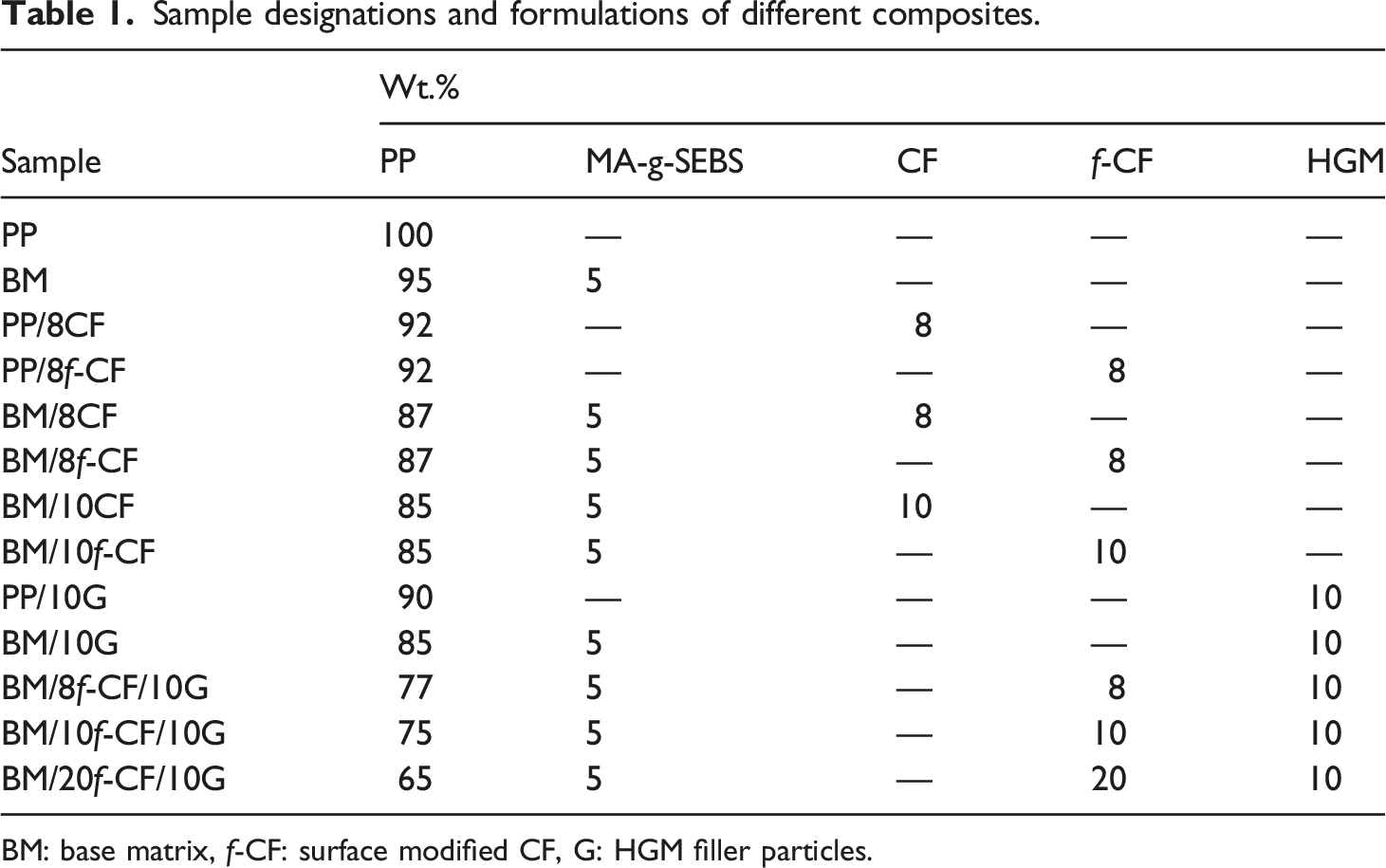
BM: base matrix, f-CF: surface modified CF, G: HGM filler particles.
ATR-IR
To identify nature of different chemical bonds within the prepared composites, attenuated total reflectance (ATR) infrared spectroscopy (ATR-IR) was carried out using PerkinElmer spectrophotometer (L1600400 Spectrum TWO DTGS, UK). The measurement was carried out at a resolution of 4 cm−1 in the frequency range of 4000–500 cm−1 by directly placing the sample on the surface of the Zinc Selenide (ZnSe) ATR crystal.
Density measurement
The density of all the prepared samples were measured at ambient temperature using ASTM D792-13. The theoretical density, ρ
th
, of composite samples were calculated using the following relation.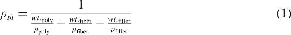
Mechanical testing
Tensile testing of samples was conducted under ISO 527–2 standard in Universal Testing Machine (UTM) (Model: 3365, Make: INSTRON®). The crosshead speed was maintained at 10 mm/min. Charpy unnotched impact strength of the composites was measured in accordance with ISO 179-1/1eU in a Tinius Olsen impact tester (Model: Impact 104). Three-point flexural strength of the samples was estimated using UTM at 2 mm/min crosshead speed in line with ISO 178. The sample dimensions for both the impact and flexural tests were 80 × 10 × 4 mm3 in which span length of 16 × 4 mm was kept for the flexural test. Average of at least five samples are reported here for all the estimates from mechanical testing.
Morphology
The morphological analysis of the cryo-fractured composite samples was carried out through FE-SEM [Model: MIRA 3 LM, Make: TESCAN]. Gold-palladium alloy was sputter coated on the fractured surfaces prior to the analysis.
Rheological analysis
The melt rheological analysis of the prepared samples was carried out at 185°C using a parallel plate of diameter 25 mm and with the plate gap maintained at 1.4 mm during the analysis. A frequency sweep was done at a frequency range of 0.05–500 rad/s within the linear viscoelastic range.
Thermal analysis
Differential scanning calorimetry (DSC) analysis was carried out in DSC 25, Make: TA instruments for the samples to evaluate the melting and crystallization temperature along with their enthalpy. Initially, samples were subjected to a heating cycle from room temperature to 200°C in order to eliminate any previous thermal history. Thereafter, the samples were cooled down to −50°C and again heated to 200°C. The crystallization and the melting temperature were noted during the second cooling and heating cycle respectively. The temperature rate was fixed at 5 °C/min for each scan and at the end of every cooling or heating step an isothermal condition was maintained for 2 min. The percent crystallinity (% X
c
) of the samples was evaluated by using the following 
Results and discussions
ATR-IR analysis
The successful formation of different bonds between the reinforced f-CFs and HGMs with the base polymer matrix within the composites and their hybrids is duly confirmed by the ATR-IR analysis. Figure 2 shows ATR-IR spectra of PP and BM along with different composites. It can be observed in Figure 2(a) that PP shows C-H stretching at 2961, 2925, and 2870 cm−1 while CH2 deformation and symmetric CH3 deformation is observed at 1452 and 1375 cm−1. Peaks at 1169, 992, and 843 cm−1 are characteristic vibrational peaks of isotactic PP.
24
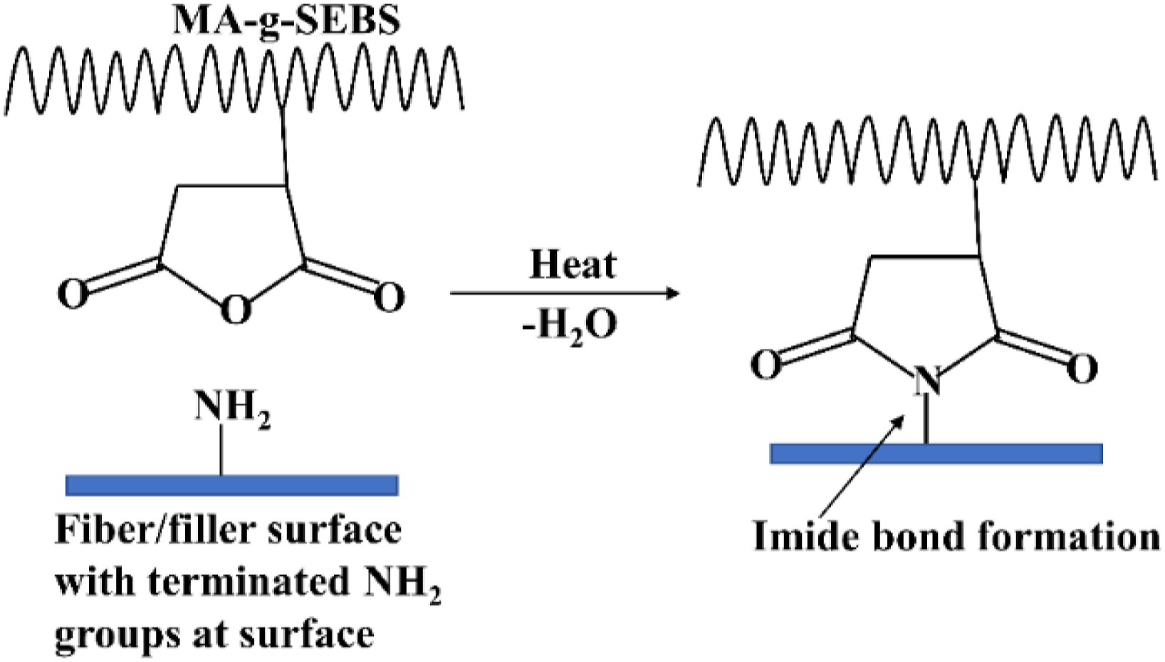
BM, containing a 5 wt.% of MA-g-SEBS within PP matrix, shows absorption peaks of C-H bonds at 2957, 2922, and 2874 cm−1 belong to the symmetric and asymmetric vibrations of the C-H bonds in the CH2 groups. The asymmetric stretching of C-H bonds of methyl groups present in PP and ethylene-butylene block of SEBS and PP is demonstrated by the transmittance peak at 1451 cm−1 whereas peak at 1374 cm−1 represents deformation vibrations of the C-H bonds in the CH2 groups. Furthermore, the peak at 696 cm−1 represents the out-of-plane bending of C-H bonds of the aromatic ring present in SEBS. Peak at 1780 cm−1, shown in the inset image of Figure 2(a), represents stretching vibration of C=O group present in the maleic anhydride (MA). The reaction among MA-g-SEBS and -NH2 groups present on the treated surface of HGM and f-CF, as shown in the Figure 3, was envisioned to improve interfacial adhesion. After the incorporation of HGM and f-CF separately and in combination into the BM, the C=O stretching peak previously observed at 1780 cm−1 disappears and the formation of absorption peaks of O=C-N-C=O (imide carbonyl group) at ∼1700 cm−1 is observed for all the composites.
25
The formation of cyclic imide was thus confirmed by the C=O stretching vibration at 1704 and 1743 cm−1 for BM/10G, 1704 and 1748 cm−1 for BM/10f-CF, and 1702 and 1771 cm−1 for BM/10f-CF/10G, respectively as shown in the insets of Figure 2(b). ATR-IR spectra of (a) PP and BM, and (b) BM/10G, BM/10f-CF, and BM/10f-CF/10G. Respective inset images shows zoomed in scan of the particular sample. Schematic representation of the formation of imide bond between MA-g-SEBS and terminated -NH2 group available at the surface of f-CF or HGM.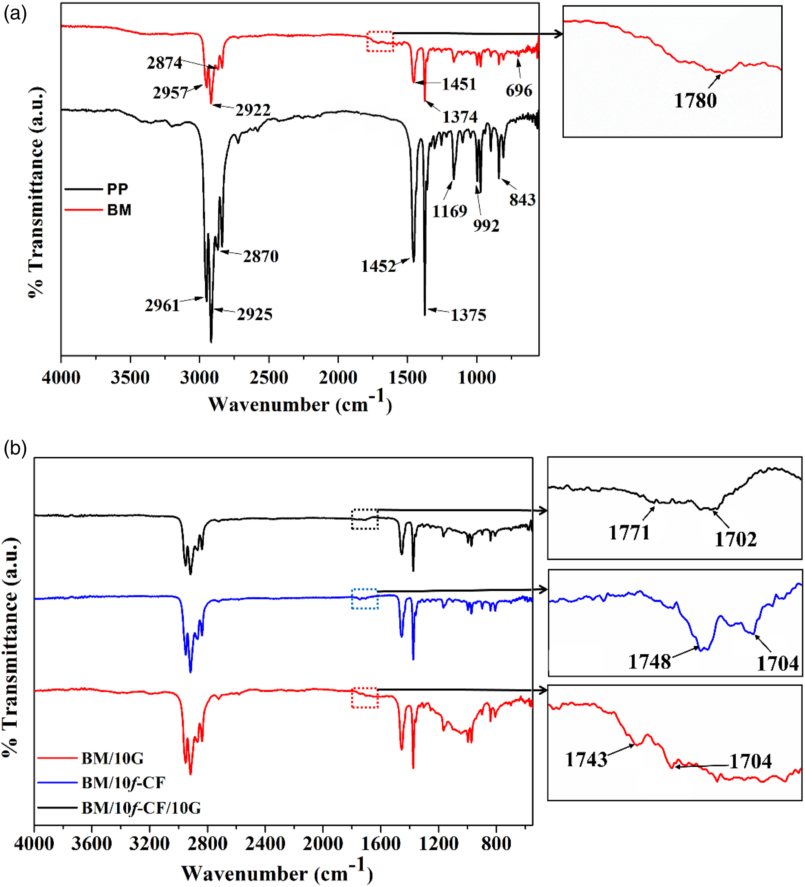
Various observations were earlier made,25–29 which are pertinent to the formation of imide bond similar to the present study. It is to be noted here that MA-g-SEBS used in the present study contains only 1.5 wt.% of MA, and a total of only 5 wt.% of MA-g-SEBS was used in the composite formulation. Hence, peaks intensity arising due to MA and its reaction with other groups is comparatively small within the ATR-IR scans.
Density
Figure 4 depicts the theoretical and density estimates of the composites. The theoretical density for all the compositions were calculated using equation (1) mentioned earlier. Measured density of PP and BM was ∼0.91 g/cm3 which is equivalent to their theoretical density. In case of the composites reinforced with only CF (treated or untreated), the density increased with increasing CF wt.%. Whereas for the composites containing HGM fillers the bulk density was relatively lower. Illustration of theoretical and measured density values for PP, BM, and all the composites prepared in the study.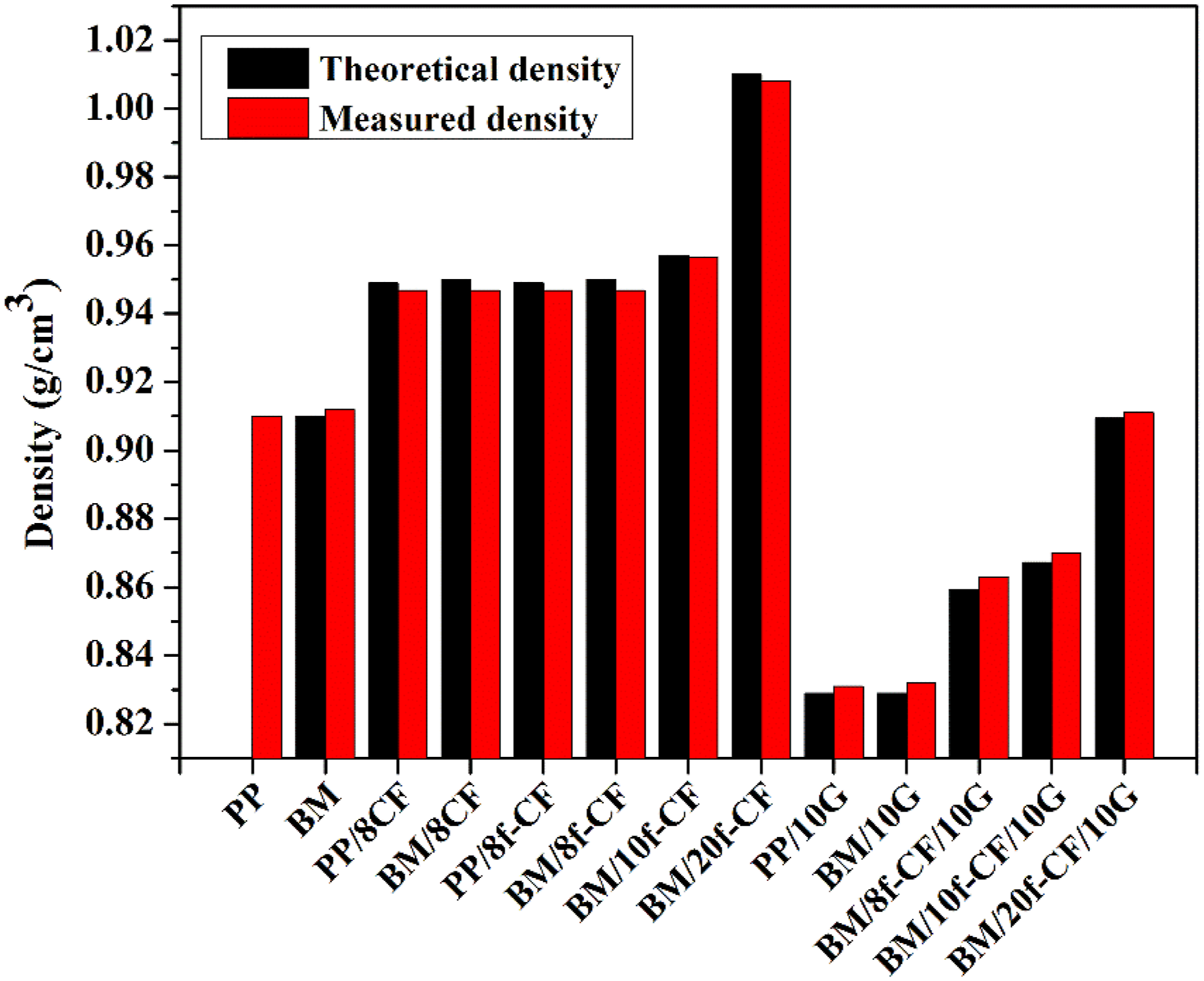
It is apparent from Figure 4 that, when compared to the theoretical densities, the measured densities of all the compositions are slightly different. This is since in composite preparation there may have been generation of voids which led to a reduction in density in some cases and whereas increase in density may have possibly occurred due to the breakage of few HGM fillers during processing. However, the primary aim of using HGM fillers for reducing composite density was achieved as can be observed by the density reduction percentage for respective hybrid composites BM/8f-CF/10G (down by ∼9% versus BM/8f-CF), BM/10f-CF/10G (down by ∼9% versus BM/10f-CF), and BM/20f-CF/10G (down by ∼10% versus BM/20f-CF). HGM fillers having very low density of ∼0.46 g/cm3 and a crushing strength of ∼28,000 psi30,31 helps to reduce the bulk density of the composites without their significant breakage under severe shear mixing conditions during composite preparation.
Mechanical properties
List of all the mechanical properties estimated for the prepared composites.
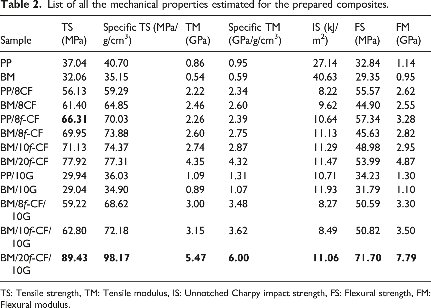
TS: Tensile strength, TM: Tensile modulus, IS: Unnotched Charpy impact strength, FS: Flexural strength, FM: Flexural modulus.
Tensile properties
The tensile strength of neat PP was 37.04 MPa, which reduced to 32.06 MPa upon blending it with 5 wt.% MA-g-SEBS to prepare the BM for composites, as observed in Table 2. This reduction was obvious due to the lower inherent tensile strength of MA-g-SEBS which is ∼18 MPa. 32 Incorporating 8 wt.% CF increases the tensile strength of both PP and BM as can be observed for PP/8CF (56.13 MPa) and BM/8CF (61.40 MPa). The higher strength of BM/8CF compared to PP/8CF was due to the use of MA-g-SEBS which acted as a coupling agent in increasing the interfacial adhesion among CF and BM. 33 The CFs used in the present study have epoxy as the sizing material which may have provided a polar-polar interaction site for the BM containing polar MA group. Wong et al. have also earlier stated the possibility of chain entanglements and co-crystallization of coupling agent like MA-grafted-PP (MA-g-PP) with the non-polar PP matrix to subsequently provide mechanical integrity to the base polymer and help increase the tensile strength of PP/CF composites. 33 Furthermore, PP/8f-CF reinforced with 8 wt.% f-CF displayed even higher tensile strength (66.31 MPa) compared to both PP/8CF and BM/8CF. It is most probably due to the presence of a forest of CNTs on the surface of f-CF (explained later in Morphological analysis), which provides a better mechanical anchoring with the PP. The effective load transfer form polymer matrix to fiber thus increases, which ultimately improves the strength of PP/8f-CF. It also showed that without any coupling agent and using only the f-CF, the tensile strength of PP/8f-CF improved by ∼79% over neat PP. Furthermore, in comparison to PP/8f-CF, the composite BM/8f-CF had an added advantage of using BM instead of PP which provided the latter to exhibit a higher tensile strength of 69.95 MPa. As previously explained in the ATR-IR analysis under FTIR analysis, there is a presence of cyclic imide bond among BM and the reinforced f-CF which is responsible for increasing the fiber-matrix adhesions. Thus, the combined effect of mechanical interlocking supported by functionalized CNTs and the formation of chemical bond among reinforced f-CF and BM have significantly improved the tensile strength of BM/8f-CF. Similarly, BM/10f-CF and BM/20f-CF with higher wt.% of f-CF displayed even higher tensile strength of 71.13 and 77.92 MPa, respectively.
Introducing HGM fillers into PP and BM resulted in a decrease in the tensile strength as observed for PP/10G and BM/10G in Table 2. A tensile strength of ∼29 MPa was observed for both HGM filled composite. The decrease in tensile strength can be attributed to the spherical shape of the HGM fillers which makes them a stress concentrator 34 in the continuous matrix and also during the tensile test, the filler particles breakdown due to limited strength of its glass shell. 35 Furthermore, in case of the hybrid composites the tensile strength initially decreased for BM/8f-CF/10G (59.22 MPa) and BM/10f-CF/10G (69.80 MPa) in comparison to their counterpart BM/8f-CF (69.95 MPa) and BM/10f-CF (71.13 MPa), respectively. The reduction in the tensile strength was evident due to the incorporation of HGM fillers in the hybrid formulations. But a positive hybridization effect was observed for BM/20f-CF/10G with a significant increase in its tensile strength (89.43 MPa) over BM/20f-CF (77.92 MPa). The tensile strength for BM/20f-CF/10G was ∼141% higher than neat PP. It can be concluded from the above observations that the strength loss due to HGM addition in hybrid composite was duly compensated and even crossed the strength of BM/20f-CF. A similar observation of positive hybridizing effect earlier was made by Kumar et al. 2 for bamboo fiber reinforced hybrid composites with PP as the base matrix.
Comparative analysis of tensile strength of PP composites prepared by reinforcing different surface modified CF.
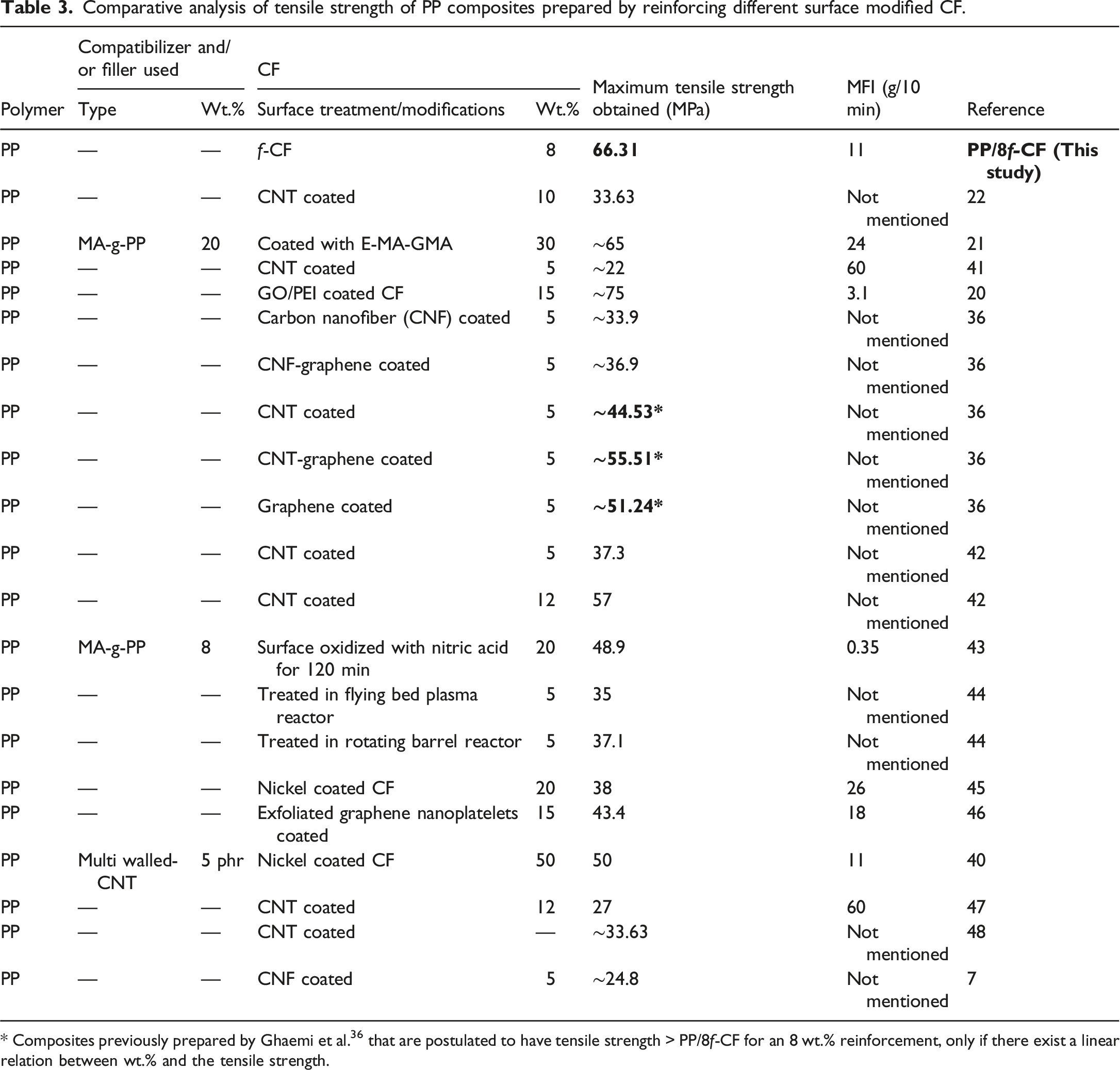
* Composites previously prepared by Ghaemi et al. 36 that are postulated to have tensile strength > PP/8f-CF for an 8 wt.% reinforcement, only if there exist a linear relation between wt.% and the tensile strength.
It is also to be noted here that the grades of PP used for the comparative analysis are different as evident from their respective MFI in Table 3. Properties of composites vary with varying MFI 39 since MFI also correlates to the molecular weight of the polymer. For an apple-to-apple comparison, the MFI of the PP used should be identical. Nonetheless, comparing composites having PP with MFI of 11 g/min, 40 PP/8f-CF still exhibits a higher strength, as observed in Table 3.
Similar to the tensile strength, the tensile modulus of the composites varied with the addition of fiber and filler particles. Compared to PP (0.86 GPa) the tensile modulus decreased for BM (0.54 GPa) due to the addition of MA-g-SEBS. Whereas the incorporation of 8 wt.% CF and f-CF separately into BM increased the tensile modulus by ∼11 and ∼15% as observed for BM/8CF (2.46 GPa) over PP/8CF (2.22 GPa) and BM/8f-CF (2.60GPa) over PP/8f-CF (2.26 GPa), respectively. This increase was due to the addition of stiff fibers and also probably due to the enhanced fiber-matrix interfacial adhesion in case of composites with BM. Furthermore, with increasing f-CF wt.% the tensile modulus increased as observed for BM/10f-CF (2.74 GPa) and BM/20f-CF (4.35 GPa) in Table 2. PP/10G (1.09 GPa) and BM/10G (0.89 GPa) have showed higher modulus compared to PP and BM since the HGM fillers induced stiffness to the composites. Similarly, increasing trend in tensile modulus of the hybrid composites was observed. BM/20f-CF/10G showed tensile modulus of 5.47 GPa which was ∼536% higher than PP and also the highest among all the hybrid composites. It is apparent that this was possible due to stiffness increase supported by both the f-CF and HGM addition. It is to be noted here that HGM fillers not only helped in reducing the bulk density of the composites but also improved the stiffness.
Ashby plot
For lightweight application of composite materials, the understanding of specific property is very crucial from the design perspective of components. Relation between two specific properties can be shown in an Ashby plot for different materials, and hence, the plot itself can serve as a material selection chart.35,49 In the present study, the results have been compared with previously reported data via Ashby plot as shown in Figure 5. It can be observed for the prepared composites in the Ashby plot that, with increasing incorporation of f-CF from 8 to 20 wt.% the specific tensile strength increased, and it reached a highest value of 98.17 MPa/g/cm3 for the hybrid composite BM/20f-CF/10G. In comparison to its counterparts having similar or higher wt.% of CF the specific tensile strength was lower as observed for PP/CF20_1, PP/CF27, and PP/CF30_1 in Figure 5. However, the specific tensile modulus of the composites in the present investigation were comparatively lower which was probably due to the use of MA-g-SEBS having lower tensile properties. In addition, tensile properties of the composites also depend on the types of PP (homopolymer, copolymer), grades of PP (having different melt flow index); wt.%,
50
length and grade (low, intermediate, high, and ultrahigh modulus) of CF; etc. Nonetheless, the incorporation of prepared f-CF displayed better tensile strength at low fiber wt.% as a result of improved interfacial adhesion and the use of HGMs improved the specific properties of the composites. The hybrid composite, BM/20f-CF/10G, showed the highest specific tensile modulus of ∼6 GPa among all the formulations prepared in the present study. Ashby plot representing specific tensile strength and modulus of the composites prepared in the present study and previously reported data from various sources. Refer supplementary information for the references of the previously reported data. Note: CF: Carbon fibre, CNT: Carbon nanotube, CNF: Carbon nanofiber, E-MA-GMA: ethylene–methyl acrylate–glycidyl methacrylate, G: Graphene, FBDR: Flying bed plasma reactor, RBR: Rotating barrel reactor, Ni: Nickel coated, exG-nano: Exfoliated graphene nanoplatelets. Designation of samples having only CF implies that the reinforced CF was used without any surface treatment, whereas designation of composites containing surface treated CF have treatment process or name of coated material before CF. The wt. % of reinforcement in composite is displayed adjacent to CF, and a digit after underscore represent to differentiate two composite having similar designation.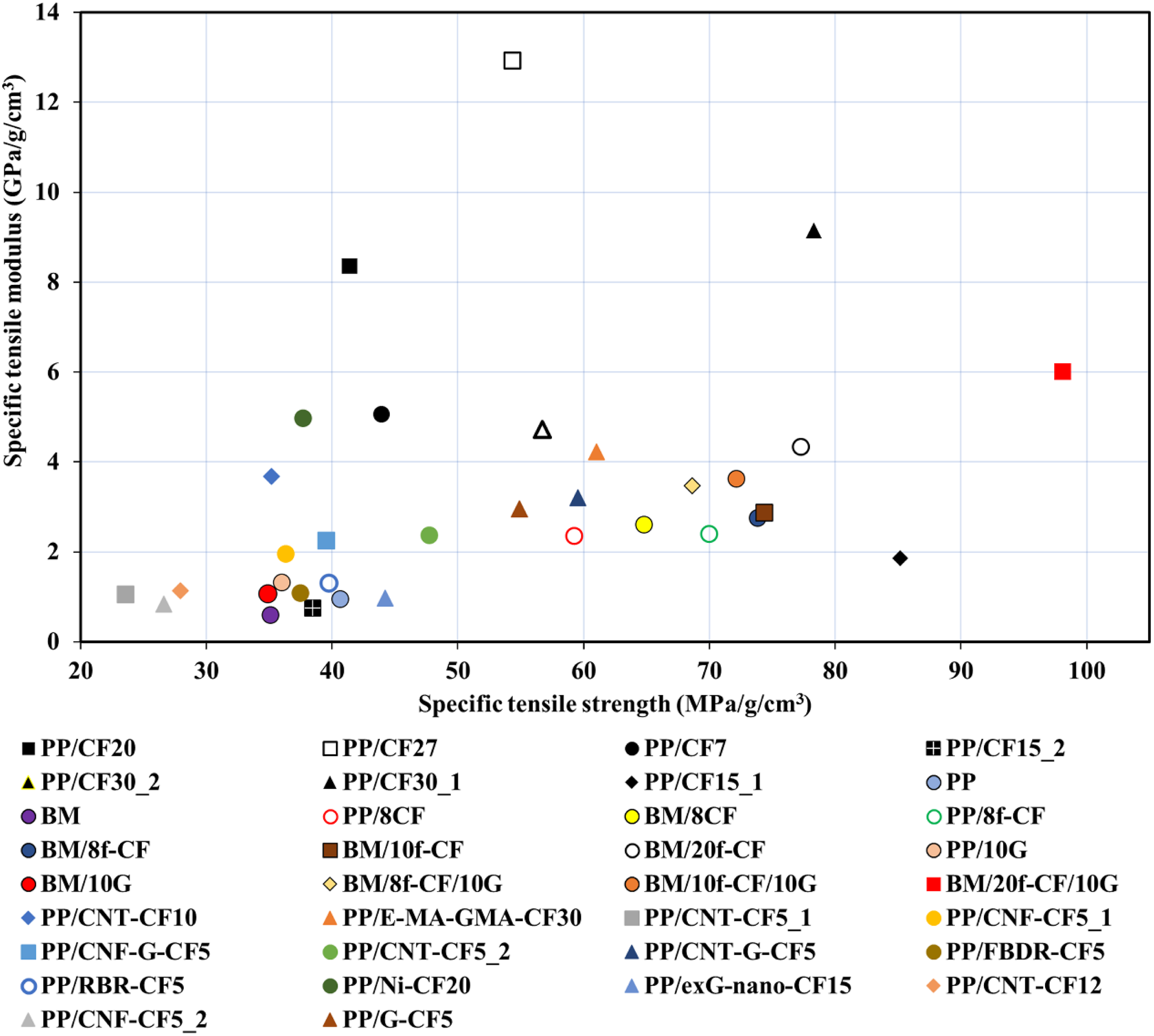
Impact strength
The unnotched Charpy impact strength of the composites was estimated and is reported in Table 2. The PP used here showed an impact strength of 27.14 kJ/m2, which increased by ∼50% for BM with the addition of only 5 wt.% MA-g-SEBS. At 8 wt.% of CF or f-CF, composites with BM showed higher impact strength than those with PP as observed for BM/8CF (9.62 kJ/m2) over PP/8CF (8.22 kJ/m2) and BM/8f-CF (11.13 kJ/m2) over PP/8f-CF (10.64 kJ/m2). With increasing f-CF wt.% from 8 to 20, the impact strength increases further and a value of 11.47 kJ/m2 was obtained for BM/20f-CF. Despite the inherent brittleness of CF and its higher content employed, the relative increment in impact strength was probably due to improved fiber-matrix interfacial adhesion and the use of MA-g-SEBS in BM. Furthermore, PP/10G and BM/10G containing 10 wt.% HGM fillers showed impact strength of 10.71 and 11.93 kJ/m2, respectively. In case of the hybrid composites containing both the fillers, f-CF and HGM, a slight decrease in impact strength was observed compared to individual composites containing f-CF and HGM separately. For instance, BM/8f-CF/10G showed an impact strength of 8.27 kJ/m2 which was less than that of BM/8f-CF (11.13 kJ/m2) and BM/10G (11.93 kJ/m2). Similar observations were made for BM/10f-CF/10G (8.49 kJ/m2) and BM/20f-CF/10G (11.06 kJ/m2) as well. With increasing fiber and filler wt.%, the number of stress concentration points usually situated around the fiber and filler surface might have also increased which led to an easy propagation of micro-cracks resulting in reduced impact strength in the hybrid composites. 51
Flexural properties
The flexural strength and modulus values of the prepared composites are presented in Table 2. PP displayed a flexural strength and modulus of 32.84 MPa and 1.14 GPa, which decreased to 29.35 MPa and 0.95 GPa, respectively for BM. Upon incorporation of CF, the flexural properties significantly improved for PP/8CF and BM/8CF with display of higher flexural strength and modulus of 55.57 MPa and 2.62 GPa than 44.90 MPa and 2.55 GPa. Addition of f-CF further improved the flexural strength and modulus estimates to 57.34 MPa and 3.28 GPa, respectively for PP/8f-CF due to the improved reinforcing effect brought in by the surface modification of CF. Furthermore, incorporating f-CF into BM and increasing its wt.% showed a positive increment in flexural properties as observed for BM/8f-CF (45.63 MPa, 2.82 GPa), BM/10f-CF (48.98 MPa, 2.95 GPa), and BM/20f-CF (53.99 MPa, 4.87 GPa) in Table 2. HGM incorporation showed a slight increase in flexural properties for PP/10G and BM/10G compared to their estimates for base polymer PP and BM respectively. While in case of the hybrid composites a synergistic and positive hybridization effect was observed which led to a higher flexural strength and modulus compared to their binary compositions. For instance, BM/8f-CF/10HGM showed flexural strength and modulus of 50.59 MPa and 3.30 GPa which was higher than those shown by the binary compositions BM/8f-CF and BM/10G separately as can be observed in Table 2. Similar observations were made for BM/10f-CF/10HGM and BM/20f-CF/10HGM, with the highest flexural strength and modulus of 71.70 MPa and 7.79 GPa shown by the latter among all the compositions investigated in this work. In comparison to neat PP, the increase in flexural strength and modulus displayed by BM/20f-CF/10HGM was quite significant to the order of ∼118 and ∼583% higher, respectively.
Morphological analysis
The SEM micrographs obtained for the CF and f-CF is shown in Figure 6. It can be observed from Figure 6(a) that the CF containing an epoxy sizing exhibits a smooth surface, whereas f-CF in Figure 6(b) shows a forest of CNTs covering the surface of CF. Thus, visual confirmation of successful coating of -NH2-CNT using u-EPD was confirmed. The illustration shows SEM micrographs of (a) pristine CFs and (b) f-CF. Respective figures on right indicates zoomed in images.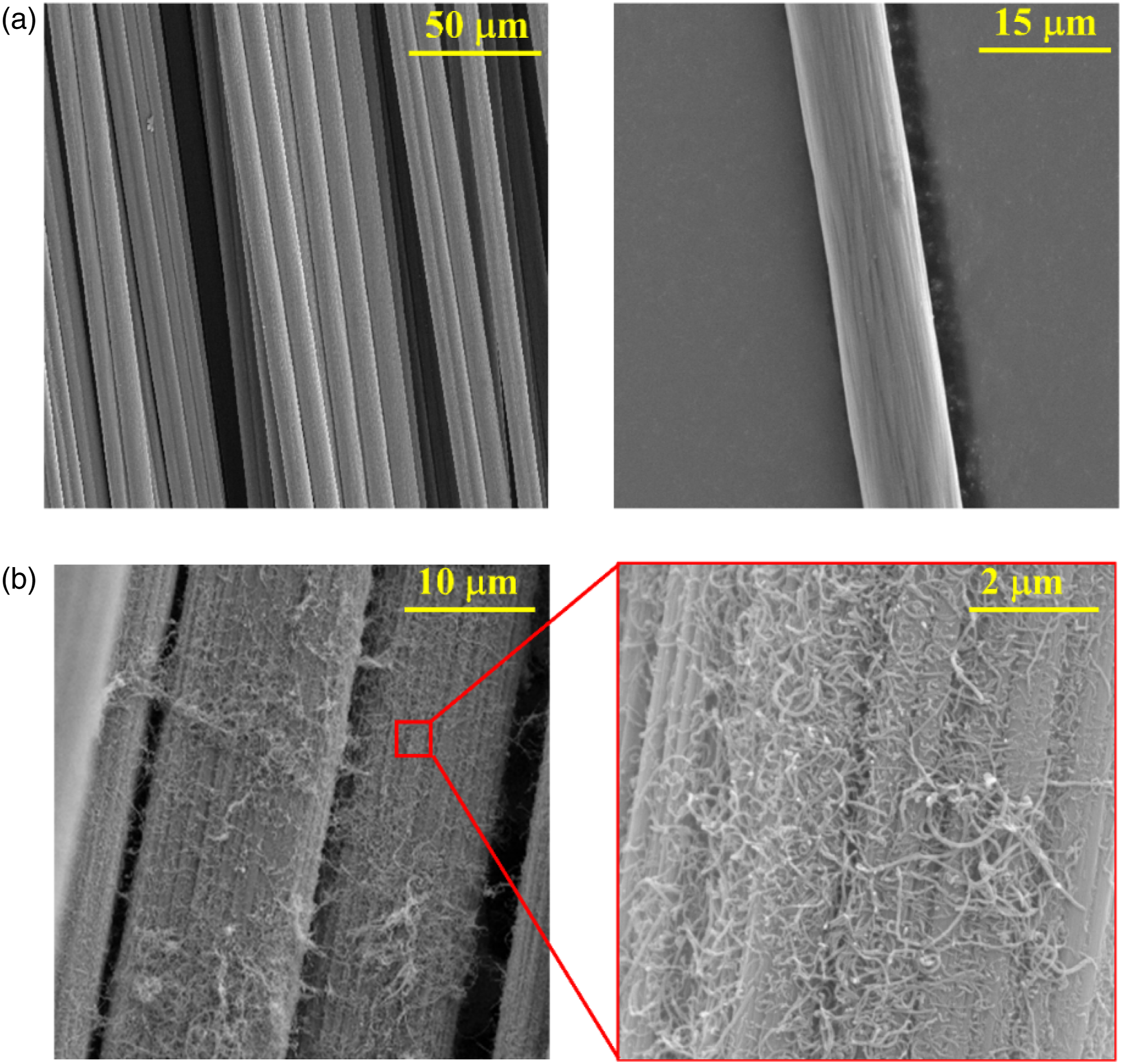
The SEM images of cryo-fractured hybrid composite samples are presented in Figure 7(a)–(c). It can be observed for the hybrid composites that HGM and f-CF have been nicely dispersed and distributed within the BM with visibly no agglomerations. The fiber filaments have been nicely separated from their individual tows during mixing and a negligible breakage of HGM fillers was observed. All these visible observations thus support the use of optimum processing parameters during the composite fabrication. Furthermore, Figure 7(d) show f-CF embedded by the BM, thus confirming a good fiber-matrix interfacial adhesion brought in due to the surface modifications of the fiber which possibly led to formation of chemical bonds as discussed in the FTIR ATR-IR analysis. Similarly, the silane treated HGM fillers were also nicely embedded by the BM and its evident as shown in Figure 7(e). SEM images of cryo-fractured surface of (a) BM/8f-CF/10G, (b) BM/10f-CF/10G, and (c) BM/20f-CF/10G. Zoomed in images of (d) f-CF and (f) HGM showing good embedding within BM.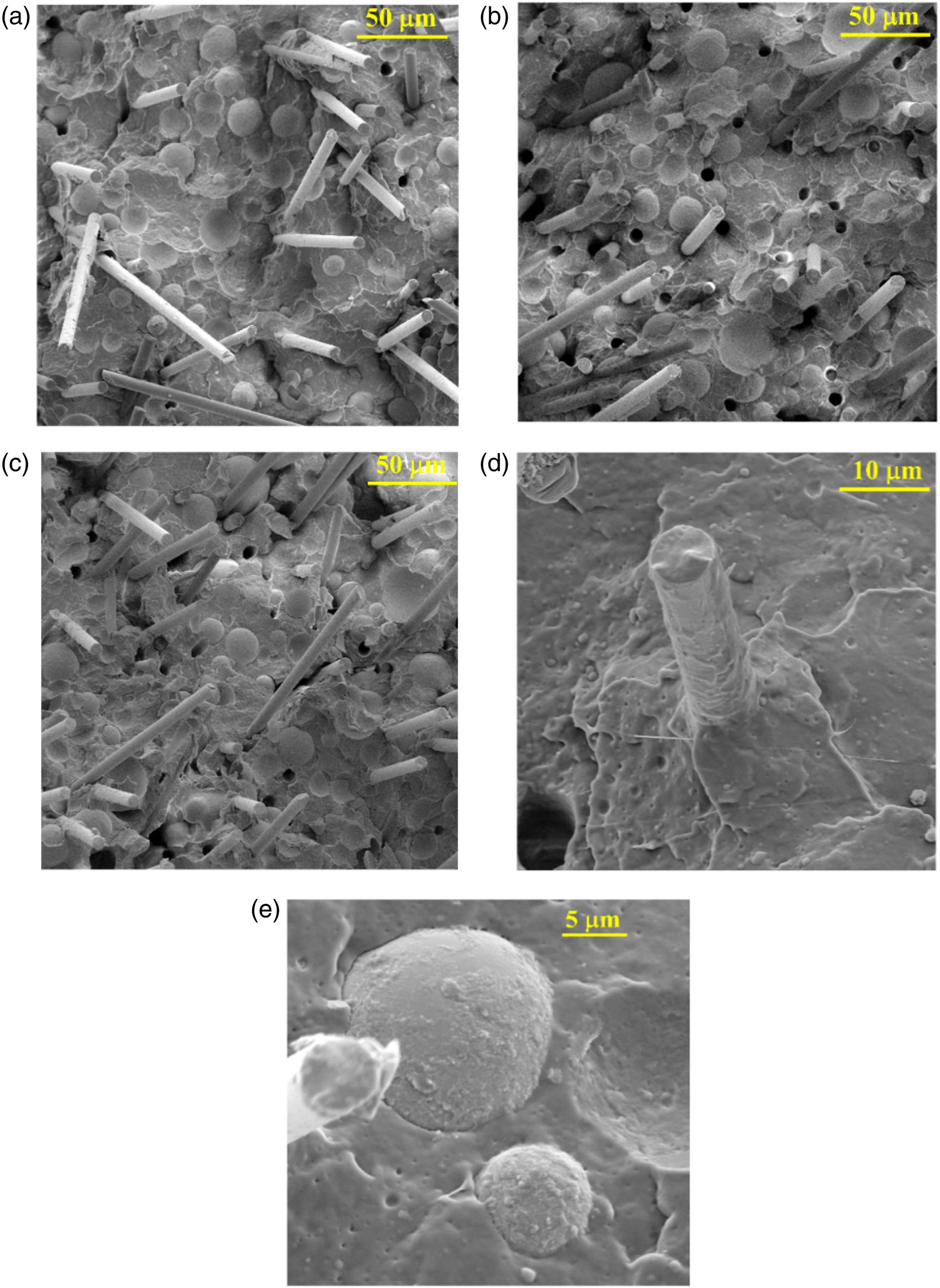
In addition, the SEM images of the composites reinforced solely with CF or f-CF are depicted in Supplementary Information Figure S1. Fiber pull-out was obvious as observed in the images, for all the composites. However, with improved interfacial adhesion the number of fiber pull-out reduced, making the composites stronger under tensile load as observed for PP/8f-CF versus PP/8CF, and BM/8CF versus BM/8f-CF in Table 2.
Melt behavior of composites
The melt viscosity of the composites was obtained from the rheological analysis. Figure 8 depicts the variations in η* as a function of ω in a log-log plot for the composite systems, and the η* values at 0.05 and 500 rad/s are listed in Table 3. A shear thinning behavior was observed for PP and all the formulations. At lower ω, BM showed slightly higher η* but at higher ω it showed lower η* than PP. Addition of 8 wt.% f-CF to BM increased the η* of the composite BM/8f-CF due to the restrictions in flow created by the incorporated fibers. With further addition of 10 and 20 wt.% f-CF, the η* increased even more as observed for BM/10f-CF and BM/20f-CF, respectively in Table 4. For BM/10G containing only 10 wt.% HGM fillers, the variation in η* with ω was noticed to be similar and even lower than PP. The reduced η* values of BM/10G were due to the ball bearing effect of HGM fillers as also reported earlier.
52
In case of the hybrid composites, η* increased as expected due to higher total wt.% of fillers and fibers in comparison to only f-CF reinforced composites. For instance, the η* at 0.05 and 500 rad/s for BM/8f-CF/10G was 5520 and 305 Pa.s whereas for BM/8f-CF it was 3610 and 261 Pa.s, respectively. This was because the former had a total of 18 wt.% (8+10) reinforcement, higher than the latter with only 8wt.% reinforcement. Variations of complex viscosity (η*) as a function of angular frequency (ω) for PP and different composites prepared in the study. Complex viscosity, η* of composites at different angular frequencies, ω.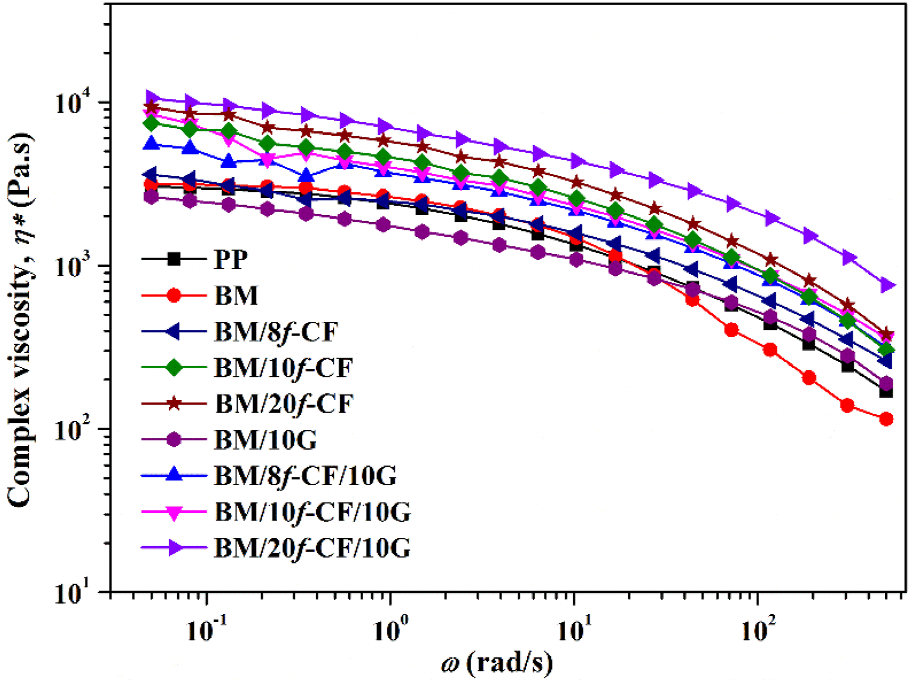
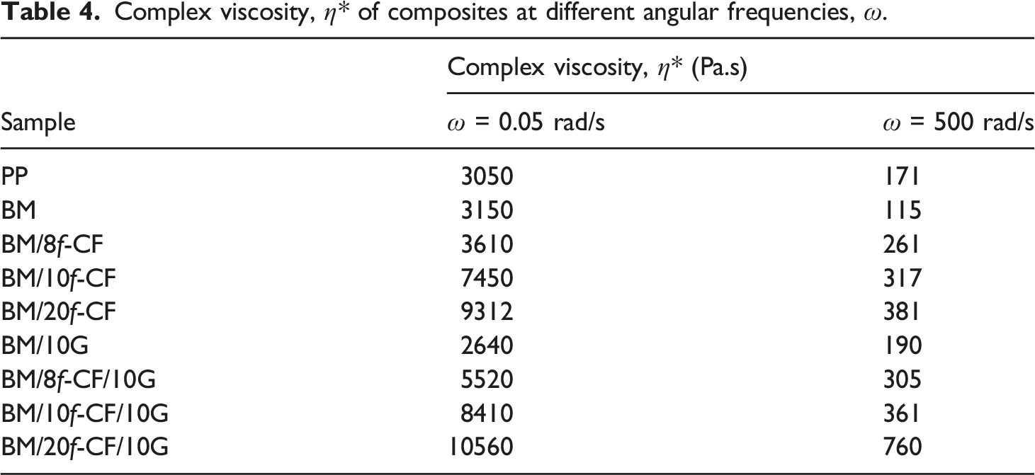
Similar observations were made for BM/10f-CF/10G and BM/20f-CF/10G over BM/10f-CF and BM/20f-CF, respectively as seen in Table 3. Interestingly, it can be observed that the hybrid composites BM/8f-CF/10G and BM/10f-CF/10G in spite of having a higher total wt.% of reinforcement exhibited lower values of η* in comparison to BM/10f-CF and BM/20f-CF, respectively. Thus, the positive effect of the presence of HGM fillers in reducing the viscosity, in addition to composite part weight reduction, was apparent, thereby, ensuring processing benefits during product manufacturing.
Thermal properties of composites
The thermal analysis of PP and composites were analyzed in a DSC and the obtained endothermic and exothermic peaks corresponding to the melting and crystallization temperature is plotted against temperature as shown in Figure 9. Obtained parameters like crystallization temperature (T
c
), melting temperature (T
m
), and ΔH from the DCS scan is listed in Table 5 along with the estimated crystallinity measured in %X
c
. It can be observed that the T
c
of all the composites and also that of BM increased with respect to neat PP due to the restrictions in the polymer chain mobility created by the hybrid inclusions. Similar observations were earlier made for hybrid compositions of fly-ash and sisal fiber by Maurya et al.
53
and HGM and bamboo fiber in PP by Gogoi et al.
54
A maximum increase of ∼12°C was observed in T
c
for the hybrid composite BM/20f-CF/10G. On the other hand, the T
m
of the composites shifted to a lower temperature in comparison to PP, as apparent from Table 5. The decrease in the T
m
may have occurred due to decreasing crystalline structure within the composite with increasing filler loading. A maximum reduction of ∼5°C in T
m
was observed for the hybrid composite BM/20f-CF/10G. DSC thermographs of the composites depicting peaks of crystallization and melting temperature during (a) cooling and (b) heating scan. List of T
c
, T
m
, and ΔH
m
obtained from DSC analysis of the composites along with their calculated X
c
.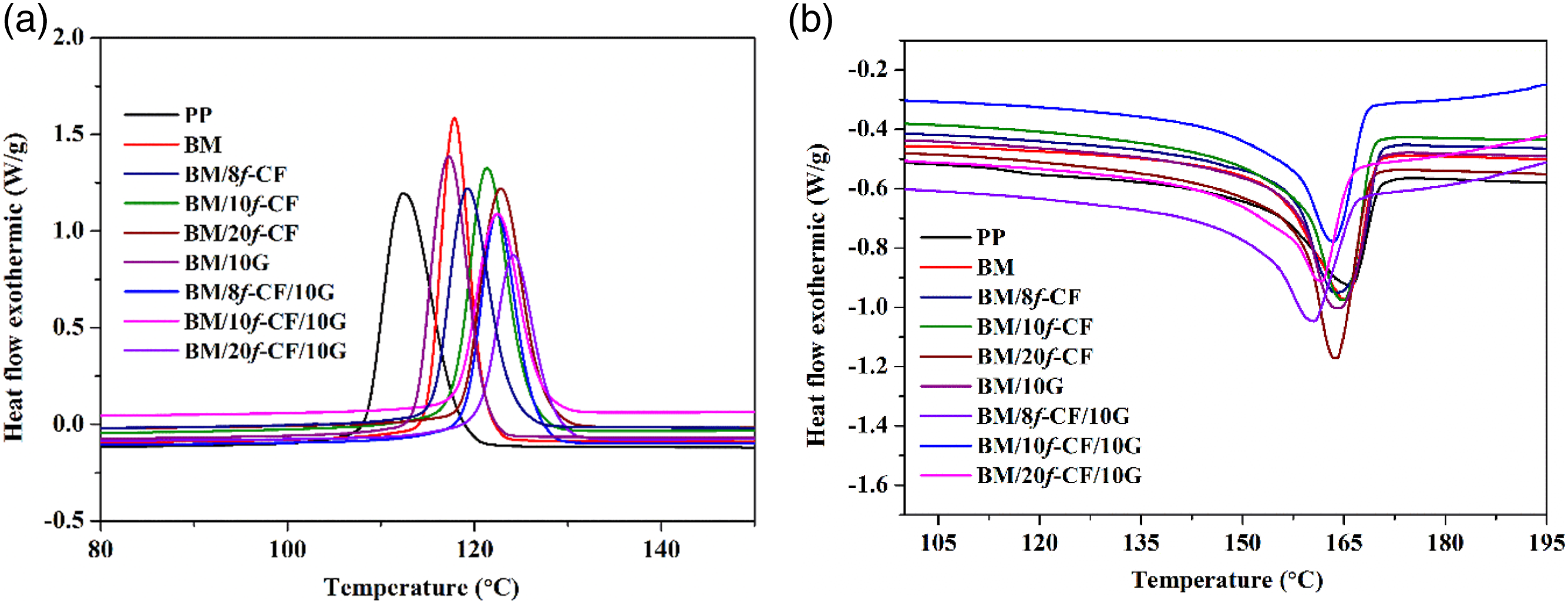
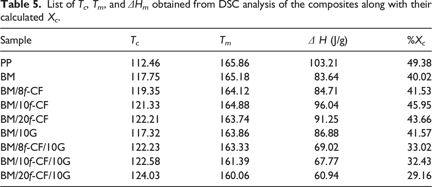
The incorporation of fiber and fillers affected the polymer chain regularity of PP, and hence, a variation in %X c was observed. PP showed %X c of 49.38 which reduced to 40.02 for BM upon incorporation of MA-g-SEBS due to its low inherent crystallinity. Compared to PP, %X c of all the composites reduced significantly. In case of the composites reinforced separately with either f-CF or HGM, the %X c was relatively higher than BM which was probably due to the heterogeneous nucleation initiated around the surface of inclusions. 50 Hybrid composites (BM/8f-CF/10G, BM/10f-CF/10G, and BM/20f-CF/10G) showed a further reduction in %X c due to the increasing amorphous phase brought in by the hybrid inclusions and its increasing wt.%.
XRD
X-ray diffraction analysis of PP and its composites was carried out to explore any changes in their crystal structures. Figure 10 shows the illustration of the diffraction peaks obtained for the composites. Peak’s characteristic of the α phase of PP were observed at 2θ = 14.06°, 16.88°, 18.62°, 21.28°, and 21.86° which correspond to the (110), (040), (130), (111), and (041)/( Diffraction pattern obtained from XRD analysis for the composite samples.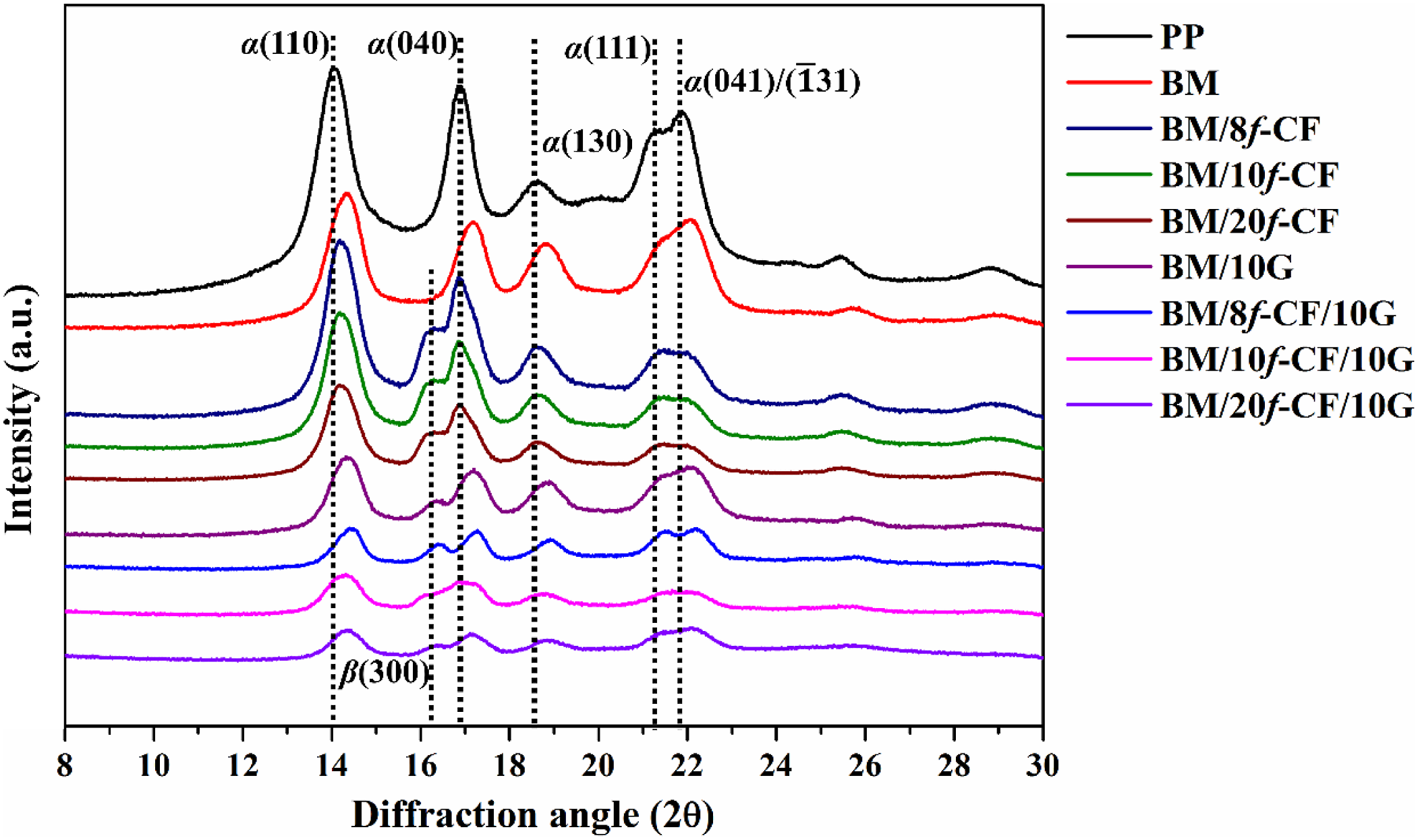
Addition of MA-g-SEBS reduced the overall crystallinity of the BM due to the hindrance in the chain mobility and also due to its own lowered crystallinity. 57 Similarly, the addition of f-CF and HGM separately or in combination reduced the intensities of the crystalline peaks of the composites. The decreasing crystalline peaks for the composites confirm the reduction in %X c value earlier observed in the DSC analysis. Noticeable new crystalline peaks at 2θ ≈ 16.2° correspond to the (300) plane of β form crystal as observed in Figure 10 for the composites. Such peaks appeared due to the hypothesized heterogeneous nucleation around the f-CF (containing CNTs) and HGM filler particles. Similar observations were earlier made for PP composites reinforced with hybrid filler system like functional silica, lignin, 58 bamboo fiber, 59 CNT, 18 CF 50 etc. Lu et al. 60 have earlier stated CNTs to be excellent nucleating agents for isotactic PP and also demonstrated the formation of highly oriented transcrystalline layer around them. Nonetheless, with increasing wt.% of inclusions, amorphous nature of the composites was more evident due to hindrance created by the fibers and fillers in formation of the regular crystal structures.
Conclusion
In the present study, surface modified hierarchical CFs, namely f-CF were prepared by physical and chemical treatments involving u-EPD of CNTs. The f-CFs were used to successfully fabricate light-weight and high strength hybrid PP composites using silane treated HGMs as filler and MA-g-SEBS as compatibilizer. The presence of amine terminated silane groups along with uniform NH2-CNT coating over the f-CF surface led to the formation of cyclic imide bonds among amine functional groups and maleic anhydride groups of MA-g-SEBS, which was confirmed by ATR-IR analysis. In addition, the coated NH2-CNTs were envisaged to form strong physical bonds with the base polymer by mechanical anchoring. The effect of such chemical bonding and mechanical anchoring may have probably enhanced the fiber-matrix interfacial adhesion which was evident from the improved mechanical properties of the composites compared to their pristine counterpart and previously reported PP composites reinforced with different surface modified CFs. Use of silane treated HGM fillers for the hybrid composites not only reduced the bulk density but also improved the processability of the composites by reducing their melt viscosity due to their ball-bearing effect. Significant improvement in the specific tensile properties was observed for hybrid composites as evident in the Ashby plot, which also reflects achievement of desirable properties of the prepared composites for high performance light-weight applications. Morphological analysis of f-CF displayed the successful uniform coating of NH2-CNT by u-EPD and the confirmed good wetting of both the f-CF and HGM by the base polymer matrix in composites. The percentage crystallinity of the composites reduced upon increasing filler inclusions and β crystal formation was evident in the XRD plot due to the nucleation near the surface of inclusions.
Supplemental Material
Supplemental Material - Development and characterization of surface functionalized hierarchical carbon fiber reinforced hybrid polypropylene composites
Supplemental Material for Development and characterization of surface functionalized hierarchical carbon fiber reinforced hybrid polypropylene composites by Rupam Gogoi and Gaurav Manik in Journal of Thermoplastic Composite Materials
Footnotes
Acknowledgements
The first author is grateful to the Ministry of Human Resource Development (MHRD), Government of India for the financial support provided in the form of monthly stipend.
Declaration of Conflicting Interests
The author(s) declared no potential conflicts of interest with respect to the research, authorship, and/or publication of this article.
Funding
The author(s) received no financial support for the research, authorship, and/or publication of this article.
Supplemental Material
Supplemental material for this article is available online.
References
Supplementary Material
Please find the following supplemental material available below.
For Open Access articles published under a Creative Commons License, all supplemental material carries the same license as the article it is associated with.
For non-Open Access articles published, all supplemental material carries a non-exclusive license, and permission requests for re-use of supplemental material or any part of supplemental material shall be sent directly to the copyright owner as specified in the copyright notice associated with the article.