
Abstract
This article proposed a new convenient method to obtain tear strength of an airship envelope fabric, which is a laminated plain weave fabric with the ultra-high molecular weight polyethylene fibers. First, a modified formula based on Maekawa’s empirical formula was derived. Uniaxial tear tests were then conducted on three series of single-edge notched specimens with varying widths and their critical tear stresses were measured. The experimental result showed that critical tear stress decreases with the reduction of specimen width when initial crack length is fixed. Afterward, the tear stresses of the fabric were simulated by Maekawa’s empirical formula, the modified formula, and Thiele formula. By comparing the theoretical results with the experimental results, the modified formula was verified to be consistent well with the test data. Finally, an equation was derived, which shows tear strength of this fabric decreases as initial crack length increases. For instance, when the initial crack length is 31.75 mm, the tear strength is only 44.52% of the tensile strength.
Introduction
Stratospheric airships (SSAs) are controllable lighter-than-air (LTA) aircrafts. SSA can stay in the stratosphere for several months or even years on buoyancy of hydrogen or helium contained in their envelopes. The envelopes must exhibit low gas permeability, high environmental resistance, high strength-to-weight ratio, and excellent tear resistance. 1 To meet these requirements, envelopes are generally made of high-strength coated or laminated fabrics and they have attracted widespread attentions.
Most common failures of the fabrics are caused by tear propagation, which generally begins from a flaw or a tiny crack. 2 For an airship, a crack may lead to critical fracture of its envelope and even collapse of the whole airship. To avoid the accident, it is crucial to investigate tear properties of airship envelopes.
Numerous tear test methods for fabrics have been proposed, such as tongue, 3 trapezoid, 4 central crack, 5 and pressurized cylinder tear test. 6 Thereinto, pressurized cylinder tear test is the most appropriate method to study tear properties of airship envelopes since they are similar in shape. Topping, first manufactured inflatable cylinders and investigated the relation of tear strength to initial crack length. Referring to Topping’s work, Thiele 7 then conducted tear test on two cylinders of an airship envelope material. According to the test results, he derived a formula to describe the relationship between tear strength and crack length. Afterward, Maekawa et al. 8 carried out a similar test on a cylinder measured 4000 mm in length and 900 mm in diameter (Figure 1) and the initial crack lengths range from 70 to 200 mm. He proposed a new empirical formula to demonstrate the relationship between tear strength and initial crack length. However, the influence of cylinder lengths on tear strengths of the fabrics was ignored in their formulas because cylinder lengths are so larger than the crack lengths that cylinder lengths would not affect their tear strengths.
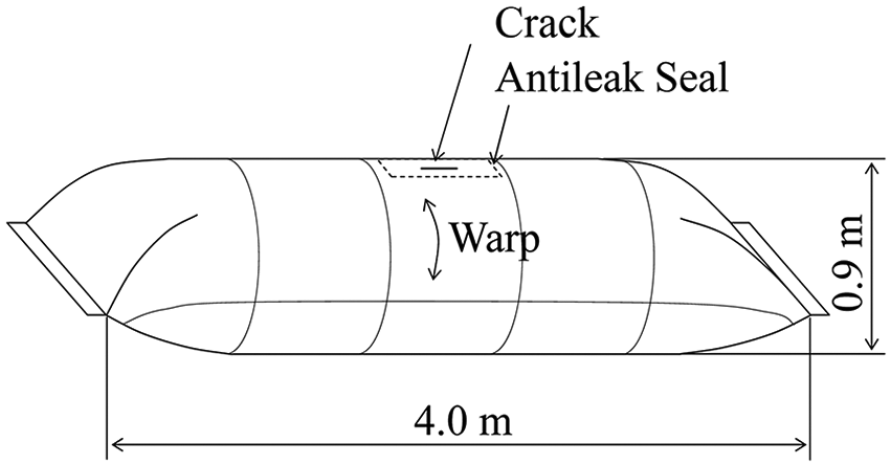
Pressurized cylinder tear test for airship envelope. 8
Compared to pressurized cylinder tear test, uniaxial central crack tear test is more widely used because of its convenience and low cost. Meanwhile, according to the previous study, 9 central crack tear test can also better simulate the crack propagation of a damaged inflatable airship envelope compared to tongue and trapezoid tear tests. This tear test was developed and utilized by US Navy in the 1950s. 10 Federal Aviation Administration 5 (FAA) then adopted this test method in FAA-P-8110-2 (Figure 2(a)). In recent years, Chen et al. 11 conducted tear test on Uretek-3216LV envelope fabrics. The dimensions of the specimens used in his test are the same as those of FAA’s specimens, as shown in Figure 2(b). The crack lengths of the specimens in Chen’s test ranged from 10 to 30 mm instead of the fixed crack length 31.75 mm in FAA-P-8110-2. Besides, as shown in Figure 2(a) and (b), the clamped regions between their tests were quite different, which surely affected the stress distribution near the crack tip. Hence, the critical tear forces were different when the cracks began to propagate. Moreover, the difference between the sizes of a uniaxial central crack specimen and a cylinder would lead to different test results.
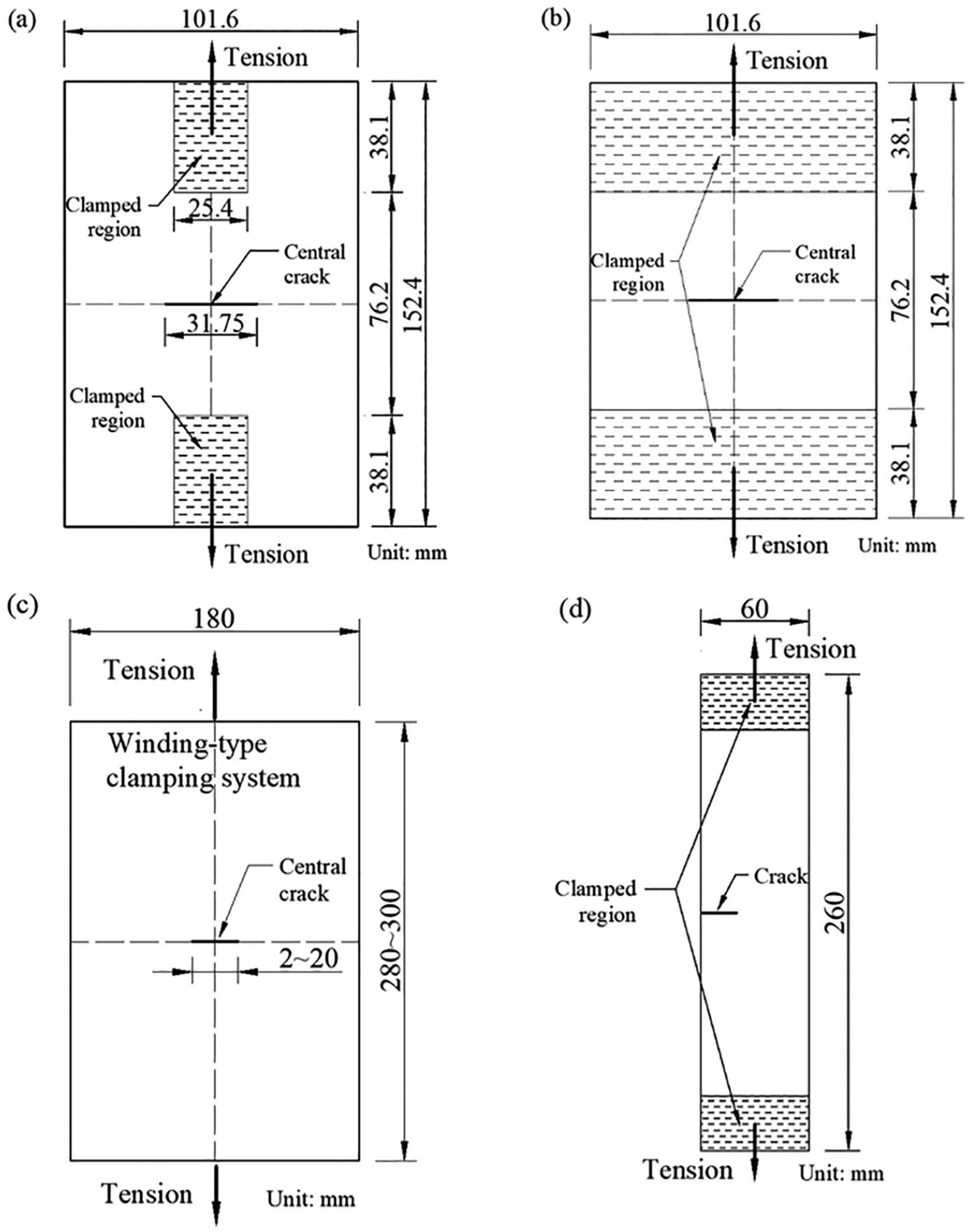
In 1978, Minami 12 had already noticed the influence of specimen size on tear strength. In order to minimize the influence, he set the specimen length at 300 mm, the width at about 180 mm, and the crack lengths varying from 2 to 20 mm (Figure 2(c)). Then, many researchers conducted this kind of tear test on airship envelope fabrics or architectural membranes.13–16 However, some smaller specimens were also tested in some literatures,14–16 of which the dimensions were just about 300 mm × 50 mm. These specimens may be too small to obtain their tear strengths. In addition, uniaxial tear test on single-edge notched (SEN) specimens was recently conducted by some researchers (Figure 2(d)).17–19 SEN specimens can approximately be on behalf of uniaxial central crack specimens and this test is more convenient and economical to perform than pressurized cylinder tear test. Therefore, SEN specimens were used in this article.
Otherwise, many researchers have analyzed tear strengths of fabrics theoretically. For instance, Hedgepeth and colleagues20,21 proposed the first micromechanical analytical model of a damaged filamentary structure and found the static stress concentration factors in unbroken filaments. Godfrey et al.22,23 presented a micromechanical model to predict the onset of tearing at slits in biaxially stressed uncoated and coated plain weave fabrics. Analytical results obtained for the model exhibits good agreement with experimental results.
As shown in Figure 2, the sizes of the specimens used by FAA, 5 Chen et al., 11 and Liu et al. 17 may be too small. The sizes cannot be assumed to be infinity compared to crack lengths. Generally, tear stress of a specimen of a fabric would be less than tear strength of the fabric if the specimen size is insufficient compared to its crack length. Therefore, the measured tear stresses may not be the tear strengths of the tested fabrics.
Even though, this article proposed a new method to obtain tear strength of a fabric by conducting uniaxial tear test on SEN specimens. First of all, the influence of specimen width on tear strength was investigated theoretically. Specimen width was introduced into Maekawa’s empirical formula (MEF), 8 and a modified formula was derived. Uniaxial tear tests were then conducted. Three series of SEN specimens with different widths were fabricated and crack lengths varied in each series. The critical tear stresses of specimens were measured when cracks began to propagate. According to the experimental results, a parameter Bm representing tear property of a fabric was calculated from the modified Maekawa’s empirical formula (MMEF). The relationship of the tear strength of this fabric and initial crack length was then worked out and theoretical results of formulas were also compared with test data. Eventually, the tear strength of the fabric was calculated.
Theoretical method
MEF
The empirical formula was based on the following three assumptions:
The specimen size is large enough that the stress in the boundary is unaffected by the crack (shown in Figure 3).
The load within the crack region is distributed exponentially as a stress concentration outside the crack region.
The crack starts to propagate when the fiber stress at the crack tip reaches the ultimate strength of the envelope material,

Stress field near the crack tip of a wide specimen.
Then, the MEF is derived as

Here,

Here, N is the number of specimens.
MMEF
For a narrow specimen in uniaxial tear tests, shown in Figure 4, the stress in the boundary would be affected by the crack. Thus, the first assumption is no longer suitable. Then, the width of specimen was introduced into MEF to derive a new formula.

Stress field near the crack tip of a narrow specimen.
The stress is still assumed to distribute exponentially near the crack. Therefore
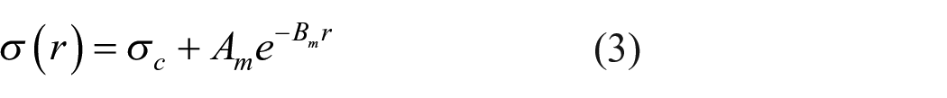
Here, Am and Bm are constants, r is the distance from the crack tip to a position along unloading direction and the stress at the position is
The total force F of a specimen with an initial crack would be written as

Here, b is half a specimen width.
Meanwhile, the external force can be expressed as

Hence, the force equilibrium equation is

Therefore

According to the third assumption, the following relation can be introduced from equation (3)

From equations (7) and (8), the MMEF is obtained as

Obviously, as b approaches infinity, MMEF’s and MEF’s calculating results are identical.
Similarly, the value of Bm can also be found through a trial and error process by applying the test data into equation (10)

If the specimen’s width is large enough, equation (9) can be changed into equation (1).
Experiment
Uniaxial tear tests on three series of SEN specimens were conducted in this section. The material, a new SSA envelope, was first introduced. Experimental processes and results were described and analyzed, thoroughly.
Material
The material tested in this work is a laminated plain weave fabric including three layers: the structural layer, the gas retention layer, and the environmental layer, as shown in Figure 5(a). Each of the layers have different functions. The structural layer is weaved by the ultra-high molecular weight polyethylene (UHMW-PE) fibers. The fiber owns a high strength, high modulus, light resistance, and resistance to heat aging. 24 Hundreds of fibers make up a single yarn. And, there are nine yarns per centimeter in both warp and weft directions in the structural layer. The gas retention layer is made from ethylene vinyl to prevent gas leakage. The protective layer is made from alcohol polymer that can protect the other layers from ultraviolet, visible radiation,and so on. 25 Those three layers are glued with polyurethane. The areal density of the fabric is only 170 g/m2 with a thickness of 264 μm.

The airship envelope: (a) the layers of the fabric and (b) the fabric.
Experimental process
Single-yarn specimens and SEN specimens were fabricated. As shown in Figure 6(a), all the specimens are 300 mm. There are three categories of SEN specimens with different widths (shown in Figure 6(b)). Integer numbers of fiber bundles were cut in all SEN specimens. If the initial crack was introduced by the unit of centimeter, it would be inevitable to cut a portion of one fiber bundle in some cases.
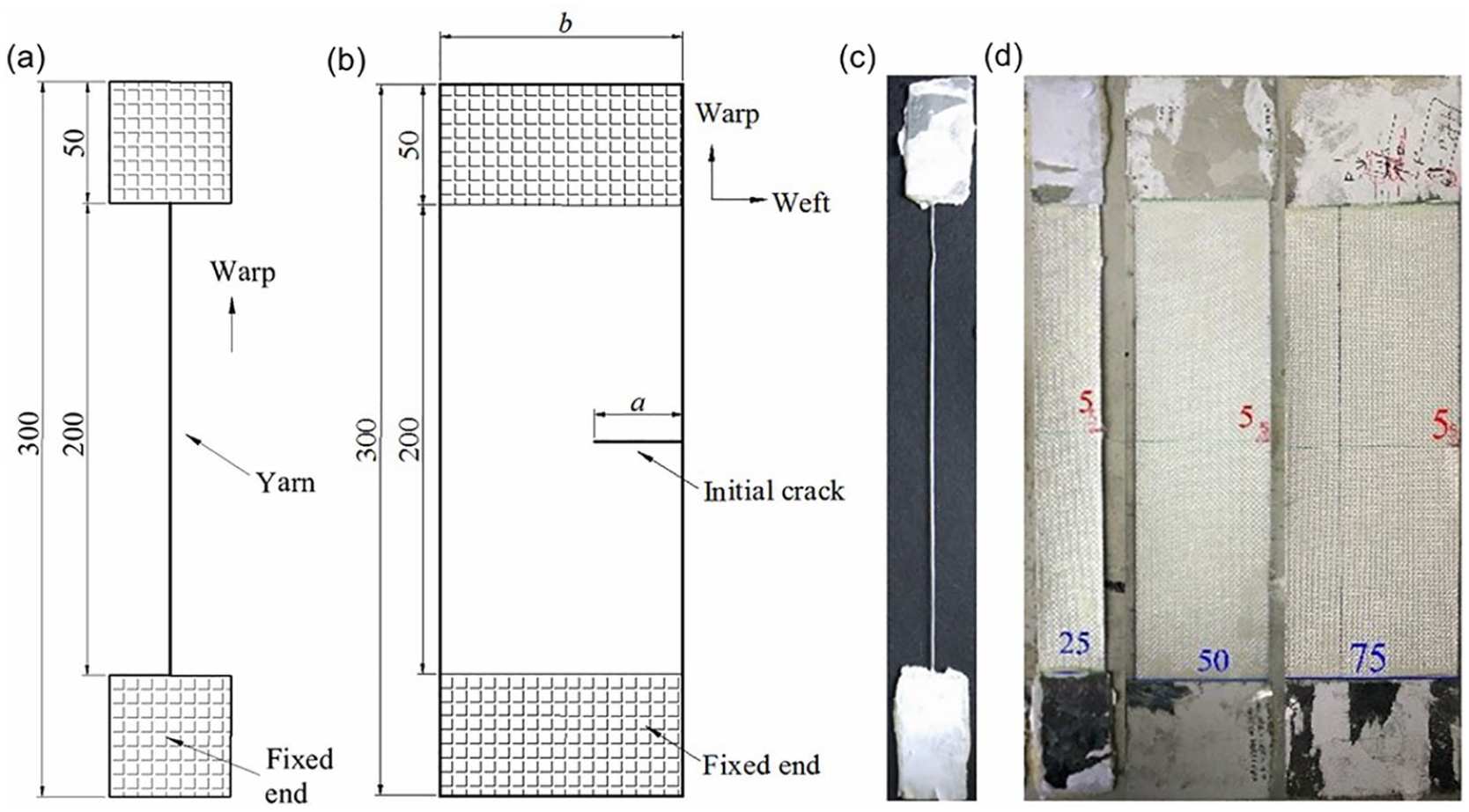
Geometry of specimens: (a) and (c) single-yarn specimens. (b) and (d) SEN specimens.
The specification of all categories of specimens was summarized in Table 1. As shown in Table 1, single-yarn specimens and SEN specimens were, respectively, named as Y and T-n-m. The n and m represented the total number of warp yarns of SEN specimens and the number of the cut yarns, respectively. For each category of SEN specimen, the largest initial crack length ratio m/n was set to 0.6, according to Liu et al’s. 17 work. Besides, thin aluminum sheets were pasted on both sides of each specimen’s ends to avoid the specimen slipping off the clamp during testing.
Specification of all specimens.

All the experiments were carried out on an electronic universal testing machine (UTM4000), shown in Figure 7. A 5 N pre-tension was initially applied to each specimen to check whether the warp yarns are parallel to the load direction. The tensile speed was set to be 10 mm/min. Crack propagation was recorded by a digital camera. According to the ISO 139-2005 standard, a climatic room temperature of 20°C ± 2°C and a relative humidity of 65% ± 4% were ensured during testing.

Tensile and tear test of specimens: (a) uniaxial tensile test of a yarn and (b) tear test of a SEN specimen.
Experimental results
The crack propagation process of such envelope fabric is shown in Figure 8. First, as tensile load increased, the crack gradually opened and warped out of the plane (Figure 8(a)). A del-zone then appeared at the crack tip and gradually expanded (Figure 8(b)). As the del-zone expanded, the gas retention layer and environmental layer were torn along the crack. The warp yarns in the del-zone became slim because of stress concentration at the crack tip. When the stress of the first warp yarn at the crack tip reached its ultimate tensile strength, the yarn fractured brutally and the crack began to propagate (Figure 8(c)). At the same time, the tensile stress of the specimen declined slightly and a peak stress appeared in the stress–strain curve for the first time (shown in Figure 9(b) to (d)). The first peak stress of each curve was defined as the critical tear stress. Then, as the tensile load increased, the tensile stress rose slightly. After a while, the second warp yarn fractured and a new peak stress appeared. As warp yarns fractured one by one, a series of peak stresses appeared until the tensile stress fell suddenly and the specimen fractured completely. The failure can be described as progressive.

Tearing propagation of a crack: (a) the opening of a crack; (b) the appearance of a del-zone; and (c) the propagation of a crack.

Stress–displacement curves of specimens: (a) Yarns; (b) T-25-m; (c) T-50-m; and (d) T-75-m.
All the stress–displacement curves of the T-25-m specimens are shown in Figure 9(b). While, in order to exhibit the curves of T-50-m and T-75-m specimens clearly, one curve in each case is plotted in Figure 9(c) and (d). Meanwhile, the first peak stresses of the curves are marked by short arrows. As shown in the curves, the first peak stresses of these specimens are not always their maximum stresses, which may be affected by the number of uncut fiber bundles. For example, the specimens, T-25-m and T-50-30, whose critical stresses are their maximum stresses, own not more than 20 uncut fiber bundles; the remaining uncut yarns cannot bear the maximum force after the first yarns of these specimens at crack tip fractured. In contrast, the least number of uncut fiber bundles of all the other SEN specimens is 25 and their critical stresses are lower than their maximum stresses.
As shown in Figure 10(a), the failure modes of single-yarn specimens and SEN specimens are different. The failure of single-yarn specimens occurred suddenly, and it can be described as brutal; but, the failure of SEN specimens occurred gradually. Hence, this failure can be described as progressive. Moreover, for the SEN specimens, the cracks propagated along the weft direction. It could be visible that the surfaces of specimens became coarse due to the fracture of warp yarns.

The failure of specimens: (a) the single-yarn specimens and (b) the T-75-m specimens.
Then, all the critical tear stresses and the standard deviations were specified in Table 2. Specifically, the stress is defined as force per unit width, which is generally used in membrane structures.
Critical tear stresses of all specimens.

The variations of the critical tear stress with specimen width and initial crack length are shown in Figures 11 and 12. When the initial crack lengths are identical, the critical tear stress of such fabric increases by increasing specimen width. For example, the critical tear stress of T-50-5 (65.60 N/mm) is higher than T-25-5 (58.28 N/mm). It is because that the wide specimens have more remaining uncut yarns to share the load from the crack region. Hence, the stress concentration factors at the crack tip in the wide specimens are smaller than those of the narrows. This shows that specimen width has significant effects on the critical tear stresses of SEN specimens.

Critical tear stress varying with specimen width.

Critical tear stress varying with initial crack length.
However, when specimens’ width is fixed, the critical tear stress decreases as initial crack length increasing (Figure 12). For example, the critical tear stress of T-50-30 (26.41 N/mm) is lower than T-50-15 (40.42 N/mm). The longer a crack is, the less damaged yarns were left to bear tensile load. Moreover, the wide specimen’s critical tear stress decreases more slowly than the narrow specimen. This also means that specimen width affects the critical tear stresses of SEN specimens.
Discussion
Comparison of test data and theoretical results
Thiele empirical formula (TEF) was cited by many researchers. Hence, it was utilized here to compare with MEF and MMEF.
According to the thesis, 26 for a plane specimen, TEF was simplified into
Here,


Then, Ck and n are calculated; they are 179.91 and 0.4256, respectively. TEF for the airship envelope fabric is

However, by applying all the test data into equations (2) and (10), the values of B and Bm are 0.05444 and 0.03926, respectively.
According to equations (1) and (9), MEF can be obtained as
and MMEF is obtained as

To make a clear comparison between theoretical results and the test data, the results are shown in Figure 13.

Comparison of the theoretical results with test results.
According to equations (12) and (13),

Tear strength of the fabric.
Tear strength
To obtain the tear strength of the fabric, the width of it should be assumed to be infinite and b approaches infinity. Equation (14) is then derived into

The comparison of tear strengths with critical tear stresses is shown in Figure 14. Finally, tear strength of the fabric can be calculated using equation (15). For example, when the initial crack length is 31.75 mm same as the crack length in FAA, the tear strength is 36.32 N/mm, 44.52% of the tensile strength.
Conclusion
In this article, a new convenient method was proposed to obtain tear strength of an airship envelope fabric. Based on the theoretical and experimental study, the following conclusions can be drawn:
Specimen width has much significant impact on critical tear stresses of SEN specimens. Specifically, when initial crack length is fixed, critical tear stress would increase as specimen width becomes larger. Critical tear stress decreases with the increasing of initial crack length. Moreover, the wide specimen’s critical tear stress decreases more slowly than the narrow specimen’s critical tear stress.
After specimen width was taken into account, the results of MMEF are much more consistent well with the test data than those of MEF and TEF. Specially, only the results of MMEF agree with the critical tear stresses of T-25-m. Besides, when the initial crack length is smaller than 5.56 mm, the results of TEF are much higher than other results due to the ignorance of tensile strength of the fabric.
A constant Bm, which characterizes tear strength of a fabric, can be calculated using MMEF and critical tear stresses measured in uniaxial tear test. The Bm of the fabric investigated in this article was 0.03926. Finally, a formula was derived to describe the relationship of tear strength and initial crack length of this fabric. When the initial crack length is 31.75 mm, the tear strength is 36.32 N/mm.
Footnotes
Declaration of conflicting interests
The author(s) declared no potential conflicts of interest with respect to the research, authorship, and/or publication of this article.
Funding
The author(s) received no financial support for the research, authorship, and/or publication of this article.