
Abstract
The concrete-faced rockfill dam valley foundation was considered as an open energy system and a reasonable non-uniform seismic motion input method was applied to the dynamic analysis of a concrete-faced rockfill dam based on the generalized plastic model. First, the corresponding program was validated by means of the scattering question of an idealized semicircle valley. Subsequently, the seismic elasto-plastic finite element analyses were performed to compare and investigate the performances of a concrete-faced rockfill dam under different seismic motion input methods. The results show that the dynamic responses of the concrete-faced rockfill dam are decreased by 10%–30% approximately with the use of non-uniform seismic motion input method. As a result, the traditional uniform seismic motion input method would overestimate the responses of the dam. From the perspective of seismic safety evaluation, the overestimations would disturb the reasonable assessment of the aseismic capacity of the dam. Moreover, the slope stability analysis results might be conservative and unreasonable due to overestimating the accelerations during the earthquake.
Keywords
Introduction
Concrete-faced rockfill dam (CFRD) is a type of embankment dam that is being widely used and rapidly developed. Several CFRDs over 200 m in height are being built or to be built in China’s strong seismic regions, such as Houziyan, Gushui, and Lawa. Since the dam failures due to strong earthquakes will cause catastrophic consequences, the safety of these CFRDs during earthquake is an important engineering and social problem and has been well recognized.1,2 Numerical analysis of CFRDs during strong motion is an effective method to evaluate the seismic safety and has been investigated by many researchers.3–6 Although some sophisticated numerical methods have been developed for seismic analysis of high dams, it is still immature in studying realistic earthquake behavior of a complete CFRD valley foundation system especially involving nonlinearities of rockfill and foundation materials. Generally, the fixed boundary and uniform seismic motion input (USMI) method proposed by Clough 7 were adopted in most of the studies, which means CFRDs were fixed on the shaking table (the same ground motion acts simultaneously). The foundation flexibility can be considered in this method but the interaction between CFRD and foundation was not appropriate. In addition, with the increase in dam height, the dam axial length even over 1000 m, the wave propagation effect is obvious in the dam body. It is well known that the CFRD valley foundation is an open energy system, so the different interaction between them and the wave radiation effects due to infinite foundation during earthquake should be considered. Therefore, the reasonable safety evaluation of CFRDs has to be researched through non-uniform seismic motion input (NUSMI) method. 8
To cover the limit of the USMI method, various artificial boundaries and corresponding seismic motion input method9–16 have been investigated. The essence of the artificial boundary is to allow scattered wave from the generalized structure through the truncated foundation boundaries toward infinite domain without reflecting. The typical artificial boundaries include transmitting boundary, 11 absorbing boundary, 12 viscous boundary, 13 and viscous-spring boundary.14,15 Viscous-spring artificial boundary has been applied in dynamic response of underground structure, 16 arch dam,17–19 earth and rockfill dam, 20 and so on. Zhao et al. 16 found that the result of the method has high precision compared with analytical result, and this method was used in dynamic analysis of a cross-river shield tunnel. Zhang et al. 19 developed the artificial boundary and investigated the arch dam–canyon interaction, and the results showed that the use of viscous-spring boundary model leads to about 25%–40% reduction in dynamic response of the arch dam. Zhou et al. 20 investigated the effects of the method on the interaction between earth-core rockfill dam and foundation based on equivalent linear model (Hardin–Drnevich model). However, this method has rarely been used in CFRDs especially based on the generalized plastic model. Reasonable dynamic analysis results are particularly important for assessing the dam safety, including the slope stability, the foundation liquefaction, the slab damage, and the aseismic measures design. So, in this study, on the basis of the generalized plastic model 21 for the rockfill materials, the generalized plastic interface model 22 and element with asymmetric nodes 23 between slab and cushion layer contact surface established by the authors, the plastic damage constitutive model for concrete proposed by Lee and Fenves, 24 the viscous-spring boundary, and the corresponding NUSMI method 15 are used by the authors. Numerical verification of scattering question of an idealized semicircle valley is performed. Subsequently, for comparing effects of different seismic motion input methods on the CFRDs’ dynamic responses, including the dam acceleration, concrete face slab damage development, and distribution and the permanent deformation, a series of seismic analyses of the CFRDs constructed on the bedrock are performed through two-dimensional (2D) finite element numerical analysis. Finally, some conclusions are given.
NUSMI method
Viscous-spring artificial boundary
Based on the assumption that the scattering wave could be regarded as 2D cylindrical wave and three-dimensional (3D) spherical wave, the 2D and 3D viscous-spring artificial boundary was proposed by Liu and Lu. 15 As illustrated in Figure 1, the viscous-spring artificial boundary can be approximately equivalent as parallel spring–dashpot system installing on the cut-off model boundary. This boundary is efficient and convenient for finite element procedure with satisfied accuracy and is used herein. The spring coefficient K and viscous dashpots coefficient C can be calculated as follows 14
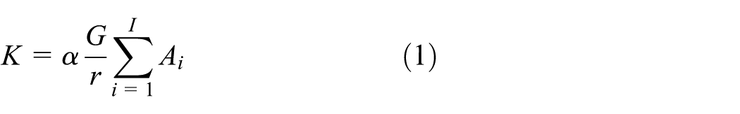

where ρ and G are the medium mass density and shear modulus, respectively. r is the distance from the scattering source to the artificial boundary. For normal direction and tangential direction boundary, c, respectively, denotes the velocity of P wave and S wave.

Viscous-spring artificial boundary.
On the basis of viscous-spring artificial boundary, the authors developed a type of element (viscous-spring boundary element (VSBE)) to substitute the traditional concentrated viscous-spring artificial boundary. The VSBE is an interface element with spring and damping as illustrated in Figure 2. The spring and dashpot’s parameters are calculated by equations (1) and (2). Compared with the traditional concentrated viscous-spring artificial boundary, in which two or three boundary elements should be added to perform 2D or 3D analysis, only one boundary element is needed using VSBE.
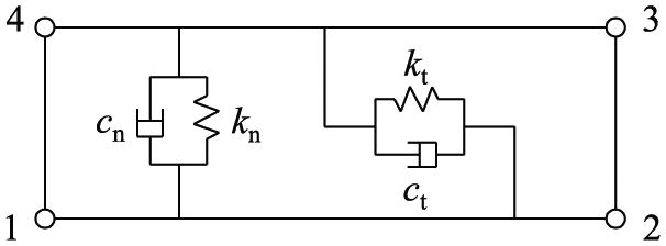
Viscous-spring interface element.
The equivalent nodal load
Different from the USMI method, amplitudes and phases of earthquake are different along boundary. 15 Viscoelastic artificial boundary can be easily combined with finite element mesh in NUSMI method. The VSBE is used by spring and damping belongs to boundary of the model. By the equivalent nodal load on the boundary nodes, it can realize seismic motion input with VSBE. The equivalent nodal load was used to simulate the stress boundary of the actual wave field and it can be calculated as follows 14

where
Scattering question of semicircular valley
The scattering question of semicircular valley under vertical incidence of SV wave is analyzed to validate the accuracy of NUSMI method 15 and the program was developed by the authors.
As illustrated in Figure 3, the incidence angle θ is equal to 0° under wave vertical incidence. The valley radius r0 is equal to 210 m. The mass density of material ρ = 2.65 g/cm3, and the shear modulus G = 5.292 GPa, and Poisson’s ratio υ = 0.33. The height of model yb = 525 m and the width xb = 1050 m. The finite element grid is shown in Figure 4, in which height and width of the outer element both are equal to 17.5 m. The expression of non-dimensional frequency is defined as η = 2r0/λ = ωr0/πcs (0.5 and 2.0 are selected), in which the wavelength λ = 1 m, ω is the circular frequency, and cs is the shear wave velocity.
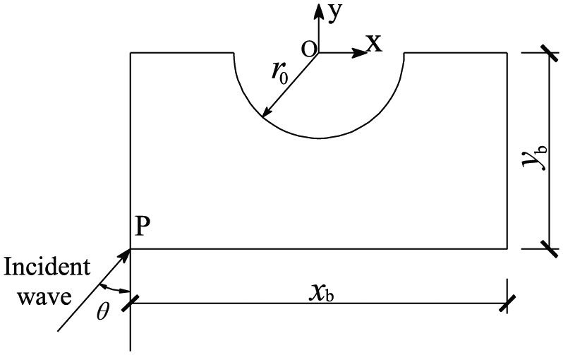
Semicircle valley under wave incidence.
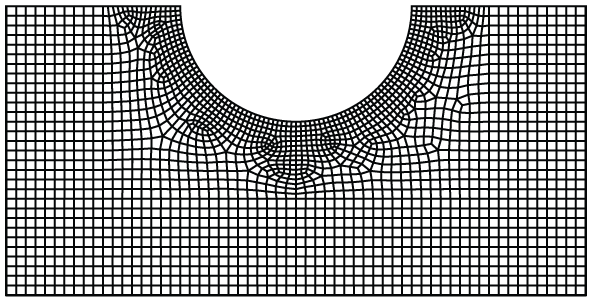
Finite element mesh of semicircle valley.
Due to no analytical solution for benchmark problem, the calculated results are calibrated with the solution using indirect boundary integral method by Wong. 26 The comparisons are illustrated in Figures 5 and 6; it can be seen that the NUSMI input method could be used to simulate the responses of the canyon with the satisfied accuracy.
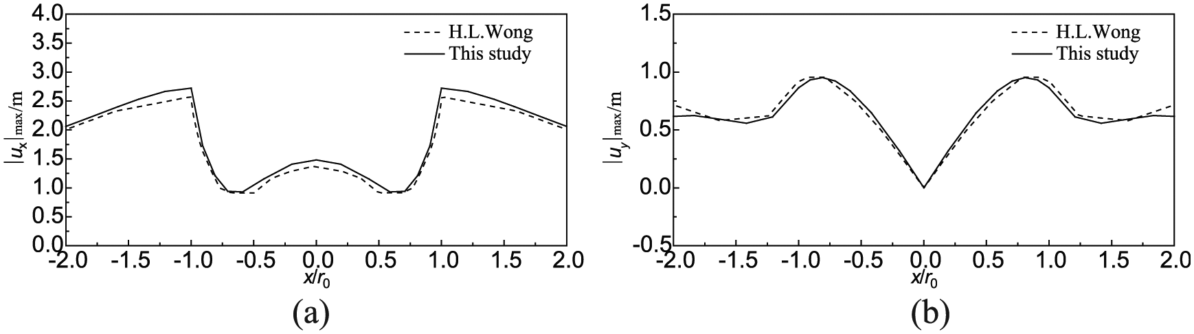
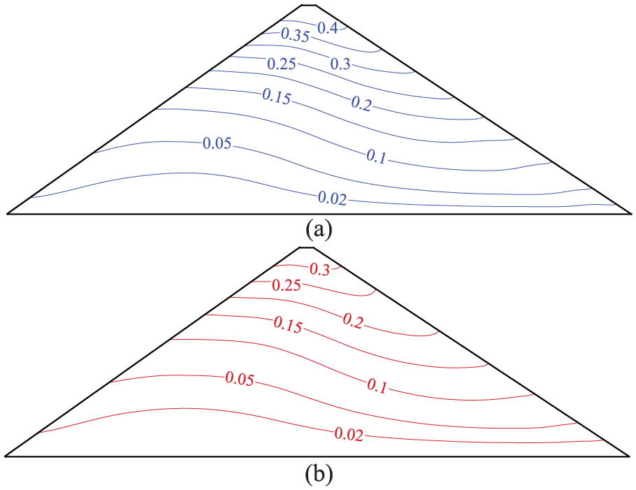
Surface displacement amplitude under SV wave vertical incidence (η = 0.5): (a) horizontal and (b) vertical.
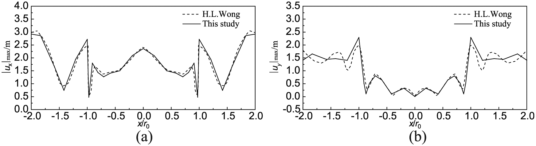
Surface displacement amplitude under SV wave vertical incidence (η = 2.0): (a) horizontal and (b) vertical.
Interface element with asymmetric nodes
To study the dynamic damage of the concrete face slab, the mesh size of the slab should be controlled less than 0.3 m.6,23,27 However, the transition of the finite element mesh from the slab to the cushion layer and rockfill materials would be complex and some irregular mesh will influence the calculation accuracy. Therefore, interface element with asymmetric nodes was applied by the authors to resolve this problem. 23 The interface element contains arbitrary number of nodes and can solve the problem of mesh transition between the slab and the cushion layer. Meanwhile, it has the advantages in modeling and the adaptation of the change of dam zoning. In addition, on the basis of ensuring the accuracy of the calculation, the element can greatly reduce the number of elements and improve the computational efficiency.
The typical interface element with asymmetric nodes is shown in Figure 7. The fine mesh connected to the nodes at the top surface and the coarse mesh connected to the nodes at the bottom surface. In simulation, the interface element is divided into n − 1 sub-elements using the n − 1 virtual nodes placed on the bottom surface that will be finally condensed out, and each sub-element can be regarded as a traditional slip element. The relationship between the displacement vectors


where [T] is a matrix of (4n) × (2n + 4), L is the length of the interface, and i is the node number.

The interface element with asymmetric nodes.
The stiffness matrix of the interface element,

Compared with the interface element with asymmetric nodes with 2 Gauss points and the traditional Goodman element, the results show a good agreement and the maximum difference is less than 1%. It indicated that the accuracy of proposed interface element is acceptable. 23
Finite element analysis of CFRD
The GEODYNA program, 28 which was developed by Institute of Earthquake Engineering, Dalian University of Technology, was adopted for static and dynamic finite element analysis in this study. Using GEODYNA, the dynamic responses were investigated by the authors.6,20,21,23,27
Finite element model
A 2D CFRD with a height of 200 m is used as the finite element model. The upstream slope is 1:1.4, and the downstream slope is 1:1.5. The dam was filled in 114 layers, and the concrete face slab was constructed in three stages (the slab top heights of each stage are 60, 130, and 200 m, respectively). The water level is 190 m, and impoundment begins after the completion of second stage of face slab pouring.
The finite element mesh of the CFRD is shown in Figure 8; the detailed mesh view of the concrete face slab, cushion layer, transition layer, and interface elements is shown in Figure 8. Seven “observation points,” as shown in Figure 9, were chosen to compare the dynamic responses due to different seismic motion input methods. The concrete face slab is divided into five layers along the normal direction; the largest element size is 20 cm, for the convenience of studying the damage development process. The slab element uses 4-node isoparametric elements and the contact surface between the slab and cushion layer uses asymmetric 19-node interface element. The model contains 18,636 elements and 20,472 nodes in total, including 8960 slab elements.

The finite element mesh of the concrete-faced rockfill dam.

The detailed mesh view of the concrete face slab, cushion layer, transition layer, and interface elements.
The dynamic water pressure on face slabs was considered by added mass element during earthquake. The added mass element was defined on the nodes outside of the face slabs. The added mass intensity can be calculated by “Specifications for seismic design of hydraulic structures” (DL 5073-2000). 29
Material parameters
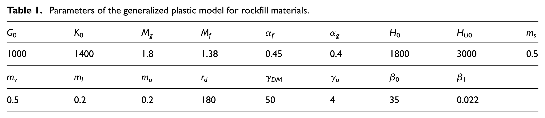
The generalized plasticity model parameters for rockfill materials 21 are listed in Table 1. The contact surface between the concrete face slab and the cushion layer uses a generalized plasticity interface model, and the computational parameters 23 are listed in Table 2. The plastic damage model proposed by Lee and Fenves 24 was used to simulate the concrete face slab. The property parameters used in the analysis are provided in Table 3. Because the compressive strength of concrete is considerably higher than the tensile strength, only the tensile damage of the slab concrete is considered in this study. The bedrock material has the following parameters: elastic modulus E = 10 GPa, Poisson’s ratio ν = 0.25, mass density ρ = 2450 kg/m3, and damping value = 0.05.
Parameters of the generalized plastic model for rockfill materials.
Parameters of the generalized plastic interface model for contact surface between the concrete face slab and the cushion layer.
Parameters of the plastic damage model for concrete face slab.

Input of seismic motion
The seismic motion input to the mechanical model is based on “Specifications for seismic design of hydraulic structures” (DL 5073-2000) 28 with a specified artificial seismic wave spectrum. The seismic wave history (the acceleration response of outcrop) is shown in Figure 10. The horizontal peak acceleration of seismic waves along the river direction is 0.3 g, and the vertical peak acceleration takes two-thirds of that along the river direction. Acceleration amplification response spectra of the standard design and the input of seismic motion are shown in Figure 11.

The acceleration history of outcrop: (a) horizontal direction and (b) vertical direction.

The acceleration amplification response spectrum.
Analysis of computational results
The step-by-step construction of the dam was simulated first in the analysis. The initial stresses induced in the concrete face slab and dam body during water impounding are also considered in the analysis and are subsequently applied for the seismic analysis. The dynamic responses of the CFRD were analyzed by two different seismic motion input methods. In case 1, the USMI method was used with massless foundation and the NUSMI method was used with mass of foundation in case 2. In case 1, the massless foundation model is assumed that the bedrock is linear elastic and massless. The boundary of the bedrock is fixed and the seismic inertia force is applied to the dam body, so that seismic loads along the boundary are the same. The same finite element mesh was used for the two cases except boundary element. In this way, the calculated results by different seismic motion input methods could be compared reasonably.
The dam body acceleration responses
Figure 12 illustrates the acceleration response history of the points A, B, and C at the points on dam axis of different elevation during 10–15 s. The maximum acceleration responses along the dam axis are shown in Figure 13. It can be seen that the acceleration histories are similar tendency by different input methods under wave vertical incidence, and the peak value by NUSMI method decreased about 10%–25% and postponed, which indicated that the NUSMI method could reflect the radiation damping and the wave propagation effect in the bedrock and dam body.

The acceleration responses history of observation points in dam body: (a) point A, (b) point B, and (c) point C.

The maximum acceleration responses along the dam axis.
The dam deformation
In Figure 14, the settlement histories of “observation point” E located at the dam crest calculated by different seismic motion input methods are shown. The maximum settlement of point E calculated by the NUSMI method decreases 18% compared with that by the USMI method. Figures 15 and 16 illustrate the contours of the horizontal and vertical permanent deformation in the dam body at the end of earthquake. It can be seen that the horizontal and vertical permanent deformation to the downstream direction by the NUSMI method is significant lower (about 20%) than that by the USMI method. It can be concluded that due to the radiation damping of infinite foundation, the lower dam deformation in both horizontal and vertical directions will be expected in the dam body.

The settlement history of point E by different seismic motion input methods.
The horizontal permanent deformation in the dam (unit: m): (a) USMI and (b) NUSMI.

The vertical permanent deformation in the dam (unit: m): (a) USMI and (b) NUSMI.
The stress and damage in the slab
Two typical slab elements (damage occurred and without damage) and stress histories along the slope direction during the earthquake are depicted in Figure 17. The maximum stresses along the slope direction in the middle layer slab by different seismic motion input methods are compared in Figure 18. It can be seen that the tensile and compressive stress tendencies by the two different seismic motion input methods are similar under wave vertical incidence, but the tensile damage range and the maximum compressive stress are reduced due to the radiation damping when the NUSMI method is implemented. Also, because of the plastic damage model used for the concrete face slab, the maximum tensile stress did not exceed the tensile strength of the concrete.

The slope direction stress history of typical concrete face slab elements: (a) without tensile damage and (b) with tensile damage.

The maximum slope direction stress of concrete face slab elements: (a) tensile stress and (b) compressive stress.
Moreover, from the tensile damage distribution as illustrated in Figures 19 and 20, penetrating damage mainly occurred in the slab at the location of 0.75 H (H is the dam height) when the NUSMI method is used, which is different from that by the USMI method. During Wenchuan earthquake in 2008, the tensile damage occurred in the slab at the elevation of 845 m (0.8 H).
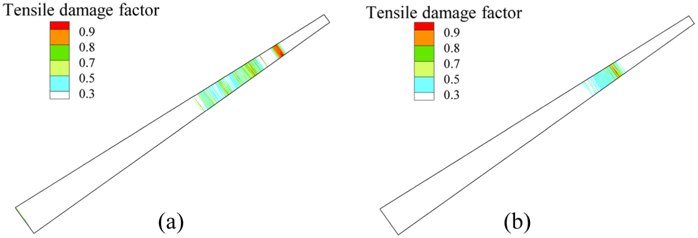
The tensile damage distribution of the concrete face slab at the end of earthquake: (a) USMI and (b) NUSMI.

The tensile damage distribution of the concrete face slab from 0.6 to 0.9 H at the end of earthquake: (a) USMI and (b) NUSMI.
From the dynamic responses study, it is concluded that the USMI method overestimates the dam responses because of ignoring the radiation damping; in this study, the reduction reaches 10%–30% in terms of peak accelerations, compressive stresses, and crest displacements.
Conclusion
The main purpose of this study is to evaluate the effects of the seismic motion input methods on the dynamic responses of CFRDs based on the generalized plastic model. The VSBE was proposed and used for the NUSMI. The NUSMI method and the elasto-plastic finite element procedure for both construction and dynamic analysis were developed and verified. A generalized plastic model for rockfill material has been used and the interface element with asymmetrical nodes is applied to describe the behavior of the interface between concrete face slab and cushion layer. The seismic responses of the CFRD calculated by different seismic motion input methods are compared and investigated. Compared with USMI method, the results show that the acceleration peak value of dam body by NUSMI method decreased about 10%–25%; the horizontal and vertical permanent deformation is about 20% lower and the compressive stress of face slab decreased about 25% at three-fourths of the dam height. It means that the use of NUSMI method leads to about 10%–30% reduction in dynamic response of the CFRD. It indicates that the traditional USMI method would overestimate the responses of the dam. From the perspective of seismic safety evaluation, the overestimations would disturb the reasonable assessment of the aseismic capacity of the dam. Moreover, the slope stability analysis results might be conservative and unreasonable due to overestimating the accelerations during the earthquake.
The 3D dynamic response of CFRDs, particularly which of the Zipingpu Dam during the 2008 Wenchuan earthquake, will be subsequently investigated by extending this numerical procedure, and the propagation effect of the seismic waves on the slab damage and dam deformation mechanism will be discussed. Also, the NUSMI method could be used to study the dynamic responses of the dam constructed on the deep overburden layers considering the nonlinear properties of overburden materials.
Footnotes
Handling Editor: Lalit Borana
Declaration of conflicting interests
The author(s) declared no potential conflicts of interest with respect to the research, authorship, and/or publication of this article.
Funding
The author(s) disclosed receipt of the following financial support for the research, authorship, and/or publication of this article: This work was supported by the National Key R&D Program of China (2017YFC0404904) and the National Natural Science Foundation of China (grant nos 51508071, 51679029, and 51779034). The work is also supported by the Fundamental Research Funds for the Central Universities DUT17LK56.