
Abstract
A concrete plastic-damage model, the extended Drucker–Prager model for rockfill, and acoustic elements for water were introduced and applied to the impact fracture analysis of a concrete-faced rockfill dam–water three-dimensional system. The plastic-damage dynamic analysis process was used in combination with the concrete compressive and tensile damage model. The 223-m high Shuibuya concrete-faced rockfill dam was analyzed using an explicit integration. Numerical simulations of the damage threshold, rockfill modeling, and interface processing were conducted to research the effect of the anti-explosion performance that occurs when a concrete slab is subjected to an underwater shock wave. The simulation results indicate that the main regions of weakness in the slabs during an underwater shock wave are determined by the tensile damage. The slab’s anti-knock weak areas appear in the right dam abutment and the top of the left dam. The anti-knock performance in the upper slab is inferior to that of the lower slab. Specific local optimization steps should be applied at these locations to improve the slabs’ anti-knock capabilities, which are important for designing concrete-faced rockfill dams.
Introduction
Concrete-faced rockfill dams (CFRDs) are an effective and commonly used type of dam. According to incomplete statistics, by the end of 2012, 445 CFRDs had been built that were taller than 30 m, of which 17 are higher than 150 m. According to preliminary statistics, 22 construction projects to build 150- to 250-m-tall dams are currently being planned or are underway. 1 For example, the Shuibuya dam (completed in 2011) is 233 m tall. 2 Concrete slabs play the most important role in CFRDs because they are the main anti-seepage structure. Ensuring that these concrete slabs function safely and reliably is one of the primary concerns in dam engineering research.
At present, extensive research has been performed to analyze the responses of concrete slabs in CFRDs during strong earthquakes. Linear elastic models were widely used for concrete slab research in the past, and this approach has been adopted in the performance of CFRD construction, impoundment, and earthquake response analyses.3–5 Results of the aforementioned research indicate that the concrete’s tensile strength was exceeded; the calculated slab stress is too large, often exceeding the concrete strength, although the calculations do not reflect the release and redistribution of stress after material damage. Nevertheless, slab extrusion and dislocation damage occurred in the Zipingpu CFRD in 2008.6,7 To overcome the shortcomings of linear elastic models, Xu et al. 8 adopted the concrete plastic-damage model9,10 to study the damage development process for concrete slabs under earthquake loading. Using the plastic-damage model, the damaged part of the slab which appears to be softened and the stress is released. The calculation result is more reasonable than the linear elastic model, and the weakness distribution and damage area of slabs can be determined clearly by the damage variable. However, the plastic-damage model does not consider crack cracking and expansion. Using elastic-brittle micromechanical damage models, Xu et al. 11 studied dynamic damage CFRD concrete slabs based on material parameter randomness. The elastic-brittle damage model facilitates the consideration of crack cracking and expansion. Lu et al. 12 used the elastic-brittle damage model to simulate the concrete dam impact failure model test. The results show that the damage degree of numerical simulation is greater than the damage degree of the model test. The difference in loading rates causes the mechanical properties of concrete to exhibit different behaviors, the so-called rate dependence. This is due to the fact that the failure of the concrete material exhibits a diffuse crack distribution in the form of a high strain rate. Therefore, the dynamic strength of concrete increases with the increase in the loading rate. At present, there is a distinct paucity of research on this topic, and the conclusions of the studies that do exist are not in agreement; each of the available models has advantages and disadvantages, and researchers need to rationally select and motivate their choice of an analytical model on the basis of the purpose of the research.
Although the dynamic responses of CFRDs subject to underwater shock waves have also been investigated through dynamic analysis, the response is not the same as the dam dynamic response according to seismic load analysis. First, the impact of underwater explosions is very short, usually milliseconds, and the time of seismic loading is far longer. Second, the underwater shock wave directly affects the upstream surface of the dam, while the seismic wave mainly affects the foundation of the river valley, and the cause of the motion of the dam is hydrodynamic pressure.
Many academics have analyzed the dynamic responses of composite structures and concrete under blast loading in air. Numerical simulation of dynamic response of reinforced concrete slabs subjected to air blast loading was carried out by Tai et al. 13 De Borbón and Ambrosini 14 numerically investigated the dynamic response of carbon nanotube composite sandwich plates subjected to explosion loading. Hosinieh et al. 15 studied the performance of ultra-high mechanical behavior fiber concrete columns subjected to explosion loading. Thiagarajan et al. 16 carried out stress testing of double-reinforced concrete slabs under explosion loading and analyzed the results by finite element (FE) analysis. Chen et al. 17 simulated the mechanical behavior of pre-stressed reinforced concrete beams under blast loading using a numerical method. Liu et al. 18 studied the mechanical characteristics of columns and curved beams on a highway bridge under simplified explosive loading. Although the results of the studies above have provided useful data, the responses of structures to explosions in air and underwater are different. However, the material, structure, and analysis methods can provide a reference for studying blast-resistant measures. The damage to underwater parts caused by an underwater explosion is much larger than that in air. Contemporary research mainly focuses on simple structures, but some scholars have begun to pay attention to the numerical simulation of dynamic characteristics and response of concrete dam structures subjected to the impact of an underwater explosion. Lu et al. 19 carried out model tests under different impact loads, and the results showed that the dam head of a 150-m-high dam had already broken when the shock wave pressure escalated to nearly 4 MPa. Yu 20 used the nonlinear explicit dynamic analysis program LS-DYNA as a platform to establish a two-dimensional full-coupling model of underwater explosions and used an arbitrary Lagrange–Euler (ALE) algorithm to study the dynamic response of the dam to an underwater contact explosion. Linsbauer21,22 studied the dynamic response, stability, and failure mechanism of a concrete gravity dam (upstream surface with crack) under the shock load of a reservoir bottom by establishing a coupled finite element model (FEM) of a reservoir. Wang and colleagues23,24 considered the high strain rate effect of concrete under blast loading. Using the LS-DYNA platform, the full performance numerical simulation of the dynamic response of a gravity dam under different explosion modes was carried out, and anti-explosion measures of reinforcement were carried out. The research was performed, and the effects of underwater and airborne shock waves on the dynamic response and damage degree of the dam were also compared. The research shows that the dynamic response and damage degree of the concrete gravity dam under the underwater explosion impact load are larger than those under the same explosive charge. Chen et al. 25 used the finite element numerical method of fluid–solid coupling to study the development process of gravity dam damage under contact explosion.
Few studies have investigated the dynamic response of CFRDs subjected to underwater explosion shock loads. A 10-kg-TNT-charge underwater explosion in front of a conventional 100-m-tall CFRD was analyzed by Zhang et al. 26 using ABAQUS/Explicit FE software. The analysis indicated that neither the deformation modulus of the rockfill, nor the friction factor of the vertical and peripheral joints, nor the friction factor of the contact between the rockfill and the concrete slab exerted an essential influence on the prediction of concrete slab structural failure. They concluded that the slab remains undamaged when the explosive center is 200 m from the dam site. When the charge weight is light and the explosion is nearby, local damage is done to the dam. However, concrete slabs subject to the breaking of an underwater shock wave experience high-pressure water seeping into the slab, which cushions the layer interface before the cushion layer is washed out. More water seepage in the dam places the dam at risk for total structural failure. A dam in Mexico, with energy dissipation, showed an area of 12 × 12 × 3 m3 when stilling after the crash. A 720-t slab was moved by water flow, and the stilling pool damage range was approximately 46%.
The performance of contemporary weapons has improved, and terrorist activities and local conflicts occur frequently. The “Dam Safety and Security Act,” 27 signed by the American president in December 2002, stipulates the importance of the protection of dams against sabotage. With international economic and political situations changing dramatically, it is important to develop reliable protection systems for CFRDs to ensure the safety of dams and to prevent terrorism or war from affecting the sustainable development of water and energy conservancy. In the absence of such measures, all CFRDs could be in danger. Currently, China faces technical challenges in the development of dams with CFRD heights from 200 to 300 m. This problem should receive more attention in the process of developing CFRDs.
To lower project costs and identify the weak regions of the slabs, local optimization by special means is employed. This study selected a representative sample, the Shuibuya CFRD, with a height of 223 m, as the analysis object. ABAQUS/Explicit FEM analysis was conducted to analyze the damage area of the slabs and the effects of strong shock waves produced by underwater explosions on foundations. The purpose of this study is to determine the anti-knock weak regions of the slabs to provide a reference for anti-knock design. The concrete model adopts the plastic-damage model in which the slab of the damaged part appears to be softened, the stress is released, and the calculation result is more realistic than that of the linear elastic model. The damage distribution and the weak links of the slabs can be clearly understood through the damage variable. The combination of the Drucker–Prager and plastic-damage models offers two advantages: (1) matching of the elastoplastic model of rock-filling material with a concrete model, and (2) calculation accuracy, calculation efficiency, and stability of the numerical calculation program for concrete and rock filler with different models. The same approach can be used to simulate other dam structures subjected to underwater shock waves, and the work is currently under development.
Engineering background
Shuibuya CFRD has a height of 233 m with a width of 12 m on the top and a dam axis length of 660 m; both the upstream and downstream slopes are 1:1.4 each. The materials of the Shuibuya CFRD are partitioned from the upstream to downstream as follows: bedding zone (IIA), transition zone (IIB), main rockfill zone (IIC), secondary rockfill zone (IID), and downstream rockfill zone (IIE). The project began construction in February 2003, reaching a construction height of 405 m in October 2006. The first period of panel construction was from January 2005 to March 2005, the second was from January 2006 to April 2006, and the third was from January 2007 to March 2007. The partitioning of the dam materials and the construction materials is shown in Figure 1. The solid lines represent the material partitioning, and the dotted lines represent the construction partitioning.

The Shuibuya CFRD: (a) sketches of the material zones and construction layers of the Shuibuya CFRD and (b) photo of the Shuibuya CFRD taken from downstream toward the dam wall.
Rockfill body is the CFRD of the supporting structure, functioning to maintain the stability of the dam. The concrete slabs in the upstream face of the rockfill body are the main anti-seepage structure. During the design period, the construction and operation processes of the CFRD should consider four key factors. First, high-level CFRD aseismic design must be the focus of the project. Second, because of the rheology of the rockfill dam, the stress distribution of the dam body is not uniform; this will deteriorate the deformation and stress of the concrete slabs, and the cracks in the face slab, endangering the safety of the dam. The third factor, the corrosion resistance of concrete, is another important index to measure the durability of the CFRD. The fourth factor, the impact of earthquake, creep, and corrosion on the CFRD, poses a potentially fatal risk if anti-knock security is too low. This article considers cases relating to the fourth factor. In theory, the structures under consideration can be thought of as equivalent to a plate on an elastic base, and this approach is taken in this study.
Material model and parameters
Slab and toe board
The plastic-damage model adopted in this article was used to simulate concrete material nonlinearity under the impact of a strong shock wave. The model is based on the isotropic scalar damage hypothesis and is suitable for application in concrete under arbitrary loads. It considers the elastic stiffness degradation caused by plastic strain and has a strong convergence.
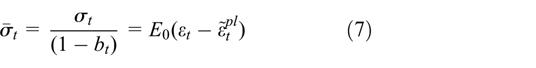
The stress–strain relations are given as follows

Here, b is a variable indicating corruption level and ranging from 0 to 1, where 0 is undamaged, and 1 is complete destruction. The parameters

The Cauchy stress degradation of the effective stress by a scalar variable (d) is given by

For any transverse section of a given material, (1 − b) represents the effective stress region that accounts for a proportion of the total (the total cross-sectional area to cut off the damaged area). In the non-damaged zone (b = 0), effective stress is equivalent to Cauchy stress. While damage does occur, the force is effectively in the non-damaged zone. Thus, the effective stress is more typical of the actual situation than the Cauchy stress. Therefore, the plastic-related formula can be easily established with the effective stress. The yield conditions of the model consider the evolution of the tension and compression strength. According to the effective stresses, the yield condition has the following form
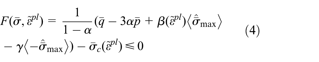
where

where

and
Under the condition of biaxial compression,

where

where

where
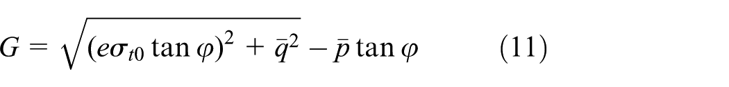
where e is the potential eccentricity of the flow (i.e. the rate of flow of potential, a small positive definition to hyperbolic asymptote, linear eccentricity of the flow potential tends to zero). Then,
The post-failure behavior of concrete generally shows that the stress after failure is a function of the crack strain, under tensile stress,


Illustrations of the cracking strain and inelastic (or crushing) strain: (a) the cracking strain and (b) the inelastic (or crushing) strain.
The tensile damage variable

where
The hardening data cannot be calculated according to the plastic strain,
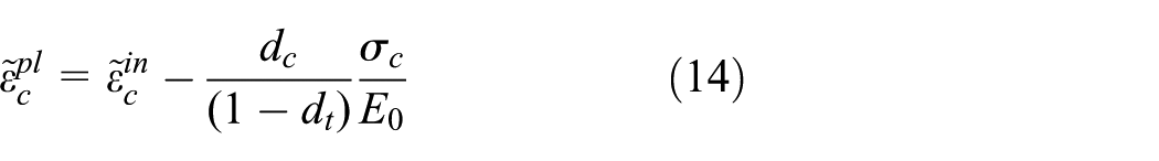
The compressive damage variable
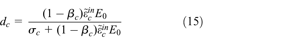
where
The test and simulation curves of concrete in tensile and uniaxial compression are shown in Figure 3, and Table 1 gives the concrete material properties.

Experimental and simulation results of monotonic uniaxial loading for concrete study: (a) tensile simulation and (b) compressive simulation.
Concrete properties.

Rockfill materials
The shock wave caused by an underwater explosion is the first direct effect upstream of the dam, so the concrete slabs are damaged first. Although the available techniques to study the dynamic behavior of dams are based on the generalized models for the rockfills or interface29–33 and on construction and dynamic deformations from numerical simulations, 3 the focus of this study is dynamic concrete slab damage when a slab subjected to strong shock waves. Given the stated focus direction, in this study, the rockfill body is simplified as an elastoplastic material (linear Drucker–Prager model), described using the extended Drucker–Prager model. According to monitoring data in Yang et al., 34 some specific material characteristic data values were used in this research: a bulk density of 22 kN/m3, a modulus of the elasticity of 100 MPa, an angle of friction and dilation of 42°, Poisson’s ratio of 0.35, and a yield stress of 0.2 MPa. In this article, the transition and cushion layer material are the same as in the rockfill processing.
Interface
An approach from Zhang et al. 26 was used to simulate the dynamic contact boundary and analyze the effect of the friction coefficient on the slab damage. The results showed that the effect of changing the coefficient of friction is very small on the slab damage. Under an explosion impact load, there is no unified understanding of the engineering in terms of addressing the contact. To summarize, this article simulates the contact with a non-tensioned concrete plastic-damage model, in which the contact compression model is a concrete compression model. A tensile yield stress of 100 MPa was used in the analysis.
Verification of the reliability of the plastic-damage model for concrete
The preceding sections discussed the fact that the influences of the rockfill material model and interface processing for slab damage are not significant based on the conventional engineering treatment method. As such, we performed the numerical simulation in accordance with that of a previous experiment undertaken by the University of Missouri, Kansas City, and the US Army Engineer Research and Development Center, in order to validate the reliability of the plastic-damage model for concrete. The reinforced concrete slab was constructed using double bi-directional reinforcement, as shown in Figure 4. 16
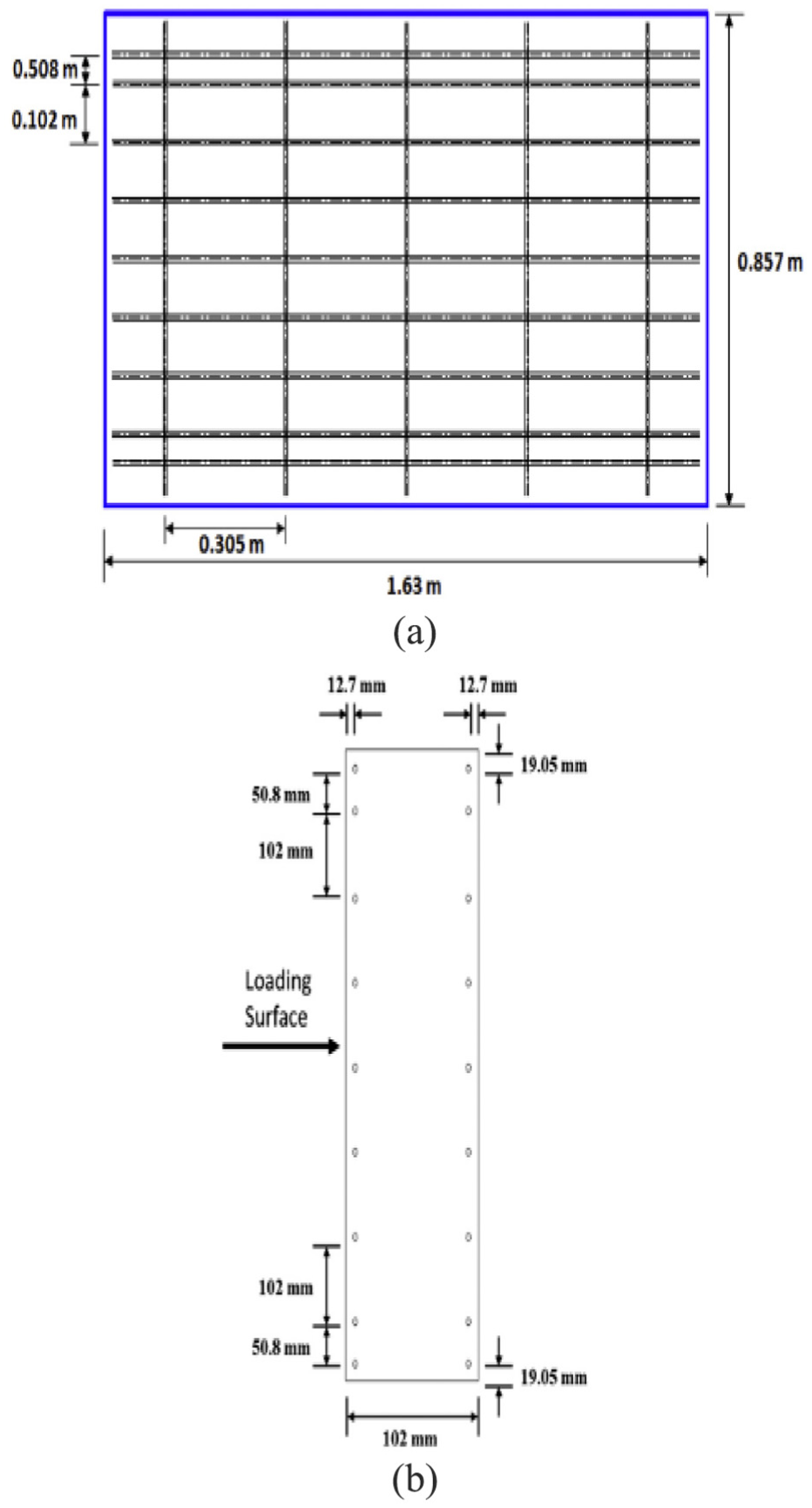
Reinforced concrete slab: (a) plan view and (b) cross section. 16
The elastic–plastic model of reinforcement was used, and the plastic-damage model for concrete was used in the numerical calculations. The reinforcement was simulated by truss elements, the concrete used eight nodes and six solid surface elements, and the mesh size was 25.4 mm. Boundary conditions were exactly as those described in the Hosinieh et al., 15 and the numerical model is shown in Figure 5. The basic input data used for numerical simulation were the pressure versus time curve of the shock wave; Figure 6 shows the shock wave pressure and impulse curve recorded for the slab based on the experimental data in Thiagarajan et al. 16

Finite element model for reinforced concrete slab.

Pressure and impulse histories in Thiagarajan et al. 16
The deflection results of the numerical calculation in this study and the experimental data in the Thiagarajan et al. 16 are shown together in Figure 7. The comparison indicates that the maximum deflection in the numerical simulation is slightly less than the experimental result. The successful calculation of the plastic-damage factor using strain is an indication that the plastic-damage model for concrete was successfully incorporated into this study.
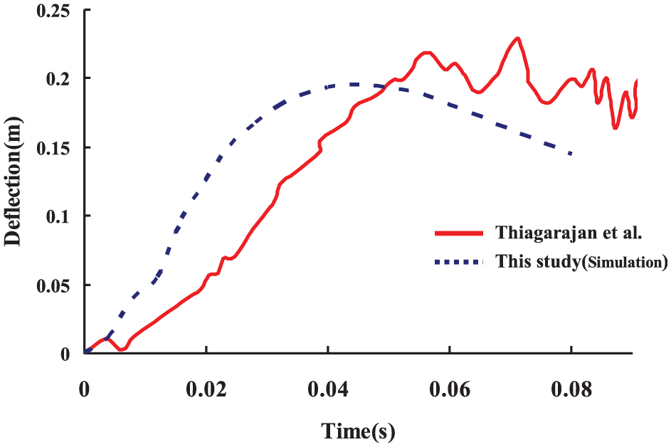
Deflection history.
Dynamic explicit integration algorithms typically employ a dynamics-based time-centered difference format. High-frequency oscillations are difficult to avoid when using the central differential integration rule to perform numerical analysis of strong shock waves caused by explosions, 35 and they are a key factor affecting deflection. However, for the purposes of this study, the authors believe this acknowledged bias is acceptable.
FEM
FE mesh
In accordance with the general characteristics of the Shuibuya dam, a typical homogeneous CFRD model was used for calculation. The study employed a finite element model (FEM) of the dam–water system during the calculation, and the dam foundation was completely restrained. The slab thickness was 0.3 + 0.0035H m, where H represents the dam height. The water level in the Shuibuya dam rises to 215 m. The downstream reservoir water is not considered in the simulation. All parts of the CFRD were simulated by the C3D8R element. AC3D4 elements were used to mesh the fluid (water). C3D8R represents the stress/displacement elements of the eight-node linear brick in the form of reduced integration with an hourglass, and AC3D4 represents the acoustic elements of a 4-node linear tetrahedron in ABAQUS. The density of water is 10 kN/m3, the speed of sound in water is 1500 m/s, and the bulk modulus is 2140 MPa. The sound–solid interaction between the CFRD structural displacements and the fluid mesh acoustic pressures at their common surfaces was implemented in ABAQUS using the *TIE constraint option. Zhang et al. 36 analyzed the sensitivity of the mesh, indicating that the model with a coarse mesh has a failure mode similar to that of one with a fine mesh. This indicates that the sensitivity of the mesh, at least within a certain range, is not relevant to the qualitative analysis of such problems. Owing to the consistent magnitude of the structural model, the magnitude of the mesh size in Zhang et al. 36 was used in this study. The slab elements have the largest mesh size at 0.3 m. In the slab partition, the ratio of the length of each cell is not greater than 1, and the ratio of each unit volume is no more than 3. The time increment scheme in ABAQUS/Explicit is fully automated and does not require user intervention. Figure 8 shows the three-dimensional FE dam model.

FE mesh of the CFRD and water: (a) dam–water system and (b) the slabs.
Determination and simulation of underwater explosion shock load
Of the total energy released by the underwater explosion, about 53% entered the shock wave and 47% entered the bubble pulsation. The pressure amplitude of the shock wave is much larger than the pressure amplitude generated by the bubble. Therefore, the damage to the structure occurred at an early stage and was caused by the impact of the shock wave. This study only considers the effects of shock waves. Jin and Ding 37 show that the transient response of ship structures can be predicted by ABAQUS/Explicit when the structures are under sound wave loads produced by an underwater explosion. The focus of this article is neither on the propagation characteristics of shock waves in water nor on the physical and chemical characteristics of underwater explosives, but on the response characteristics of the dam structures concerned. Therefore, ABAQUS/Explicit is adopted as the platform for numerical analysis.
In the analysis process, when the sound flow behavior is linear, the total sound pressure in the fluid has both a scattered wave component and an incident wave component. This study does not simulate the process of detonation of charges. The pressure of the corresponding head is directly calculated by the Cole formula, and the acoustic–solid coupling method is used instead of the fluid–solid coupling method to simulate the pressure of the dam surface. The research results of Jin and Ding 37 illustrate the rationality of this method for simulating the structural response of underwater explosion shock loads. The characteristic parameters of the incident wave are determined by the experimental data of Kwon and Fox, 38 in which the peak pressure is 15.72 MPa and the duration is 0.002 s, as shown in Figure 9. The selected experimental results show that there is no obvious fluid cavitation phenomenon, and no bubble pulse occurs. The scattering wave is the sound field produced by the interaction between the incident wave and the concrete face rockfill dam structure in the special instructions; the fluid–structure coupling phenomenon caused by an underwater shock wave and the hydrodynamic pressure generated by an earthquake are different. 39

Time history curves of incident wave loading.
On the premise of not increasing the number of water grids, a more reliable and widely used Cole formula is used to calculate the pressure history at the reference point. The Cole empirical formula yields

where
The location of the focal point corresponds to the actual location of the explosive. The position of the standoff point corresponds to the position of the incident wave when analysis begins and provides a view of the history of the incident wave pressure. To improve the solution efficiency, the standoff was placed at the junction of the fluid structure and nearest to the source point. The standoff can be far away from the structure and near the focus, but this only causes a delay in the transient response. In no case can the standoff point be placed within the field of analysis or behind it. For a spherical shock wave, the relative positions of the standoff point and the source point determine that the pressure of the wave will attenuate as the distance between the sources decreases, that is

where
For the undamped plane wave, the propagation direction of the incident wave is determined by the distance and the relative position of the source point. The plane wave is the more extreme situation; the damage effect on the slab under the same incident wave would be more significant. Thus, the main purpose of this study is to select the plane wave calculation to compare its effect on the main factors more clearly. In this research, the different load calculations are divided into three types, as shown in Figure 10.

Load types for the shock wave: (a) planar wave, (b) spherical shock wave and the standoff point in the upper part of the slabs, and (c) spherical shock wave and the standoff point in the lower part of the slabs.
Results and discussion
This article considers concrete compression and tensile damage. In the shock load simulation in Figure 9, regardless of the calculation conditions, the slabs did not appear to show compression damage. Thus, only tensile damage of the slab is analyzed in the following discussion. In addition, the performance of the floor subjected to an underwater shock wave is studied, and the construction results and water storage simulation are not introduced in this article.
Influence of the damage threshold
In this section, the load is applied to the plane wave, as shown in Figure 10(a). The damage variable exceeded the damage threshold in certain elements, which indicates that macro-fractures would occur in the slab structure. Different damage thresholds were set under the same calculation conditions, to observe the slab macro fracture results. The damage thresholds used were 0.75, 0.80, 0.86, and 0.90. The simulation results are shown in Figure 11.

Structural failure range of the concrete face with different damage thresholds: (a)
The results from different damage thresholds in Figure 11(a)–(d) show that the damage areas of the slabs change significantly. The primary purpose of this study is to determine the damage areas and positions of weakness in the slabs during an underwater explosion shock wave using the damage variable. Determining accurately the corresponding relationship between the crack state and the damage variable is not the focus of this article. Zhang et al. 26 suggested that the tensile damage exceeded 0.8 in certain elements when macro-fractures would occur. Thus, in the subsequent analysis, the damage threshold is set to 0.8.
Influence of the rockfill model
A summary of the Kong et al.,
29
of CFRD performance parameters and dam deformation monitoring data, shows that the rockfill deformation modulus has a valley shape, with the nature of the rock and compaction changing in a certain range and with a basic value of less than 200 MPa. In the scope of practical engineering, the elastic modulus values of rockfill have negligible impact on slab damage. This was attributed to the substantial difference in rockfill and concrete slab stiffness caused by the considerable differences in wave impedance

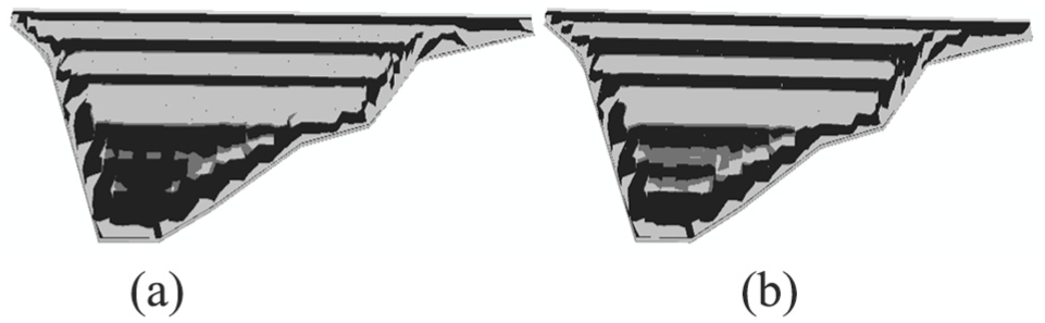
Structural failure range of the concrete face with different models of the rockfill
The results from different rockfill models in Figure 12(a) and (b) show that the damage area of the slabs is basically the same. The rockfill material model prediction of the final slab damage can be considered to show the considerable influence of the underwater explosion shock loading.
The influence of interface processing
Interface processing was employed to address the dynamic frictional contact boundary. The results showed that varying the friction coefficient does not significantly change the slab damage effects with the dynamic frictional contact boundary. General engineering of the contact region of the slab is not permitted due to the tension. In this section, interface processing was adopted in the concrete plastic-damage model, but not in the tensile concrete plastic-damage model (a tensile yield stress of 100 MPa was used in the analysis). Figure 13 shows that the tensile damage variable
Structural failure range of the concrete face with different models of the interface
The results from different interface processing in Figure 13(a) and (b) show that the damage area of the slabs changes very little. This is mainly due to the initial slab damage. Interface processing predicted that the final slab damage was significantly influenced by the underwater explosion shock loading. Therefore, to accurately simulate the interface, it is processed according to the general engineering experience.
Anti-knock performance of the slabs
A spherical shock wave is defined by the relative positions of the source point and standoff point. In the upper and lower parts, two slab locations were selected as the standoff points, respectively, and the nearest distance of the explosion source to the reference point was taken as 50 m, as shown in Figure 10(b) and (c).
For the completely brittle failure criterion, when the tensile stress reaches the tensile yield strength σt0, macro-fractures will occur in the concrete. However, for the quasi-brittle failure criterion, the tensile damage variable exceeded 0.8, which suggested that macro-fractures would occur in the slabs. Figures 14 and 15(b) and (c) show two kinds of working conditions of the slab damage range, respectively.

The failure distribution of the slab for different failure criteria when the standoff point is in the upper slab: (a)

The failure distribution of the slab for different failure criteria when the standoff point is in the lower slab: (a)
Figures 14 and 15 show that the right dam abutment and the left dam – at the top of the slabs – are fractured completely according to the quasi-brittle failure criterion, indicating that these two areas are the slabs’ anti-knock weak areas. For the standoff point in the lower slab, only a small range is damaged completely according to the brittle failure criterion (shown in Figure 15(a)). According to the quasi-brittle damage criterion (shown in Figure 15(b)), no damage occurs around the standoff point. For the standoff point in the upper slab, the degree of slab damage is more serious than the standoff point in the lower part, mainly reflecting that the reference points in the surrounding area experienced more serious damage (Figure 14(a) vs Figure 15(a), and Figure 14(b) vs Figure 15(b)). This indicates that the anti-knock performance is higher in the lower slabs than in the upper slabs.
The results from different failure criteria in Figures 14 and 15 show that using the completely brittle failure criterion results in a more serious damage than the quasi-brittle failure criterion. Because concrete material is a type of quasi-brittle material, using the quasi-brittle failure criterion more closely resembles the actual situation.
Conclusion
A concrete plastic-damage model, the extended Drucker–Prager model for rockfill, and acoustic elements for water were introduced in the article and applied, respectively, to the impact fracture analysis of a CFRD–water three-dimensional system. The plastic-damage dynamic analysis procedure was used to program the concrete compressive and tensile damage model. The 223-m high Shuibuya CFRD was analyzed using an explicit integration. The main work and conclusions are as follows:
The influences of the rockfill model and interface processing on slab damage are not significant. The nature of the concrete slab is the major structural factor affecting the anti-knock performance according to qualitative inference. In practical applications, simplifications can be made based on experience.
In this article, compressive damage and tensile damage models are both considered, but the compressive damage does not appear in all slabs. The main tensile damage areas and weakness in the slabs during the underwater shock wave were clarified by the positions’ damage variable. The slab anti-knock weak areas appear in the right dam abutment and the top of the left dam. In the upper slab, the anti-knock performance is inferior compared with that in the lower slab. Particular local optimization steps should be applied at these areas to improve the slabs’ anti-knock capabilities.
Because concrete material is a type of quasi-brittle material, using the quasi-brittle failure criterion rather than the completely brittle failure criterion is more appropriate. However, understanding the accurately corresponding relationship between the crack state and the damage variable requires further research.
In practical engineering applications, based on the Cole empirical formula for considering various explosion conditions to obtain a series of achievements, a comprehensive reference can be provided for the blast-resistant design of a dam. In addition, this method can be used for the assessment of dam, other anti-seepage structure damages, and underground concrete anti-seepage walls, plinths, and junction plates.
Footnotes
Handling Editor: Guian Qian
Declaration of conflicting interests
The author(s) declared no potential conflicts of interest with respect to the research, authorship, and/or publication of this article.
Funding
The author(s) disclosed receipt of the following financial support for the research, authorship, and/or publication of this article: This study was supported by the Natural Science Foundation of China (under grant nos 51741904, 51708245, and 51508071) and the State Key Laboratory of Coastal and Offshore Engineering of China (under grant no. LP1714).