
Abstract
Equivalent linear dynamic analysis is the primary method of analysis for concrete-faced rockfill dams during earthquake. However, this method cannot be directly used to estimate permanent deformation during earthquake, which is important to evaluate the dynamic safety of concrete-faced rockfill dams. To bridge this gap, an elasto-plastic dynamic response procedure based on finite element method is presented to estimate the construction, impoundment, and dynamic characteristics of concrete-faced rockfill dams. This procedure involves a generalized plasticity model for rockfill materials and an ideal elasto-plastic model for interface between concrete face slab and rockfill material. The construction, impounding process, and seismic behavior of a 150-m-tall concrete-faced rockfill dam were simulated using seismic motion based on Chinese code for seismic design of hydraulic structures of hydropower project with the peak ground acceleration of 0.3g as an excitation to validate the procedure. On the basis of the numerical simulation results of the step-by-step construction, reservoir impoundment and seismic response of a concrete-faced rockfill dam, dam settlement, joint deformation, stress, and deformation of slab were analyzed. The results indicate that the dam settlement and deformation of joint can be directly obtained by the procedure during earthquake. The construction, impoundment, and seismic analysis could be considered in one procedure.
Keywords
Introduction
The seismic safety of concrete-faced rockfill dams (CFRDs) is becoming increasingly important, as these structures are being constructed worldwide at unprecedented rates. The deformation of CFRDs is significant for evaluating the safety of dam both during construction and during an earthquake. Excessive deformation would lead to the separation of the face slab from the cushion layer and cause damage to vertical joints and peripheral joints of the slabs. Such damage would reduce the safety factor of the structure due to seepage failure. At present, the numerical simulation of CFRDs mainly consists of (1) the step-by-step construction, (2) the dynamic response, and (3) seismic residual deformation analysis. When analyzing these complicated phenomena, several procedures are sequentially or repeatedly used because each procedure typically has only one function. Several computer procedures must be employed to analyze a variety of phenomena. Furthermore, different models are used for different types of simulations. For example, the Duncan-Chang model 1 for rockfill material has been widely applied for simulating construction, and the equivalent linear model 2 is often applied for dynamic response analysis. Previous studies of the construction, impoundment, and seismic behavior of CFRDs have mainly used the Duncan-Chang model and an equivalent linear method. Such investigations include studies by Uddin and Gazetas, 3 Mejia and Seed, 4 Gazetas and Dakoulas, 5 Samiento et al., 6 and Dakoulas. 7 For example, Uddin 8 developed a two-dimensional (2D) procedure for CFRD dynamic analysis with an equivalent linear model for rockfill, and Dakoulas 7 used ABAQUS to analyze the dynamic responses of a three-dimensional (3D) CFRD in a narrow canyon. However, dynamic analysis based on the equivalent linear model cannot obtain the seismic residual deformation of a CFRD. In order to solve this problem, two approximate methods have been mainly employed to evaluate residual deformation of dams after earthquake. One is the limit equilibrium method based on rigid-plastic blocks (e.g. the Newmark 9 sliding block method) which is on the concept of yield acceleration; the other is the global deformation analysis method on the basis of the concept of strain potential presented by Serff et al. 10 In the above two methods, the process of dynamic calculation during earthquake and residual deformation computation after earthquake are separated artificially and not uniform.
With the accumulation of dam construction experience and the improvement of dam design, a number of earth and rockfill dams higher than 150 m have been built and higher than 250 m in plan, such as Zipingpu, 11 Nuozhadu, 12 Houziyan, 13 Gushui, 14 and Shuangjiangkou. 15 These dams are located in the high seismic intensity area in China. With increasingly dam height and the strictly aseismatic design standard, conventional finite element (FE) procedures and models for rockfill cannot satisfy the engineering needs of high CFRDs. In traditional analysis of earth and rockfill dams, middle increment method is adopted in static calculation and the equivalent linear method in dynamic calculation. Neither method is rigorous enough to consider the non-linearity of materials. Therefore, the authors have designed a 3D elasto-plastic dynamic FE procedure, GEODYNA (Geotechnical Dynamic Nonlinear Analysis), which is a multi-purpose computer code and the iterative method is adopted for the construction, impoundment, and dynamic analysis of CFRDs based on the effective stress concepts. Rockfill materials of the generalized plasticity model and the interface of the ideal elasto-plastic model between face slab and rockfill material are involved in the procedure.
Advanced technologies for procedure design
Object-oriented method and parallel computing technology were used for designing the GEODYNA procedure.
Object-oriented
Object-oriented is compared to process-oriented. It replaces “structured” as the high-technology version of “good” visualization in many cases. 16 It puts both states (data) and behaviors (processes, manipulation of data) together as an interdependent and non-separable whole. In traditional analysis methodologies, the two aspects are considered separately. The object-oriented method abstracts its generality into the same type object and forms the class. Most of the data in a class can only be processed using this class method. The class communicates with the outside data through a simple external interface, and the object communicates with the other object through messages. In this way, the relationship between program modules is simpler, and the independence of program module and the security of data are well guaranteed. In addition, inheritance and polymorphism can greatly improve the reusability of the program, and the development and maintenance of software will be more convenient.
Parallel computing
Most procedures developed for geotechnical engineering by researchers have adopted the conventional serial computation method, in which only one central processing unit (CPU) is used when analyzing a model. With the improvement of computer technology, the parallel computation method has been applied widely in numerical analysis. Many CPUs are used to solve a problem at the same time in parallel computing. Large problems are divided into smaller ones. And then they can be solved simultaneously. This technology is used in the procedure of GEODYNA to improve the computation speed, especially for the large-scale elasto-plastic problem.
For the element equivalent stiffness matrix (including the stiffness matrix, damping matrix, and mass matrix), the generation of the equivalent load vectors, stress integral calculation of constitutive model, and the solution of the equations, the OpenMP model is adopted to realize the parallelization in the procedure of GEODYNA.
The functions of the procedure
For over 30 years, with the rapid development of the computational soil mechanics, the FE method, and computer technology, the researchers have developed computation procedures for analysis of geotechnical engineering, such as FEADAM, 17 QUAD4, 18 SWANDYNE, 19 CRISP, 20 SHAKE, 21 and FLUSH. 22 These procedures generally adopt process-oriented development method with single function, non-uniform interface, poor portability and maintainability, and low development efficiency. And commercial software (e.g. ABAQUS) have strong universality but poor specialty. The complexity of the secondary development of geotechnical problem requires more development degrees of freedom, but it provided less interfaces. The operation process of codes cannot be tracked, so debugging is difficult. Therefore, the advanced development technologies have been applied including Windows development platform, Visual c++ language and MFC development environment, the object-oriented design method, multi-core parallel computing, the graphical interface for users, and so on.
The basic functions and computing efficiency
The procedure is consistent with the command stream input method, the element activation method, the strain potential function method, and the time integral method. The processes of static and dynamic analysis including filling, foundation excavation, consolidation deformation, wetting deformation, creep analysis, seismic liquefaction, dynamic response, and seismic deformation are integrated and unified in GEODYNA. The whole process of complex stress during construction, operation, and earthquake can be simulated by the procedure. In addition, it has convenient and complete post-processing function, which is convenient to display results and output graphics.
By adopting advanced technologies such as non-zero storage of sparse matrix, multi-core parallel of OpenMP, dynamic memory allocation and collection, and iterative solution of equations, the computation scale and speed of procedure are significantly improved. For a 3D FE dynamic calculation (over 2 million degree of freedoms, and 1500 calculation steps), it only takes 3 h in a 24-core CPU computer.
The types of FEs, loads, and constitutive models
Abundant libraries of FE types, load types, and geotechnical material constitutive models are integrated in the procedure of GEODYNA.
The library of FE types includes structural FE classes and continuous and discontinuous media block FE classes. The structural FE classes include mass element, beam element, link element, and spring element. The continuous media block FE classes include solid media element, fluid media element, and coupling element. The class discontinuous media block FE classes include normal interface element and coupling interface element.
The library of load types includes element constant load (e.g. for simulating gravity), element load changing over time (e.g. for simulating inertia force), node constant load, node load changing over time, surface force load (e.g. for simulating hydrostatic pressure), strain potential load (e.g. to calculate equivalent nodal force used in the wet and creep analysis), the seepage load to simulate the seepage force, and earthquake acceleration load used to simulate the ground motion input.
The library of geotechnical material constitutive models includes stress–strain model classes, seepage model classes, and pore pressure model classes. The stress–strain model classes include the linear elastic model, the nonlinear elastic model (e.g. the Duncan Chang E-B, Duncan Chang E-ν, the hyperbolic contact surface model), the equivalent linear model (e.g. Hardin model), and elasto-plastic model (e.g. generalized plastic model, the ideal elasto-plastic model). The seepage model class is mainly isotropic seepage models. Pore pressure model class is mainly seismic pore pressure models.
Application in practical analysis of project
The procedure has been successfully applied in earth and rockfill dams of Chinese water resources and hydropower engineering such as Zipingpu (156 m in height), Jilintai (157 m in height), Nuozhadu (261.5 m in height), Shuangjiangkou (314 m in height), Lianghekou (295 m in height), and Houziyan (223.5 m in height). The damage state and limit aseismic capacity of dam in strong earthquake zone can be solved using GEODYNA.
CFRD model
The FE discretization of a 150-m-tall CFRD is plotted in Figure 1. The slope ratios of the dam are as follows. The upstream slope ratio is 1.0/1.4 (vertical/horizontal) and the downstream is 1.0/1.5. The left bank slope ratio is 1.0/1.0 and the right bank is 1.0/1.5. Figure 2 shows the longitudinal section of the dam.
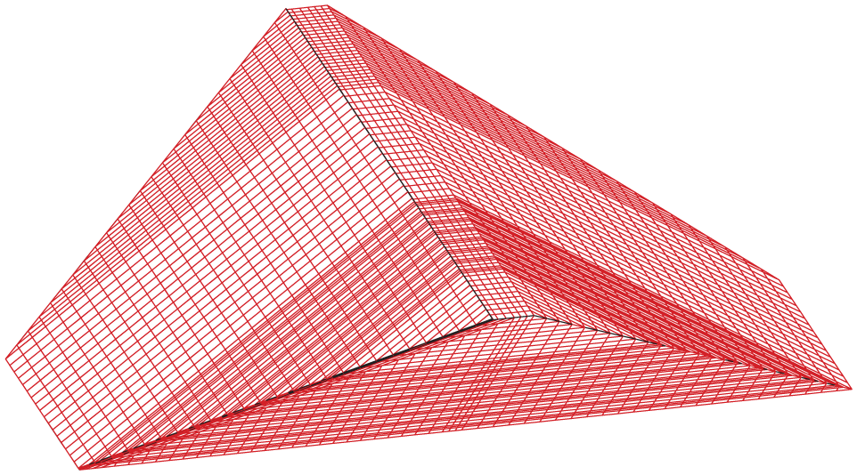
The FE discretization of a 150-m-high CFRD.

Longitudinal section of the dam and rock base.
Three stages are used for pouring of face slabs; the elevations of the slabs are 60 and 110 m at different stages. In the 3D FE mesh, there are 41,797 elements. Spatial eight-node isoparametric elements are used by most of rockfill materials and slabs. In the FE model, the dam was assumed to be located on a rigid rock base. So the bottom and river bank boundaries of the dam are fixed in all directions. The surface forces on the face slabs during impounding were simulated by the water pressure. The adding mass method for hydrodynamic forces of the face slabs were used in the dynamic analysis. 23 It can be calculated by “Specifications for seismic design of hydraulic structures” (DL 5073-2000). 24
Constitutive model for FE
In this procedure, the generalized plastic model 25 modified for the rockfill materials of high rockfill dam was employed and the ideal elasto-plastic interface model 25 for interface between face slab and cushion gravel was used. The concrete face slabs were simulated by the linear elastic model. The vertical joints and peripheral joints of face slabs were simulated by Goodman contact element.26,27
Parameters of materials
Concrete face slabs and rockfill
As a linear elastic model applied to simulate the concrete face slabs, the material properties were assumed as follows: the density ρ is equal to 2.40 g/cm3, elastic modulus E is 25.5 GPa, and Poisson’s ratio ν is 0.167.
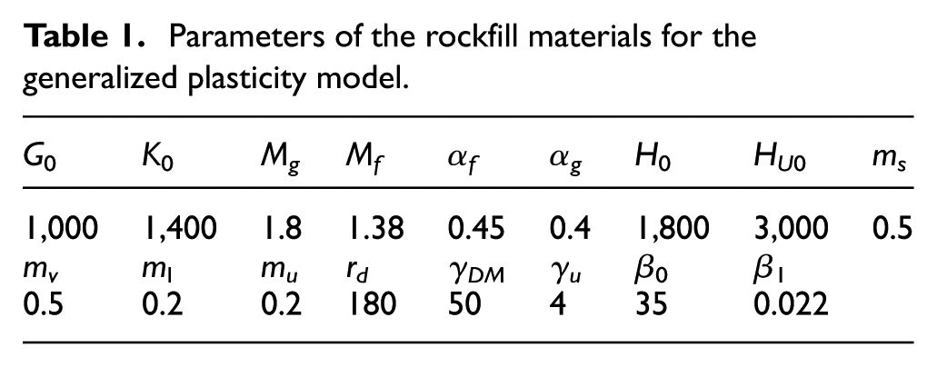
There are 17 parameters in the modified generalized plastic model for rockfill materials. The parameters can be divided into elastic and plastic parts. The elastic part includes initial shear modulus parameters (G0 and ms) and initial volume modulus parameters (K0 and mv). The plastic part includes parameters related to plastic flow direction and plastic loading direction (αg, αf, Mg, and Mf) as well as parameters related to plastic modulus. The detailed material properties are provided in Table 1. 25
Parameters of the rockfill materials for the generalized plasticity model.
Interface
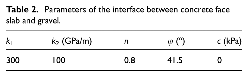
Zhang and Zhang 28 studied the strength and deformational behavior of interface between concrete face slab and cushion gravel. Table 2 shows the parameters of the ideal elasto-plastic model which were determined by the experimental results. 28 Figure 3 shows the comparison of model predictions and experimental results of the stress–strain relationship under cyclic loading. The parameter k2 is compressive stiffness constant in the model. For preventing interface penetration, k2 was assumed to be 10 GPa/m.
Parameters of the interface between concrete face slab and gravel.

Comparison of the model predictions and test results of the stress–strain relationship of the concrete–gravel interface.
Vertical joints and peripheral joints of face slabs
The woods are filled in the vertical joints and peripheral joints of face slabs. It can prevent hard contact between concrete face slabs. According to the elastic modulus of the wood, 27 the compressive stiffness of the joints was 25 GPa/m in this study. 11 The tensile stiffness was 5 MPa/m, and 1 MPa/m was used for the shear stiffness in the constitutive model. The parameters used in static and dynamic analysis are consistent.
FE analysis
Simulation of the staged construction and impoundment
The simulations of the staged construction and impoundment process were performed in 31 and 29 steps, respectively. The water level at full reservoir was 145 m. The thickness of each construction layer was 5 m, and each impoundment step was also 5 m.
Dam settlement
Figure 4 illustrates the simulated settlement of the dam’s middle cross section at the end of construction (step 31). The maximum settlement was 0.7 m. The field record of the Zipingpu Dam in China (a 156-m-tall CFRD) indicated that the maximum settlement of the dam was approximately 0.8 m 25 after Wenchuan earthquake. The distribution of the simulated settlement is similar to the field observations. 25

Distribution of the simulated settlements at the end of construction.
Slab stress
The response of the CFRD during reservoir impounding was calculated by the proposed numerical procedure (GEODYNA). The distributions of stresses (along the slope direction and along the dam axis direction) in the face slabs after impoundment are illustrated in Figure 5(a) and (b), respectively. Along the slope direction, the maximum compressive stress was 3.4 MPa, and the maximum tensile stress was 1.9 MPa which occurred in the bottom of the slabs. Along the dam axis, the maximum compressive stress was 4.0 MPa, and tensile stress was located along the two side banks. The slab stress results are consistent with the trend simulated by Xu et al. 25

Distribution of stress in the slabs after impoundment (compressive stress is positive, unit: MPa): (a) along the slope and (b) along the dam axis.
Joint deformation
In order to determine the direction of joints displacement, Figure 6 shows the direction of positive and negative definitions of the joint deformations. Figures 7 and 8 illustrate the deformation of the peripheral joints and vertical joints after impoundment. After impoundment, the maximum deformation of the peripheral joints along the direction of the plinth, normal to the plinth, and the opening displacement reached 2.49, 1.86, and 0.26 cm, respectively, without the occurrence of embedded deformation. The maximum deformation of the vertical joints along the direction of the slope, normal to the slab, and opening displacement reached 1.68, 0.28, and 0.51 cm, respectively, and a small compressive deformation of 0.02 cm occurred. The field records of the deformation of the peripheral joints of several CFRDs after impoundment are provided in Table 3. The simulated results in this article are similar to those observed in the field.

Positive and negative definitions of the joint deformations: (a) peripheral joints and (b) vertical joints.

Deformation of the peripheral joints at the end of impoundment (unit: cm): (a) along the plinth, (b) normal to the plinth, and (c) opening displacement (opening taken as positive).

Deformation of the vertical joints at the end of impoundment (unit: cm): (a) along the slope, (b) normal to the slab, and (c) opening displacement (opening taken as positive).
Field-measured joint deformations of several CFRDs.
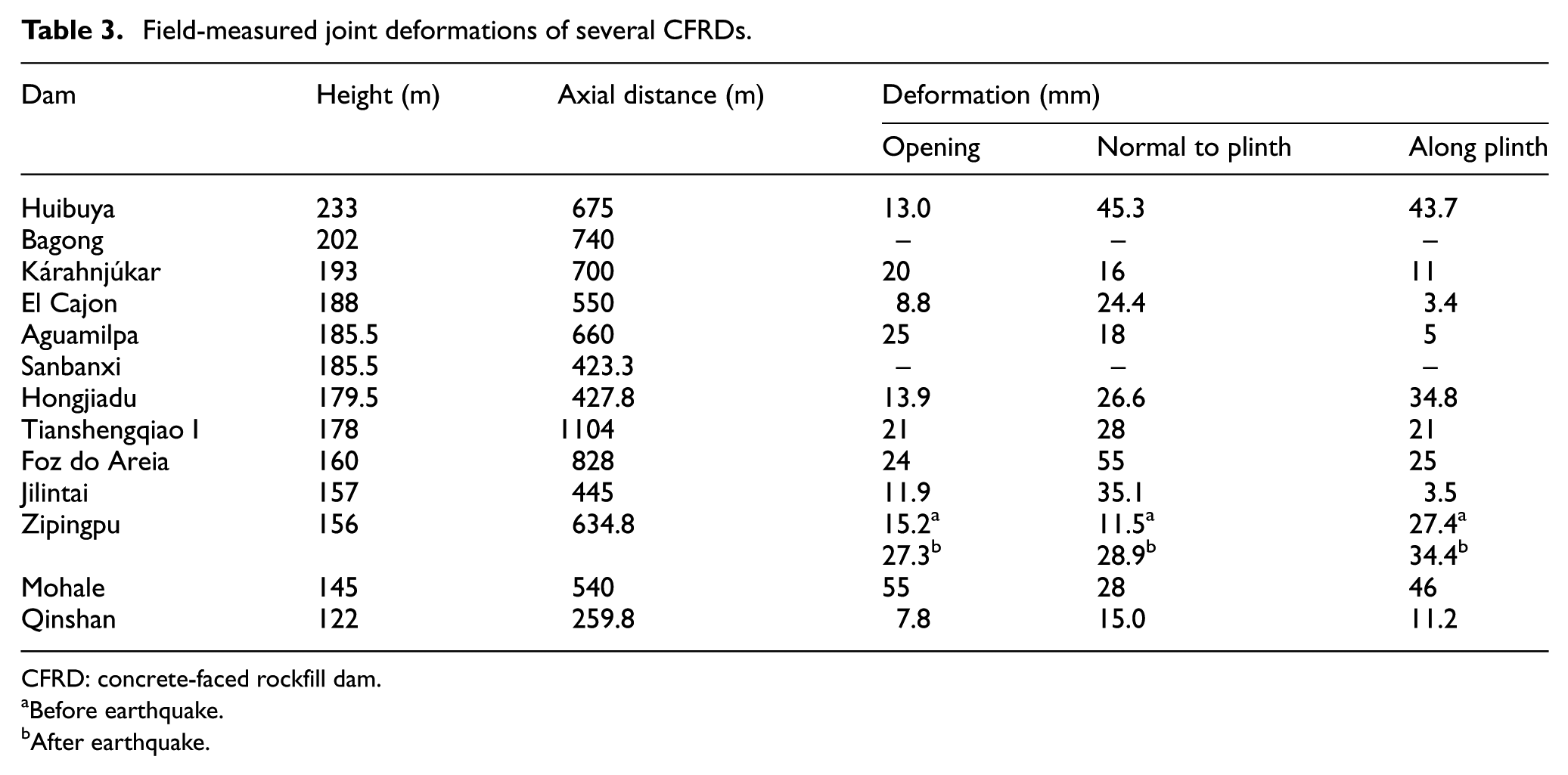
CFRD: concrete-faced rockfill dam.
Before earthquake.
After earthquake.
Dynamic analysis
Damping
The damping matrix is related to the viscosity coefficient of the material, and Rayleigh damping is generally adopted in the FE analysis. For non-uniform materials such as soil, the element damping matrix is first calculated by equation (1) and then assembled

where αe and βe are damping coefficients.
According to Rayleigh damping, damping ratio he can be expressed as

where he can be obtained by the relation curve of damping ratio and shear strain, ω = 2πf is the circular frequency. This method leads the correlation between damping and frequency. However, the damping of soil is independent of the frequency.
Hudson et al. 29 established a new method to determine the value of Rayleigh damping coefficient. In this method, two frequencies ω1 and ω2 were used to determine αe and βe. ω1 is assigned as the base frequency of the structure and ω2 = nω1, where n is an odd number greater than ωe/ω1 and ωe is the main frequency of seismic waves. Therefore, αe and βe can be expressed as


In this study, the damping ratio for the concrete slab and rockfill zone was assumed to be 5% in the dynamic analyses. 30
Input motion
Figure 9 shows the time histories of seismic input in three directions. In the horizontal direction (including upstream-downstream and the dam axial directions), the peak ground acceleration (PGA) was 0.3g. The vertical PGA is 0.2g. The time histories of seismic motion were generated by the code spectrum of the Chinese codes for seismic design of hydraulic structures of hydropower project (DL 5073-2000). 24

Earthquake motion input: (a) upstream-downstream direction, (b) vertical direction, (c) dam axial direction, and (d) acceleration amplification response spectrum.
Dam settlement
The contour of the dam settlement after the earthquake was presented in Figure 10. The maximum settlement reached 0.45 m. The position of maximum settlement was at the top of the dam of central valley. Figure 11 plots the time histories of the upstream-downstream direction deformation and settlement of the dam crest. It can be seen that the horizontal displacement was mainly from upstream direction to downstream, and the settlement increased gradually during shaking. These results indicate that the residual deformation of dam can be directly obtained by the procedure during earthquake with a generalized plasticity model for the rockfill material.31–35

Contour of dam settlement after the earthquake (unit: m).

Mid-crest displacement history of the dam during the earthquake: (a) upstream-downstream displacement and (b) settlement.
Slab stress
Figure 12 illustrates the distribution of the slab stresses (along the slope direction and along the dam axis direction) after earthquake. Along the slope direction, the maximum compressive stress was 8.4 MPa, whereas along the dam axial direction it was 13.0 MPa in the slabs near the crest, which might result in extruding damage in the area. During the Wenchuan earthquake, significant extruding damage occurred at the similar position in the slabs of the Zipingpu Dam (Figure 13).

Contour lines of slab stress after the earthquake (compressive stress is positive, unit: MPa): (a) along the slope and (b) along the dam axial direction.

Extruding damage of the face slab of the Zipingpu Dam at elevations of 790–828 m during Wenchuan earthquake.
Joint deformation
During the earthquake, deformation clearly occurred in the peripheral and vertical joints. Figures 14 and 15 illustrate the deformation of the peripheral and vertical joints after earthquake. The maximum deformation of the peripheral joints along the direction of the plinth, normal to the plinth, and the opening displacement reached 3.21, 2.57, and 1.63 cm, respectively, without the occurrence of embedded deformation. The maximum deformation of vertical joints along the direction of the slope, normal to the slab, and the opening displacement reached 3.80, 0.52, and 3.89 cm, respectively, and a small compressive deformation of 0.12 cm occurred. The numerical results were of the same order of magnitude from the field records of the Zipingpu CFRD after Wenchuan earthquake (Table 3).

Deformation of the peripheral joints after the earthquake (unit: cm): (a) along the plinth, (b) normal to the plinth, and (c) opening displacement (opening taken as positive).
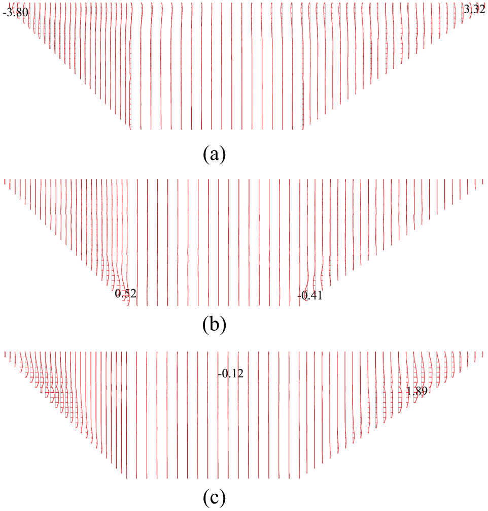
Deformation of the vertical joints after the earthquake (unit: cm): (a) along the slope, (b) normal to the slab, and (c) opening displacement (opening taken as positive).
Conclusion
Based on the object-oriented method and parallel computing technology, we developed a 3D elasto-plastic dynamic response procedure for CFRDs. Rockfill materials of the generalized plasticity model and the interface of the ideal elasto-plastic model between face slab and rockfill material are involved in the procedure. The construction and impounding processes and seismic analysis were combined in the same procedure.
During the earthquake, the procedure could directly obtain seismic residual deformation of the dam without using the residual deformation model for rockfill material to calculate the permanent deformation after earthquake. The deformation of the joints could also be calculated during the construction, impoundment processes, and the earthquake.
Along the dam axial direction, the maximum compressive stress of face slab occurred near the dam crest of central valley after earthquake; this result should be considered in the aseismic design of CFRDs.
Footnotes
Handling Editor: Lalit Borana
Declaration of conflicting interests
The author(s) declared no potential conflicts of interest with respect to the research, authorship, and/or publication of this article.
Funding
The author(s) disclosed receipt of the following financial support for the research, authorship, and/or publication of this article: This work was supported by the National Key R&D Program of China (2017YFC0404900) and the National Natural Science Foundation of China (Grant Nos 51508071, 51679029, and 51779034). This work was also supported by the Fundamental Research Funds for the Central Universities DUT17LK56. This financial support is gratefully acknowledged.