
Abstract
In this article, we introduce an image sensor–based optical vehicular communication system for performing vehicular condition resolution adaptively in the spatial domain and the temporal domain. To validate the proposed system, a dual camera–based approach is presented here, where a vision camera is used to detect multiple vehicles of interest (i.e. spatial condition), a communication link is set up, and then, a high-speed camera adapts its resolution to ensure fast processing and high-rate data communication (i.e. temporal condition). We suggest an adaptive algorithm that supports the detection of and communication multiple vehicles simultaneously in spatial-temporal condition. Moreover, we propose a combination of scale-invariant feature transform and iterative closest point for detection and classification of multiple vehicles. To prove the feasibility of our proposed scheme, we present simulation results.
Keywords
Introduction
In the present technologically developed world, connectivity among devices is expected to increase dramatically. The concept of establishing communication among devices is promising and inter-vehicle communication has been attracting massive attention from academia and industry. Many researchers are attempting to develop the best automotive vehicle (AV) solutions. However, due to the absence of commercially available vehicles equipped with such solutions, with most vehicles using fixed and standardized technologies, the optimal technology remains unclear. In addition, new automotive technologies must be implemented considering the regulations on the use of AV technology to ensure human safety and user trust on the machine. Google’s AV has driven for more than 500,000 miles without crashing. However, the system relies on gathering information about driving conditions from around the world on increasingly complex and sophisticated algorithms to process sensor data and to control the vehicle. Correspondingly, it requires massive computational power to operate in real time. Certain AV systems use combinations of various sensors; however, these sensors can interfere mutually when collecting those data. Other vehicular localization systems use the global positioning system (GPS), radio detection and ranging (RADAR), light detection and ranging (LiDAR), or ultrasonic signals for positioning or ranging.1,2 However, these technologies are fraught with challenges. The use of radio waves in GPS-based positioning systems creates some problems such as radio interference error, reduced security, and multipath propagation. The LiDAR system requires complicated equipment which makes it extremely expensive system. In addition, it does not include any mechanism for communication with surrounding vehicles or infrastructure and can be used only for ranging or building three-dimensional (3D) image points. Given that information about road surroundings will be the most significant factor for next-generation intelligent transportation systems (ITS), its incorporation with existing systems is one of the toughest challenges in developing an ultra-reliable AV system.
However, visible light communication (VLC), as a part of optical wireless communication (OWC), has attracted considerable attention for potential next-generation communication services,3,4 and much of the potential of VLC can be ascribed to its use of light-emitting diodes (LEDs). Over the past few decades, the use of LEDs in lighting infrastructure has increased due to its advantages, such as energy efficiency, low cost, and extended lifespan. In addition to performing the essential functionality of lighting applications, LEDs can be switched to different light intensity levels at a very fast rate, which allows data to be modulated using LED speed in a manner that is not detectable to the human eye.5,6 The VLC technology utilizing both lighting and communication functionalities has attracted considerable attention from various fields of research.7–9 However, most of these studies have mainly focused on indoor positioning and communication. In addition, solutions to problems, such as communication resolution and implementation methods have not been developed yet.
Although radio frequency (RF)-based communication technologies (e.g. cellular, Wi-Fi, and sensor networks) are an essential part of existing wireless communication systems, such technologies have limitations that can be overcome using LED-based VLC technology. Advantages of VLC over RF- and laser-based systems (e.g. LiDAR system) include longer lifespans, low price and implementation cost, license-free spectrum, and enhanced security due to line-of-sight (LoS) properties. More importantly, visible light does not pose any potential harm to the human body or eyes, is not affected by electromagnetic interference, and allows for smooth implementation of multiple-input multiple-output (MIMO) scenarios. Furthermore, it is easier to integrate VLC with existing vehicular communication systems at a minimum additional cost and without any significant infrastructure changes because LEDs have already been installed in vehicles, traffic lights, and roadsides. The potential advantages of VLC have led to its recent inclusion in vehicle-to-infrastructure (V2I) and vehicle-to-vehicle (V2V) autonomous vehicle systems for use in simultaneous localization and communication.10,11 Although there are challenges associated with the LoS properties of VLC, in which communication links can be blocked by obstructing objects or conditions, such as walls, buildings, thick fog, and gas, these challenges are not a significant in this study.
In a traditional optical communication system, the receiver is often a non-imaging device, for example, an avalanche or PIN photodiode (PD). PDs are generally small devices that offer a quick response. However, because they operate over scales that are very small compared to the transmission distance, the use of PDs in communication systems can reduce optical power, thus limiting the transmission range. Correspondingly, there is a trade-off between transmission range and signal reception. However, the introduction of new materials and advanced signal processing techniques can effectively suppress these limitations. The use of cameras or image sensors instead of PDs in OWC in a method called optical camera communication (OCC) is one such innovation. Image sensors can be used to receive data transmitted from LED traffic lights or signage, digital or display signage, and LED backlights or headlights. 11 Image sensors can capture an entire scene and receive all signals within a field of view (FoV). They can spatially separate objects and easily distinguish among sources, thus allowing for the easy discrimination of data containing light sources from interfering sources, such as sunlight, streetlights, and other background lighting. This lack of interference ensures a high signal-to-noise ratio (SNR) even in outdoor environments. 12 In addition, the communication performance of VLC systems based on image sensor receivers remains stable and reliable even when the communication distance increases. 12
LEDs are used in vehicular OCC systems to transmit internal vehicle information such as speed, longitude, and latitude to nearby vehicles or roadside stations or to broadcast safety information, while image sensors are used to receive LED-transmitted information and various algorithms are used to decode information relayed by the LEDs. Cameras are being introduced in vehicles for tasks such as monitoring driver drowsiness, adaptive cruise control, collision detection avoidance, traffic sign and object recognition, and intelligent speed adaptation. Although studies on the capabilities, potential, and advantages of image sensor-based OWC systems have been recently conducted,13,14 only a few of these studies have assessed the actual implementation of a camera-based OWC system in a real automotive environment. In addition, there are no significant studies for simultaneous multiple object detection and communication.
In this research work, we introduce an adaptive vehicular communication system using image sensors and visible light as the receiver and the transmitter, respectively. As a reception system, we propose a combination of one image sensor vision camera and one high-speed camera. The vision camera is used for detecting multiple vehicles in the spatial scenario, while the high-speed camera is used for communication purposes (i.e. decoding the information). In our previous paper, 15 we proposed the use of only a single high-speed camera for both temporal and spatial cases. However, in this research, the main purpose of high-speed camera is to decode information about the targeted vehicle at very high rate. The function of the vision camera is to detect multiple vehicles accurately with their region of interest (ROI), for example, the use of LED arrays for detection of multiple ROIs. To this end, we propose an algorithm that combines scale-invariant feature transform (SIFT) and iterative closest point (ICP) algorithm. The SIFT algorithm is used to detect the image features from the vision camera images, and ICP reduces the errors from the feature map obtained using SIFT algorithm. After detection of ROI, the relative distance between the forward vehicle and the host vehicle is measured using vision-based distance measurement technology. From this distance information, the system can easily understand the temporal condition (i.e. which vehicle, the high-speed camera must focus to avoid the collision and receive the broadcasting information, for example, safety information, speed, information about any accident, the current movement of the vehicle) of the scene. In automotive applications, rapid, high-speed detection is necessary for accurate communication. The proposed image sensor–based vehicular communication system can fulfill the requirements of multiple vehicle detection and fast information processing to support adaptive spatial and temporal conditions. Finally, we present various results to prove the scalability and reliability of the proposed algorithm. The main contributions of this article are listed as follows:
We developed an image sensor–based OWC system for vehicles by considering the following aspects: Use of rear LED arrays of cars as transmitter and image sensor (vision camera and high-speed camera) as receiver. Classification of vehicular scenario into two categories: spatial case (multiple vehicles are present in this scenario) and temporal or critical case (fast processing or detection is required). Spatial case: vision camera for multiple vehicles detection with their respective ROIs and inter-vehicular distance measurement Temporal case: high-speed camera to receive the transmitted information accurately in order to avoid accident or receive emergency information.
We introduced the SIFT algorithm to detect image features and ICP algorithm to reduce the errors in the detected image feature map.
We introduced an iterative algorithm to decode information using high-speed camera.
Finally, the performance of the proposed system for inter-vehicle communication is evaluated by comparing it with the existing standard system.
The remainder of this study is organized as follows. Section “Related works” presents some related work in the field of optical vehicular communication, while section “Overview of image sensor–based vehicular OWC” describes the operation of the image sensor–based optical vehicular communication system. Section “Proposed scheme and modeling” presents our proposed architecture based on the concept of an adaptive spatial and temporal resolution scheme with mathematical analysis and the proposed algorithm. In section “Results and discussion,” the system testing results are presented along with a discussion. Finally, section “Conclusion” presents the concluding remarks along with an outline of future research directions.
Related works
Researchers are currently striving to develop reliable systems for AV. To make vehicles fully autonomous, AV communication systems for smart transportation are being introduced in a process that is abetted by a continuous stream of significant technological advancements. However, consumer expectations regarding AVs making their journeys easier and more comfortable will lead to increasingly complex scenarios for autonomous vehicle operation and therefore create additional challenges in their implementation, especially in terms of safety and collision avoidance (CA), congestion, environmental concerns (in terms of energy use and emissions), road capacity, and congestion pricing. 16 Thus, autonomous vehicles have a long road ahead of them until full implementation.
Severe road accident avoidance and traffic congestion are the two most important issues faced by AVs. Various researchers are attempting to develop CA systems for AVs; however, to date, such research has tended to focus on single-vehicle systems. A CA system implemented through autonomous interventions involving braking or steering has been described in a previous study. 17 In that study, the authors proposed a method for estimating the performance of a CA system in the worst case while attempting to minimize execution errors, including early or unnecessary intervention, estimation error, and longitudinal or lateral prediction faults. They focused primarily on measurement errors, nonlinear state predictions, and sensor and prediction delays. Similar research results can be found in Franzè and Lucia 18 and Guo et al. 19 Unfortunately, current methodologies for AV cannot meet realistic system demands because researchers have not focused on multiple vehicle detection and temporal/spatial cases.
In a real road environment, there are multiple lanes and more vehicles moving on the road at various speeds. Thus, multiple target scenarios should be considered when designing the systems for AV. Unfortunately, little research has been conducted on CA in multiple vehicle situations. However, in Wang et al., 20 single and multiple targets for an AV have been considered. The authors created a ROI and built a U-disparity map based on ROI to characterize on road obstacles and presented a modified particle filter framework for tracking multiple targets based on the previous detection results. Similar work has found in Lim et al., 21 where the authors used a hierarchical data association method to detect multiple targets on the road. A few other researchers are also working on multi-object detection in a different point of view. 22 Yet relevant research results are sparse because most of the proposed technologies focus on every obstacle along with the vehicle. Therefore, these technologies process some false data and make the overall autonomous system variable.
Another important issue is that current AVs deploy a number of sensors that generate large amount of data, which need to be aggregated and analyzed so that the vehicle can execute a decision. Data fusion for AV has been described in a previous study. 23 However, given that a small amount of time is needed to avoid collisions, multiple vehicle detection, and, most importantly, reducing execution time to enable fast decision making, we believe that it is necessary to replace multiple sensors with a system comprising only a few sensors (e.g. image sensors) and simple system processing.
However, revolutionary advancements in OWC have made the technology a potentially invaluable tool for use in the field of autonomous vehicular communication. A few research developments in V2V communication using OWC with LEDs as transmitters and a complementary metal oxide semiconductor (CMOS) image sensor (an optical communication image sensor (OCI)) as the receiver have been reported.13,24 Based on variations in LED light intensity, a flag image was generated via OCI communication pixels at a data rate of 10 Mbps. In another research, the data rate was improved to 15 Mbps with 16.6 ms real-time LED detection. 25 In Goto et al., 26 the transmission performance was improved to 54 Mbps with a bit error rate (BER) of <10−5 and to 45 Mbps with a zero BER. To increase the communication data rate, the authors of this article propose the use of optical orthogonal frequency-division multiplexing (optical-OFDM) with a defined 54 Mbps transmission data rate based on the IEEE 802.11p standard.
Overview of image sensor–based vehicular OWC
Over the years, there have been huge advancements in camera-based applications and their perspective services, such as multimedia, security tracking, localization, broadcasting, and ITS.13,27 Most relevant studies have focused on the performance of visual communication systems mainly using imaging or non-imaging techniques or devices. OWC, which uses image sensors or cameras, is a promising technology due to LoS functionalities combined with LED illumination, and image sensor-based OWC techniques have several advantages over existing wireless communication technologies, such as communication using single-element PDs and radio waves.11,12,28 Image sensors can build image pixels projected from various light sources within its FoV. Figure 1 illustrates the characteristics of an image sensor in a vehicular environment. As shown in the figure, the data transmitted from two different LED transmitters (vehicle#1 and vehicle#2 rear LED array) can be captured easily and distinguished simultaneously using the image sensor. Moreover, background noise sources (e.g. sunlight, ambient light, and digital signage) can be discarded by separating the pixels associated with them. In this manner, the image sensor can provide secure, interference-free, and reliable communications even in outdoor conditions.
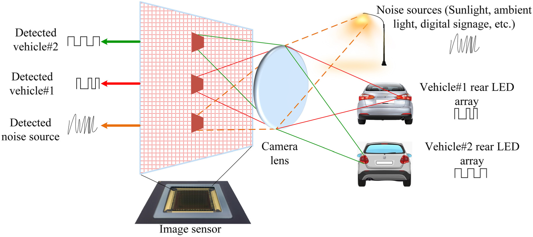
Characteristic of an image sensor.
Figure 2 illustrates the overall operation of an image sensor–based vehicular OWC system. In the general architecture of OCC systems, an image sensor or camera serves as a receiver and an LED array serves as a transmitter located on the rear side of a car or on a traffic light. In this system, more than one vehicle or other noise sources can serve as transmitters, while the image sensor serves as the receiver. In our case, the target or forward vehicles (transmitters) transmit data using their rear LED arrays. The LED arrays will transmit vehicle safety information, including traffic information, vehicle position, LED coordinates, and information about the target vehicles (e.g. speed, longitude, and latitude). Meanwhile, the image sensor (camera) receiver of the host vehicle targets the LED array and captures video frames. Then, the image sensor forms pixel arrays on the image sensor’s receiver focal plane through the imaging lens in order to determine the ROI from the captured images. Based on the captured images, the image processor can decode information from the LED arrays using multiple demodulation techniques. The decoded information is then sent to the following vehicle’s processor. Finally, the host vehicle can perform actions (e.g. reduce speed, apply brakes) using a machine learning algorithm based on the information broadcast from the LED arrays. This operation is performed repeatedly in real time to improve information accuracy and obtain more data. However, the use of an image sensor improves the optical energy considerably and enables relatively high-speed, long-distance communication. A simplified block diagram of an image sensor–based OWC system is illustrated in Figure 3, and this system uses modulation and demodulation blocks, a communication channel, and an image sensor to recover the transmitted data accurately. In the next section, the functioning of the proposed system will be explained in detail.
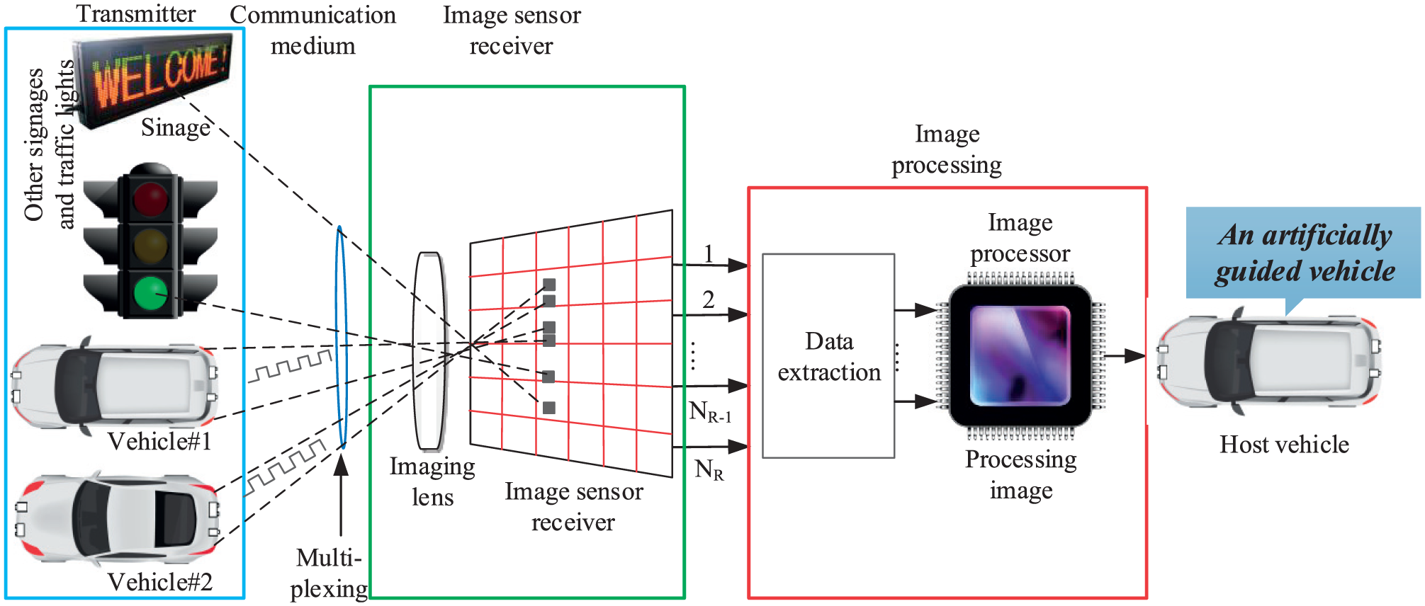
Operation of image sensor–based vehicular optical wireless communication system.

Simplified block diagram of an image sensor–based optical wireless communication (OWC) system.
One of the most important advantages of the proposed technique is that a complex processing module is not required to filter noise sources that can be completely discarded in an efficient manner as unwanted sources. A more interesting characteristic of image sensor–based OWC systems is that the communication distance does not depend on the incident light power on the image pixels. 12 In fact, distance is not affected until the image pixel size on the image sensor receiver focal plane is less than one pixel. 29 Thus, the communication distance can be increased to ensure stable communication. Although the optical communication distance can further be increased using zooming techniques, it can affect the FoV of the image sensor. Furthermore, in many cases, the proper lens type for particular applications has not yet been developed.
Interference characterization of artificial light sources
The most important interference source hampering the reception of optical signals is light reflected from multiple artificial light sources. 30 Interference from these sources can be severe in urban areas, where there are plenty of streetlights, traffic lights, and advertising billboards. These artificial light sources can be categorized in three categories. These three categories of light source have rather different electrical power spectra. First, the light sources used for lighting purposes (e.g. decoration lights, streetlights, supportive light for advertising billboards) can be fluorescent lamps, incandescent lamps, xenon lamps, and LED lamps. These are driven by alternating current (AC) source with a frequency of 60 Hz. Therefore, the frequency spectrum can be up to several kilohertz, leading to low-frequency interference. Second, light sources for static advertising purposes generally neon sign boards (i.e. neon lights) are driven by the ballasts, and their spectra extend to tens of kilohertz. Third, we have the light sources used for effective advertising and signaling, such as LED screens, and they are usually driven by sophisticated controlling circuits to display various information on the screen. Such light sources have frequency spectrum of hundreds of kilohertz and create interferences in low data rate communication. Therefore, the interferences can be minimized by modulating the LED light sources at very high frequency such as 0–1 MHz, thus improving the robustness of the system in different scenarios. Alternatively, the receiver module can adaptively discard the interferences, for example, in an image sensor–based communication system, the image sensor can remove the noise sources spatially.
Proposed scheme and modeling
In a traditional communication system, the image properties of a detected image are recovered by extracting binary values from a gray image through a simple signal or image-processing technique. Given that this involves the extraction of information from an entire image, the process can be very complex and time-consuming. In addition, such techniques cannot distinguish between LED light sources and other noise sources, such as sunlight, digital signage, and outdoor billboards, making it impossible to guarantee the extraction of required data. By contrast, our proposed image sensor–based vehicular OWC scheme can easily resolve these problems using the characteristics of an image sensor. As explained earlier, image sensors can separate communication pixels from other noise or interfering pixels. As mentioned in section “Overview of image sensor–based vehicular OWC” and shown in Figure 2, the LED array of proposed system transmits modulated data to image sensor receivers in other vehicles, which can detect the transmitting vehicle, determine the ROI, and recover broadcast information. The overall process can be summarized as follows: the LED arrays transmit data and the vision camera is used to determine the ROI of the LED array. Then, after image processing, the transmitted data are extracted at the receiver end using the high-speed camera.
Figure 4 shows the proposed system architecture; from the figure, it is apparent that the system comprises two interconnected modules: a transmission module that transmits vehicle-related information (e.g. safety and traffic information) and a receiver module that determines the ROIs of the vehicles of interest (VoI) and decodes information transmitted by the transmitter module. However, the transmitter module comprises an encoder and an LED array unit. The encoder collects various data for sending and encodes the data into packets for conveying them to the LED array unit. The LED array unit comprises an LED array (i.e. left LED array and right LED array) and LED drivers. In this system, the LEDs can be modulated at considerably high rates that are not visible to the human eye.

Image sensor–based vehicular system: (a) receiver module, (b) transmitter module, and (c) overall system architecture.
Whereas the receiver module comprises a camera receiver unit and a decoder. The camera receiver unit contains two components: (1) a vision camera-based receiver and (2) a high-frame-rate camera receiver (up to 1000 fps). The vision camera (stereo camera) detects multiple vehicles simultaneously and identifies the respective ROI of each vehicle (i.e. the backlight LED array of the vehicle). After ROI identification, the inter-vehicular distance is calculated using vision technology that will be comprehensively explained in the next part of this section. The high-frame-rate camera is used to receive the signal from the LED array. The vision and high-speed cameras should operate in a synchronized manner, with the vision camera sending updated and accurate ROI information to the high-speed camera along with distance information. Based on these data, our proposed algorithm can adapt to recent conditions of the forward vehicles and enable the high-speed camera to focus on the VoI to accurately decode the required information.
To better understand our envisioned scenarios, we have divided the functionality of proposed system into two cases: a spatial case, also called multiple vehicle or ROI detection, and a temporal case or fast processing phase. In this research, the temporal case is identified as a critical condition. Although we proposed three cases in our previous study, 15 we do not consider the general or normal vehicular scenario in this study. However, in the current spatial case, we do consider a scenario in which multiple vehicles are present and where it is necessary to detect the ROIs of multiple vehicles in order to gather information from each vehicle and to accurately detect multiple LEDs. For the temporal case, information about the forward vehicles (VoI) within a very short time frame is required in order to avoid collision. In this phase, the image is sampled faster than in the spatial case. This fast processing of a single vehicle’s information is performed using the spatial detection information, which will be discussed in the latter part of this section. Our algorithm can determine which object is closest to the host vehicle based on distance information obtained by processing multiple vehicles, and it can easily adapt to both the spatial and temporal conditions.
Spatial case (detection of vehicles and distance measurement)
The primary condition of the proposed image sensor-based vehicular communication system is the spatial condition in which multiple vehicles are present. In this case, it is necessary to process multiple vehicles in one image, where sampling or processing times are not important but the exact detection of multiple objects is crucial. Therefore, the sampling time can be greater than under the normal condition; in our study, we have considered the processing time as being 1.5 times the normal time (i.e.
Scale-space extrema detection
In this step, the interesting image feature points are categorized using difference-of-Gaussian (DoG) function. This approximation is close to the normalized Laplacian of Gaussian

where
Equation (1) is normalized into the Laplacian of Gaussian as follows

Then, the DoG map is updated in the database by computing the individual DoG value for the entire image pixels.
Keypoint localization
In next step, each pixel in the DoG map is plotted and compared with eight of its nearest points in order to determine the local extrema of DoG function,
Orientation assignment
The histograms of multiple orientations are computed based on the localized keypoints. Our selected histograms will be at least 80% higher than the maximum histogram. Finally, the unsearchable points are deleted to update the extrema orientation points.
Keypoint descriptor
In this step, the image feature points are compared with the extrema to estimate the location and determine the best matching features.
ICP
For the correction of errors, ICP algorithm adapts the extracted image feature using the SIFT algorithm. Then, a model is formed by mapping the points in a data point. The model is used to reduce the sum of square errors with the closest model points and data points. The estimated errors are considered as the sum of all errors between data points and model points. Then, rotation matrix and translation vector are developed to define the new data. In ICP method, the number of the model point should be greater than the dimension of weight matrix, and the model matrix cannot be empty. More importantly, the dimensions of both the model and the data points must be same.
After the detection of the vehicles, the relative distance between the vehicles is computed. According to the distance information, the system will decide the target vehicle from which the high-speed camera will decode the necessary safety information. To this end, the camera calibration is required to obtain an accurate position. There are many camera calibration methods.34,35 In this research, we are discussing a very simple camera calibration process, 36 where the data from a single camera calibrator (vision camera) are used to determine the translation vector and rotation matrix of the vision camera. A relationship between the camera coordinate system and world coordinate system for the vision camera can be expressed as follows

where
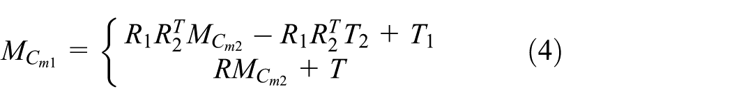
where
Figure 5 shows the ROI detection mechanism employed our system. This system uses vision cameras with the same principle as that of a mirror. Inter-vehicle distance can be measured as follows

where L is the distance between the host vehicle and the forward vehicle, D is the distance between the left and right LED array units, f is the lens focal length, n is the distance (i.e. number of pixels) between the left and right LED array units on the image, and a is the image pixel size. D (obtained from the host vehicle), f, and a are known values for any image sensors. The value of n is obtained easily using simple image-processing techniques. In this manner, the system uses both the received data and captured images to provide communication and ranging functionalities.

Mechanism for detecting the region of interest (ROI) and measuring distance.
Temporal case (critical condition)
The second condition of our proposed technique is the time-critical condition wherein upcoming vehicles or objects can cause a potential hazard are at very close distances. In this case, the sampling time consideration is crucial as collisions or accidents can occur suddenly, where more information about the targeted vehicle at a given sampling time is required. Therefore, we need to increase the sampling time to get more information in a very quick time. We have proposed a high-speed camera with a frame rate of up to 1000 fps. Therefore, the image can be processed quickly and the required information about the VoI can be decoded as much as possible within very short time. Figure 6 presents a data decoding procedure using high-speed camera in temporal condition. For temporal case, the sampling time between two frames should be faster than that in the spatial case to detect and process the VoI as fast as possible. For simplicity, in our simulation, we considered a processing time that is one-tenth the normal time (i.e.
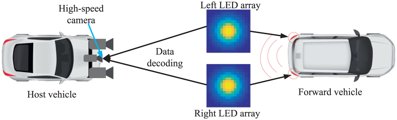
Data decoding using high-speed camera (temporal case).
In the proposed algorithm, the primary consideration is that the horizontal axis of the vehicle’s position has to be fixed with respect to the camera position so that the camera can extract a greater number of points of interest from an image under planar motion to develop a line of fixed points. In the next sampling, the camera will constitute a second pair of fixed points. The two images will intersect with each other at the same point in the image plane, although the images in different sampling time can be different in nature. Because the axes of the two images are parallel, there will be a common point at infinity where the point will intersect. Because there is one fixed point among the various views, this point can be used to determine how to perform the projective reconstruction on the image plane at infinity.

Results and discussion
To validate the proposed algorithm, we simulated our proposed scheme in MATLAB. As a consequence, Figure 7 shows the overall proposed scenario for adaptive spatial and temporal phase: Figure 7(a) represents the spatial case scenario with vision camera, and Figure 7(b) shows the temporal case scenario using a high-speed (i.e. high frame rate) camera. In spatial case, we have considered three vehicles where the sampling time of the targeted image is 1.5 times greater than the normal time (i.e.

Adaptive spatial and temporal condition of proposed vehicular communication: (a) sampling of image in spatial operation and (b) sampling of image in temporal operation.
For ROI detection, we considered first two frames of a video sequence. We took two frames (i.e. Frame 1 and Frame 2), shown side by side in Figure 8, in our simulation. The intensity images have been used to improve the processing time because it is not important to use color image for image stabilization. A large horizontal and vertical offset is visible in the figure. Correcting the error among the consecutive frames is the main objective of our proposed scheme. This is done by calibrating the camera accurately. For detecting this feature, the SIFT-ICP algorithm has been applied to a given set of point correspondences between the two frames. Given that most of the computed feature points are incorrect, a robust estimation of the geometric transform is required. For this, we applied estimateGeometricTransform function in MATLAB, which searches for the valid matching correspondences. From where it forms an affine transform which makes the first set of matching points is close enough to the second set of points. The affine transform can be expressed as a 3 × 3 matrix

where a denotes the scale, rotation, and shearing effects of the transform and t denotes the translation parameters. This transform can be used to warp the images such that their corresponding features are moved to the same image location.

Two sample frames to test the proposed algorithm.
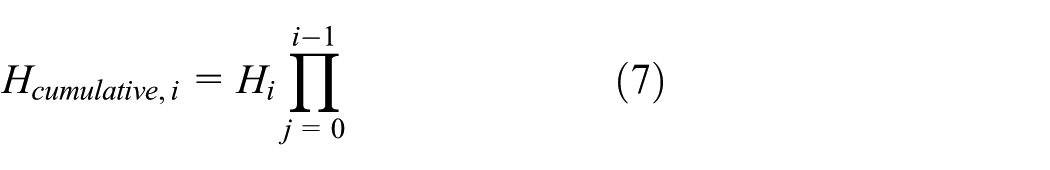
For computation, a given set of video frames Ti (i = 1, 2, 3,…, n) have been used. We have applied the proposed algorithm to estimate the error between frames Ti and Ti+1, which constitute the affine transforms, Hi. Therefore, the cumulative error of a frame i can be expressed as a product of all the previous inter-frame transforms which can be formulated as follows
Although the affine transform has six parameters, we redefined the matrix for numerical simplicity. We choose to re-fit the matrix as a simpler scale–rotation–translation transform. This new matrix (also called scale–rotation–translation transform) consists of only four parameters namely as one angle, one scale factor, and two translations, and it is given as follows
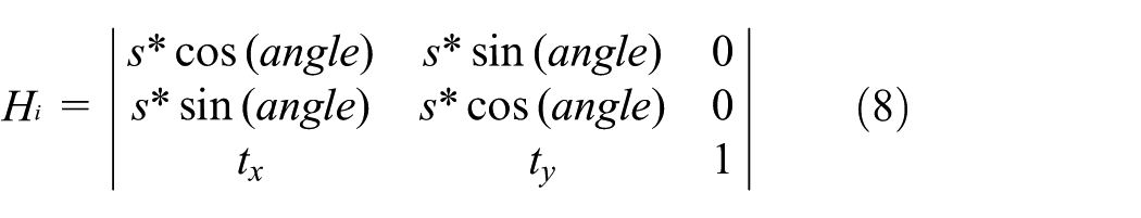
where s denotes scale, t denotes the translation parameters, and (angle) denotes the angle between the scale–rotation–translation transform.
Then, all steps were applied to the full video frame to make the sequence smooth. At each step, the H transform between the present frames was calculated. Figure 9 shows an error analysis of the video frames presented side by side (i.e. the mean of the raw video frames and of the corrected frames). The first image in Figure 9 illustrates that the original image had considerable distortion in the raw mean of the video frames. The right-side image represents the corrected frame after applying error correction method (i.e. SIFT-ICP algorithm), with almost no error. The background details have been blurred because they are not important for the vehicular condition. Finally, the results show the efficiency of our proposed algorithm to detect the vehicles and reduce errors for a stabilization system.

Error model analysis using SIFT-ICP.
Figure 10 illustrates the detailed steps involved in ROI detection using LED arrays. The first step acts as the convolution filter to determine the ROI in which light sources are possibly available. The second step aims to determine the accurate positions of LED light sources from the targeted ROI, as well as to group these light sources into pairs that belong to different VoIs. Each layer consists of two steps, specifically, convolution and ROI pooling. In convolution, also known as convolution filtering, the network attempts to label the input signal by referring to what it has learned in the past. It advantageously serves as a for being translational invariant. Hence, the pair of light sources can shift in different positions, and the SIFT algorithm would still be able to recognize the pair. In other words, in ROI pooling, the ROI is down-sampled to reduce size, which minimizes cost. The sensitivity to noise and variations is reduced by applying ROI pooling. Noisy light sources, such as streetlights without the features, can be discarded easily using this algorithm. The final ROI pooling ends when the centers of light sources are identified with the acceptable error.

Multiple ROI detection and LED array classification using SIFT-ICP.
For our simulation purposes, we applied several transformations, such as shifting the positions of light sources to coincide with the interest points, resize the image, rotate about the center, and mirror the image. Figure 11(a) compares the vehicular-lights detection performance of the general computer vision approach with the proposed SIFT-ICP approach. A computer vision-based approach processes the entire image to track LED positions, whereas an SIFT-ICP approach estimates possible positions of LEDs from previous learning and validates the correct positions from post-processing. The advantage of SIFT-ICP algorithm is that the grouping of LEDs that belong to a vehicle is simple. In addition, if the LEDs are captured as OFF states, computer vision is unable to detect the exact positions of LEDs whereas SIFT-ICP can perform the detection accurately through estimation. The accuracy of detection depends on the distance which changes linearly because the image resolution is constant. A linear classification of noisy LED states is performed to decide ON/OFF, which is considerably affected by the exposure time of the camera and an additive noise; therefore, the error rate is higher than that in our proposed approach. Our SIFT-ICP algorithm can learn nonlinear classification to satisfy achieve an mean squared error of 10−3 and 10−10 within 30 and 60 iterations, respectively, as shown in Figure 11(b).
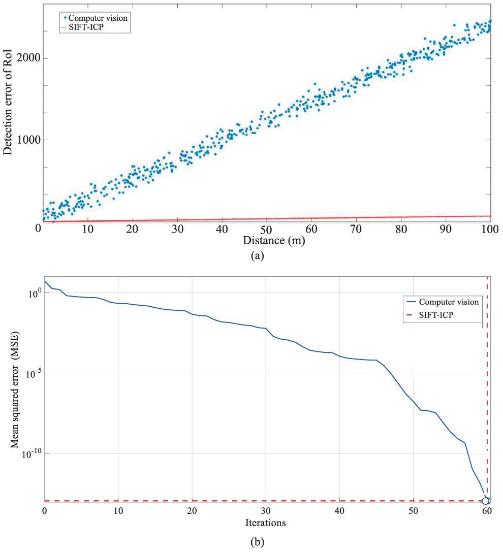
Performance analysis of ROI detection and measurement errors: (a) ROI detection error of SIFT-ICP algorithm in comparison with computer vision and (b) performance comparison of vehicular identification using ROI signaling.
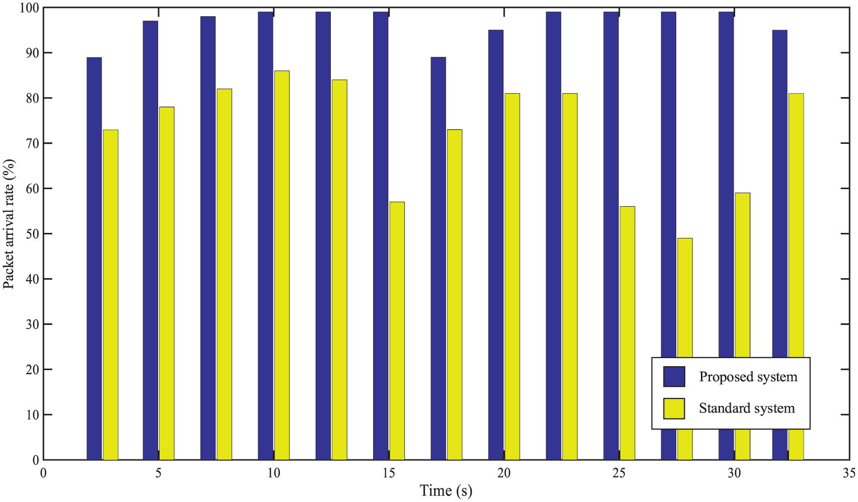
Figure 12 shows the results of packet arrival rates to decode the broadcast safety information using a high-speed camera (up to 1000 fps). The packets were transmitted from the transmitter to measure the packet arrival rate using a video. To this end, we ran the video frame for a time of 35 s and calculated the arrival rate in seconds which is represented as violet bar in Figure 12. The fluctuation of packet arrival rate happened occasionally though the worst decrease (89%) occurred two times in whole time frame. The yellow bar represents the packet rate of standard system which performance is much lower than proposed system. The failure of packet reception can happen due to the movement of forward or host vehicle on the rough road, or the LED detection error during packet receiving or waiting. Among them, movement of the vehicles on an uneven road is one of the common causes of packet losses. The packet loss can be reduced by improving the LED detection rate. Although a reduction in payload can improve the reception rate, the efficiency of data transmission will decrease due to the increase in packet overhead size.
Packet arrival rate per second in total 35 s.
Figure 13 shows the relationship of average throughput with the varying frame arrival rates when the throughput value increases rapidly from 0 to 30 fps. Its value progressed slowly when the frame arrival rate crossed 30 fps because there were many data remaining in the queue throughout the period. The throughput was almost saturated after 90 fps. However, the transmitters can only send limited packets per frame, so any increase in the frame arrival rate beyond the threshold value does not affect the throughput. The average throughput is related to data transmission rate; the higher probability of LEDs can send data, the higher the average throughput will result. The outcome from this figure is that the adaptive method enables reliable communication in noisy situations where the standard system is barely feasible. Finally, we have calculated the BER as a function of SNR of the image sensor–based vehicular communication system in comparison to standard system (Figure 14). As shown in figure, the BER performance of the standard system is inferior to that of the proposed adaptive system. The image sensor has an effect on the improvement in BER performance as it can capability to separate the light sources (LED array) from interferences or noise sources.

The average throughput of the proposed adaptive system in comparison with standard system.

BER performance comparison between proposed image sensor–based system and standard system as a function of SNR.
Conclusion
In this research, we proposed a vehicular communication system for adaptive spatial and temporal conditions using an image sensor–based VLC system. The use image sensors guarantee interference-free communication that is not sensitive to noise or interference. After investigating a few advantages of LEDs and image sensors for communication purposes, we explained the operation and functionality of the proposed image sensor–based vehicular communication technique. We then proposed a two-phase communication method by employing image sensor–based OWC communication for the spatial detection of multiple vehicles and the fast processing of target vehicle data. We proposed the use of a vision camera to detect multiple vehicles and measure inter-vehicular distance. Based on the obtained distance information, the transmitted information can be decoded using a high-speed camera. Finally, we conducted simulations to validate our proposed algorithm. The results demonstrated simultaneous detection of three objects using a vision camera while maintaining fast processing in the temporal condition using a high-speed camera. In addition, results confirmed that our algorithm could quickly adapt to changes in the conditions of communication environments. In future, we plan to implement our proposed adaptive algorithm in a real vehicular environment.
Footnotes
Handling Editor: Chunming Qiao
Declaration of conflicting interests
The author(s) declared no potential conflicts of interest with respect to the research, authorship, and/or publication of this article.
Funding
The author(s) disclosed receipt of the following financial support for the research, authorship, and/or publication of this article: This research was supported by the MSIT (Ministry of Science and ICT), Korea, under the ITRC (Information Technology Research Center) support program (IITP-2017-2016-0-00311) supervised by the IITP (Institute for Information & Communications Technology Promotion).