
Abstract
The evolution of the Internet of vehicles and growing use of mobile devices has created a demand for new wireless communication technologies. Optical camera communication, which uses light-emitting diodes as transmitters and cameras as receivers, has emerged as a promising alternative. Since light-emitting diodes and cameras are already exploring in traffic lights, vehicles, and public lightings, optical camera communication has the potential to intelligently handle transport systems. Although other technologies have been proposed or developed in both academia and industry, they are not yet mature enough to uphold the huge requirements of the Internet of vehicles. This study introduces a new intelligent Internet of vehicles system based on optical camera communication combined with convolutional neural networks. Optical camera communication is a promising candidate for maintaining interference-free and more robust communication, for supporting the Internet of vehicles. Convolutional neural network is introduced for precise detection and recognition of light-emitting diode patterns at long distances and in bad weather conditions. We propose an algorithm to detect the interested light-emitting diode signals (i.e. regions-of-interest), measure the distance using a stereo-vision technique to find out the desired targets, and simulate our proposed scheme using a MATLAB Toolbox. Thus, our system will provide great advantages for next-generation transportation systems.
Keywords
Introduction
In recent years, the number of sensor-enabled technological devices (e.g. vehicles on roads, smartphones in pockets, laptops, and tablets in offices, and TVs and music systems in homes) has significantly increased in our daily life. The universal network framework for these devices constitutes the basis of a future Internet of things (IoT), to which 25 billion “things” will one day be connected, among them a significant portion will consist of on-road vehicles. This growth will create a challenging but profitable market for the future connected vehicles. 1 As more vehicles are connected to the IoT, conventional vehicular networks are mobilizing into the Internet of vehicles (IoV). Figure 1 illustrates IoT opportunities for next-generation information and communication technology (ICT) areas.
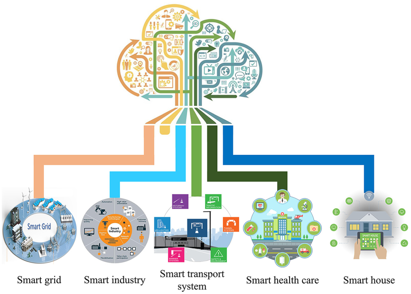
The smart IoT for ICT convergence.
The IoV represents the evolution of vehicular ad hoc networks (VANETs) for providing “smart transportation.” 2 The sole aim of conventional VANETs is to enhance traffic safety and efficiency using real-time communication that connects every vehicle into a wireless router or mobile node and, in turn, create a large network. 3 Consequently, if the vehicles move out of the VANET signal range or drop out of the network, other vehicles can join by creating a new network. However, the commercialization interests of VANETs have not been developed sufficiently, despite their huge potential for vehicular safety with low operational cost. 4 VANETs have also limitation in connecting number of vehicles and mobility support because they cover very small areas and cannot provide the global positioning services for the desired applications. With safety being the prime goal in the continuous modernization of vehicles and road infrastructures, growing traffic casualties in recent years have become a serious concern. Thus, reliable cooperative vehicular communication can introduce a new era in road safety by reducing traffic casualties. 5
To avoid collisions and accidents with vehicles, information from the surrounding vehicles and infrastructure is necessary for highly accurate and precise localization, as well as maintaining communications. The very first technologies developed for sensing objects were radar and ultrasound. Those two techniques were first used outside of cars for parking assistance and have enabled the adoption of automated parking. These technologies can also be used for collision avoidance (e.g. detection of pedestrians, animals, and other vehicles). Alternatively, the global positioning system (GPS) has a long positioning range, 6 but cannot provide orientation information about the surrounding vehicles or infrastructures. Also, GPS is not a reliable positioning technique in the vehicular environment because localization is not accurate enough to discriminate between vehicles on different driving lanes. Its accuracy can also be hampered by signal blockage in tunnels, urban canyons, or dense trees. In addition to GPS, other localization technologies, such as light-emitting-diode detection and ranging (LEDDAR) and light detection and ranging (LiDAR), which are mainly based on lasers, have been proposed for positioning or ranging applications. In general, LiDAR uses light pulses from a laser source and works on the principle of time of flight (ToF). 7 LiDAR can be used as an alternative approach for measuring lane and vehicle heading angles indoors; however, it offers less accuracy compared with inertial navigation systems. 8 Unfortunately, LiDAR is harmful to humans, very expensive, and often very heavy; the cost of the LiDAR system can sometimes be more than that of the vehicle. More importantly, it does not include any communication mechanism with the surrounding vehicles or infrastructures. Thus, there is a real need for an optical-identification system that can directly deliver localized identification of vehicles. So, the development of next-generation intelligent autonomous vehicles and intelligent transportation systems (ITS) is crucial.
The optical spectrum can serve as a good resource for wide-band wireless communications. Optical wireless communications (OWC) are attractive for next-generation communication due to their applications to different emerging services. There are two main advantages to OWC: the potential large-transmission bandwidth due to the high-frequency carrier and communication security from the lack of radio-frequency (RF) radiation. Applications of this technology include three-dimensional (3D) localization, kinetic camera-based ranging or distance measurements, various intelligent applications (e.g. virtual or augmented reality), digital or display-signage applications 9 and, more importantly, autonomous vehicular applications.10,11 OWC operates in three spectrum bands: infrared, visible, and ultra-violet. Daily OWC applications, which typically use the visible light spectrum, are also known as visible light communication (VLC) and can be achieved using LEDs as transmitters and photodiodes (PDs) or avalanche photodiodes (APDs) as receivers. VLC is mainly used in indoor environments for applications such as handheld terminals, robots, and intelligent furniture and appliances. Because light-emitting-diode (LED)-based VLC signals are non-coherent, intensity-modulation or direct-detection (IM/DD)-communication signal processing has been adopted.
OWC can also provide cooperative vehicle positioning using image sensor as receivers and LEDs. Communication between LEDs and cameras has been developed as optical camera communication (OCC). 12 Recently, cameras with visible light have been integrated into autonomous vehicles for several applications including backup cameras, road-sign detection, roadside-LED detection, blind-spot detection, lane-departure monitoring, other-vehicle detection, and distance measurements from vehicles, infrastructure, or objects (using ToF or stereo-vision systems). Therefore, on the way toward autonomous evolution, it is important to develop not only the hardware but also the intelligence necessary to process the data and assist the entire system in making safe decisions. The application of OCC technology to autonomous systems is an attractive area for researchers and companies and will ensure an intelligent advanced-driver-assistance system in automotive environments.
In vehicular OCC systems, LEDs are used to transmit internal vehicle information such as longitude, latitude, and speed to nearby vehicles or roadside stations or to broadcast safety information, while image sensors are used to receive LED-transmitted information and various algorithms are used to decode information relayed by the LEDs. In vehicles, cameras are being introduced for tasks such as monitoring driver drowsiness; adaptive cruise control; collision detection and avoidance; traffic sign and object recognition; and intelligent speed adaptation. Although studies on the capabilities, potential, and advantages of OCC systems have recently been conducted, only a few of these studies have assessed the actual implementation of the OCC system in a real automotive environment, and their reliability must be improved before implementing these systems. Recently, automotive vehicular communication is using wireless access in vehicular environments (WAVE), that is, IEEE 802.11p standard. But our proposed OCC system has several advantages over IEEE 802.15.11p as listed below:
Multiple-input multiple-output (MIMO) facilities;
Unlicensed spectrum;
Huge frequency band;
Ranging and communication at the same time;
Base station independent (i.e. In OCC, it is not required to communicate with the base station for communication, vehicle or object detection, ranging, and localization);
In OCC, vehicle broadcasting their own information (i.e. position information, emergency information, traffic information, and road condition). The host vehicle can either receive data from forwarding vehicle or discard to receive data. It is not mandatory for handshaking communication between two vehicles. 13
A comparison table of OCC with IEEE 802.11p is presented in Table 1.
Comparison of OCC over IEEE 802.11p.

OCC: optical camera communication; WAVE: wireless access in vehicular environment.
Most ongoing research on autonomous localization and simultaneous vehicle-to-vehicle (V2V) and vehicle-to-infrastructure (V2I) communication is based on visible light,11,14 which has a short localization range (up to 10 m) without using a high-speed camera (which is very expensive). In Guo and colleagues,15,16 automated driving control system has been proposed for dynamic steering and braking control using vision algorithms. They provided the relative location between the autonomous vehicle to the reference path as well as detection of the desired path using five stages. Unfortunately, these approaches cannot provide reliable communication due to interference from various sources, such as sunlight or bad weather (fog, rain, or smoke). Vision-based systems are mainly depended on cameras which are affected by interferences. No such research has been conducted for avoiding these sources of interferences. In this study, we propose a convolution neural network (CNN) in conjunction with OCC to allow receipt of information in bad weather conditions. CNNs can easily be used for classification and recognition of LED patterns. Furthermore, CNN can decode the LED data even at an unclear state where LED patterns are not clearly visible due to signal blockage by other vehicles or bad weather condition. The main advantage of the CNN system is the image resolution and resulting superior interface with the driver, providing an easier image to decrypt and understand.
In this study, we have combined the OCC system with CNN to provide IoV functionality, which will ensure long-range identification, will remain reliable during bad weather, and will not be vulnerable to partial occultation. Two key elements are necessary to recognize LED signals based on OCC technology in ITS applications: (1) the feasibility of OCC for outdoor conditions and under constraints posed mainly by ambient noise and daylight; (2) the capability of this technology to detect vehicles accurately and to satisfy vehicular safety requirements. This article makes the following contributions:
We have developed an image sensor–based OWC system for vehicles using the rear LED arrays of cars as the transmitter and an image sensor (camera) as receiver.
We have introduced CNN to accurately identify the LED patterns and to detect this pattern even at long distances, under bad weather conditions, and with signal blockage.
We have evaluated the performance of the OCC system for inter-vehicle communication under daylight conditions and for line-of-sight (LOS) scenarios using a MATLAB simulation model.
Our proposed system will ensure several significant parameters of the IoV system including data rate, communication range, mobility support, minimum communication delay, and scalability.
The remainder of this article is organized as follows. Section “Internet of vehicles” identifies the requirements for the OCC-based IoV system for automotive vehicular applications. Section “Architecture optical vehicular communication” introduces our OCC system architecture, giving the details of the transmitter, receiver, and channel model. In section “Proposed scheme,” we present our proposed system along with detailed CNN algorithms. Then, the evaluation of our proposed system using MATLAB simulation tools is presented in section “Results and discussion.” Section “Conclusion” concludes our article.
Internet of vehicles
Conventional VANETs
In the modern world, the number of vehicles and vehicle-assisting infrastructures are increasing rapidly, making the transportation system more vulnerable than ever. This results in more traffic congestion, road casualties, and accidents. To deal with the complexity of the current traffic system, we need a unique network to accumulate vehicular-system information and ensure an effective transportation system such as VANET, 17 thus providing proficient communication on the road with the help of pre-established infrastructure. Generally, VANETs connect all vehicles and infrastructure within their coverage area through a wireless router or wireless access point (WAP). The connection between the vehicle and the network can be lost when a vehicle moves out of the signal range of the network. Consequently, a new free WAP is generated in the existing VANET for other vehicles outside the network. Improving traffic safety and enhancing traffic efficiency by reducing journey time, cost, and pollution are two major reasons behind the demand for VANETs.
Despite creating greater opportunity in the transportation system at lower operational cost, 4 VANETs suffer from various drawbacks such as a lack of pure ad hoc-network architecture, 18 incompatibility with personal devices, 19 unreliable Internet service, 20 lower service accuracy, unavailability of cloud computing, 21 and cooperative operational dependency of the network. Concurrently, there have a limited number of access points for particular networks. A few countries (e.g. the United States and Japan) have tried to implement the basic VANET architecture but not the entire system due to poor scope for commercialization. This leads to demand for more reliable and market-oriented architecture for modern transportation systems. 5 IoV can be a good candidate to meet the challenges of VANETs, such as the commercialization problems and growing traffic casualties. Moreover, the IoV will ensure a huge profitable market for “connected vehicles” in the future. 1
Overview of the IoV
The IoV is an integral part of the IoT, which connects various heterogeneous networks, for example, inter- and intra-vehicle networks with the Internet. 2 This heterogeneous network architecture can be categorized into five types of vehicular communication: vehicle-to-vehicle (V2V), vehicle-to-infrastructure (V2I), vehicle-to-roadside unit (V2R), vehicle-to-sensors (V2S), and vehicle-to-pedestrians (V2P) as shown in Figure 2. It is anticipated that enhanced traffic safety, improved traffic efficiency, and implementation of supervision and control can be assured by the IoV (e.g. information exchange through inter-vehicle communications and real-time broadcasting of traffic conditions to data centers22,23). Its purpose is to ensure that devices can communicate with each other and exchange information with intelligence. Moreover, the research and development of IoV technologies will integrate automotive and information technologies together.

The five types of vehicular communications of IoV.
Although many researchers and industries have proposed the IoV for various purposes,24,25 use of this concept is still in its initial stage. Many countries have already implemented or proposed some basic IoV services. The United States has installed security chips in vehicles to store identifying information about every vehicle in their data center. 26 The government of India has also brought its vehicles into a single network through GPS and wireless fidelity (Wi-Fi). 27 A new next-generation transportation system, the cooperative intelligent transportation system (C-ITS), has been initiated by the European Commission. 28 Korea and Australia are also interested in implementing such automotive vehicular systems. 29 Moreover, both Google and Apple are developing a smartphone-based connected-driving system; Apple has developed a system called “CarPlay,” with a voice-support feature to allow the driver to use iPhone services through the display of their car. 30 All these efforts are initial steps toward the design and development of the IoV.
Lack of coordination and communication is the biggest challenge facing IoV implementation. Lack of standards also makes effective V2V communication and usages more difficult. Thus, the challenges start with ensuring safety, convenient and cooperative communication, energy-savings, and simple implementation. Large concentrations of vehicles, lighting systems, or drones can also stretch the existing RF or ad hoc computational resources to their limits. Thus, it is of great interest to the ITS field to develop new solutions that complement RF or other ad hoc networks. Efforts should be made to develop and enhance these new platforms, which will enable analytic and semantic processing of data from vehicles. OCC can be a better candidate for cooperative vehicular communication, enhancing driving safety, ITS, collision warning, and pedestrian detection, as well as providing range estimates for nearby vehicles. OCC is a new technology (i.e. a development of OWC) that works on the same principle of OWC. OCC uses LEDs as transmitters and cameras as receivers instead of PD in the case of OWC. We will discuss the benefits of OCC-based V2V or V2X communication in detail in the next section.
Architecture optical vehicular communication
Over the past few years, there have been many advances in camera-based applications and services, such as multimedia, security tracking, localization, broadcasting, 9 and ITS.10,14 Image sensors can build images pixels projected from various light sources within their field of view (FOV). Most of the relevant researches have focused on the performances of visual communication systems based on imaging or non-imaging techniques. OWC using image sensor, known as OCC, is a promising technology combining the functionality of LOS service and LED illumination. In the general architecture of OCC systems, a camera functions as the receiver and an LED array functions as a transmitter located on the rear side of a vehicle or on a traffic light (see Figure 3). Since the image sensor has unique characteristics, OCC systems have several advantages over existing wireless communication technologies (i.e. single-element PDs or radio waves).31,32 As shown in Figure 3, the data transmitted from two different LED transmitters (Vehicle#1 and Vehicle#2 rear LED arrays) can easily be captured and distinguished simultaneously using an image sensor. Background-noise sources (e.g. sunlight, ambient light, and digital signage) can also be discarded by removing the pixels associated with those sources. In this manner, the image sensor can provide secure, interference-free, and reliable communications, even in outdoor conditions.

Operation of image sensor–based optical vehicular communication.
Figure 3 illustrates the overall operation of an image sensor–based optical vehicular communication system. In this system, more than one vehicle or other light (noise) sources can serve as transmitters, while the image sensor serves as the receiver. In our case, the target or forward vehicles (transmitters) transmit data using their rear LED arrays. The LED arrays will transmit vehicular safety information, including traffic information, vehicle position, LED coordinates, and information about the target vehicles (e.g. speed, longitude, and latitude). Meanwhile, the image sensor receiver of the host vehicle targets the LED array and captures video frames. Then, the image sensor forms pixel arrays on its focal plane through the imaging lens in order to determine the region-of-interest (RoI) from the captured images. Based on the captured images, the image processor can decode information from the LED arrays using multiple demodulation techniques. The decoded information is then sent to the following vehicle’s processor. Finally, the host vehicle can perform actions (e.g. reduce speed and apply brakes) based on the broadcasting information from the LED arrays using a machine learning algorithm. This operation is performed repeatedly in real time to improve information accuracy and obtain more data. However, the use of an image sensor improves the optical energy considerably and enables relatively high-speed, long-distance communication.
In this study, we have proposed a novel technique for implementing the IoV using OCC. We transmit emergency information from the vehicles through LEDs, and cameras receive the transmitted LED signals to maintain communication between the vehicles. The modulated signals from the LEDs are not visible to the human eye, but the signal can be detected by any normal cameras. The technique can also be used in the road environment both during in day time and night time while maintaining communication functionality. The transmitter and receiver of the proposed system are explained in this section, together with the channel modeling.
Transmitter
The transmitter unit is composed of an optical LED source (typically using semiconductor laser diodes or high-power LEDs with beam collimators), a modulator, an optical amplifier (if required), beam-forming optics, driving circuits, and a controller to control the source of data streaming as illustrated in Figure 4. Before modulating the signal from the transmitter end, the data from the vehicles are accumulated, and channel coding (e.g. low-density parity-check) is used to mitigate intensity fluctuations in the received signal. A spatial-2-phase-shift keying (S2-PSK) 14 modulation scheme is used to modulate the light signals, which are then intensified by an optical amplifier. S2-PSK-modulated signals are more robust and more perceptible to a vision sensor compared with spatially coded signals, which are vulnerable to both partial occultation and vision sensor resolution. To make the light signals safer for human eyes, we limit the average and peak transmission powers of the optical source.

Block diagram of the OCC transmitter.
Receiver
A typical OCC system is shown in Figure 5. The receiver is composed of a high-frequency, low-resolution camera equipped with a bandpass filter and a decoding algorithm. The OCC system based on IEEE 802.15.7m aims to use image sensor and/or a camera as the receiver. In the OCC receiver, typical regime is undersampled. The camera comprises an imaging lens, image sensor, and readout circuit. The camera captures the image of the road environment, and the algorithm decodes the signal from the emitters. The imaging lens projects light onto the image sensor. The signal received by this process can be viewed as individual pixel across image sensor. At the same time, each pixel is connected to a trans-impedance circuit, which converts each activated pixel into a voltage determined by the transmission rate, the dynamic range of the converted electrical signal, the thermal noise generated by the receiver, and the impedance matching with other receiver parts. In its turn, the circuit converts the pixel voltage into binary data. Cameras can be split into two categories based on the pixel exposure, namely, the global shutter and the rolling shutter categories. Global shutter cameras generally used charge-coupled-device image sensors and exposed all pixels per frame simultaneously. Rolling shutter cameras employ complementary metal oxide semiconductor (CMOS) image sensors which scan pixels sequentially. Note that CMOS imagers with global shutter have already been developed and are available commercially. However, they have not yet been used in smart devices.

Block diagram of the OCC receiver.
Channel model
OCC channel characteristics are defined mainly by the physical characteristics of transmitter and receiver. We consider additive white Gaussian noise (AWGN) in the communication channel between the transmitter and the receiver. The received signal at the image sensor is given by equation (1)

where ha is a random variable (representing the channel state), R is the detector responsivity, x is the binary transmitted signal intensity, and n is the AWGN with variance,

where Pt is the average optical transmitted power such that values of
The SNR is considered as the most common performance measure for any digital communication system. The probability distribution function (PDF) of the SNR can be derived as follows

where

Interference characterization of artificial light sources
The most important interference source in the reception of optical signals is light reflected from multiple artificial light sources. 34 Interference from these sources can be severe in urban areas with a high density of modern facilities, such as street lights, traffic lights, and advertising boards. Artificial light sources can be grouped into three categories, which exhibit distinct electrical-power spectra. First, light sources used for lighting (e.g. decorative lights, street lights, and advertising billboards); these can be fluorescent, incandescent, xenon, or LED lamps and are driven by AC sources with a frequency of 60 Hz; they have frequency spectra up to several kHz, causing low-frequency interference. Second, light sources for static-advertising, such as neon signs (i.e. neon light) are driven by ballast with spectra extending to tens of kHz. The final category includes the light sources used for effective advertising and signaling, such as LED screens, which are usually driven by sophisticated control circuits to display a variety of information on the screen. These light sources create interferences in low-data-rate communication and have frequency spectra of hundreds of kHz. Thus, interference can be minimized by modulating the LED light sources at very high frequencies (i.e. 0–1 MHz), thus improving the robustness of the system in different scenarios, or the receiver module can adaptively discard sources of the interferences. For example, in image sensor–based communication systems, image sensors can spatially remove noise sources.
Proposed scheme
Our proposed intelligent IoV system comprises three main forms of communications: V2V, V2I, and vehicle-to-cloud (V2C). Figure 6 presents an overview of the proposed system based on OCC. LED signals and a camera are used as a transmitter and a receiver, respectively, for V2V and V2I communication. In V2C communication, cellular technology can be used to uphold the connection between the Internet (e.g. cloud or database) and the vehicles or infrastructures. The vehicles in V2V are defined as forward vehicle and following vehicle. First, the forward vehicle transmits the information and the following vehicle receives the information. The vehicles can also receive traffic information (e.g. certain emergency information, traffic condition, safety information, and accident information) from traffic lights. The forward vehicle uses its tail-light LEDs to transmit information toward the following vehicle using S2-PSK modulation scheme. The following vehicle uses CNNs to decode the information from the forward vehicle.
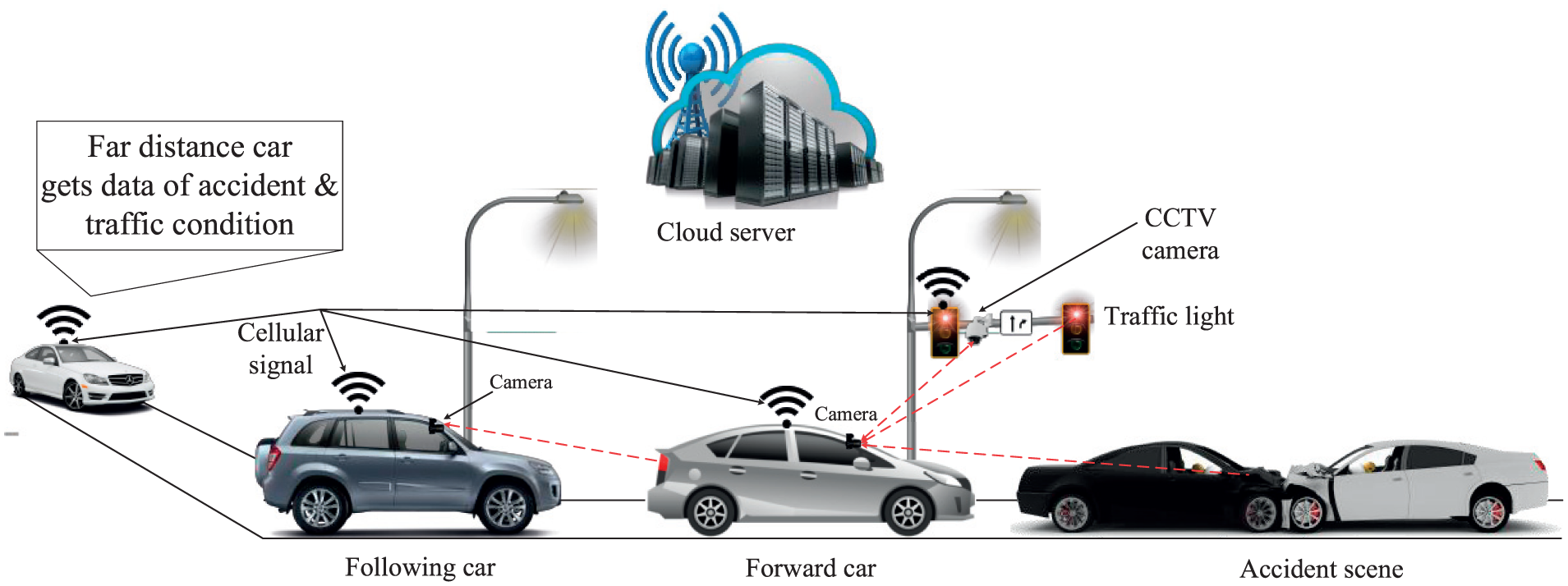
Proposed system architecture for an intelligent IoV.
In V2C, both forward and following vehicles can share information using cellular technology toward a cloud server. After receiving information from the vehicles, the cloud server will process the information using a centralized controller (e.g. Software-defined networking (SDN)-based OpenFlow 35 ) and broadcast this information back to the IoV network (i.e. vehicles or traffic lights) through cellular communication. This information can be useful for the vehicles that are far away from the incident.
In the remainder of this section, we have described our proposed IoV model in more detail. The proposed system employs a multi-criterion application in the following four phases: (1) detection of LED signal, (2) target achievement, (3) LED-array pattern detection and recognition using CNN, and (4) broadcast information using a central server.
Detection of LED signal
The aim of this step is to recognize vehicle LED lights or traffic lights using a camera receiver that captures the entire scene within its FOV. We have considered a scenario wherein a vehicle is moving down a road and is identifying other vehicles or infrastructures with LED-optical signals. In OCC systems, on the transmitter side, the LEDs emit light, and the intensity of LED lights is detected by the camera at the receiving end. The emitted signals from transmitters can be detected using an IM/DD technique that passes through any point between the transmitter and receiver. For data transmission in OCC, various modulations (such as frequency shift keying (FSK), PSK, and OOK) have been proposed by the IEEE 802.15.7m standard. 36 Here, we have considered the S2-PSK modulation scheme; 14 an image sensor mounted on a vehicle can detect S2-PSK modulated signals.
An overview of the LED signal (RoI) detection process from the image is shown in Figure 7. As indicated in the figure, the following vehicle captures an image of a road scenario at night. The captured images contain not only the LED light sources but also the reflected lights from various surfaces that are not related to the IoV infrastructure. To detect absolute optical signals, high-intensity values in the captured image will be extracted using an image-acquisition process. In general, the height of the light sources in the road infrastructure is several meters away from the traffic lights depending on the surface of the road. Thus, it is expedient to differentiate between traffic lights and the lights used for road decoration or lighting.

Multiple RoI detection to remove interference from light sources.
After the intensity-filtering process, differential images are determined from two consecutive captured images and the differential images are stored for further processing. The differential images help to recognize the changes between adjacent images. Therefore, the actual LED signal can easily be distinguished from noise sources in the differential images. Here, the LED light sources blink with S2-PSK modulation which represents two phases “0°” and “180°.” Then, the resulting image is binarized to extract the LED signaling features from the captured images.
In summary, the identification algorithm processes the input images to extract the corresponding LED region from the emitters. Other light sources (sunlight and advertising boards) are discarded through shape analysis. The entire identification algorithm can be summarized as follows:
The camera acquires the filtered images in which the emitters appear as bright spots.
To keep the brightest pixels (LEDs) in the scene, the received image is binarized using a threshold value.
The LED regions are made more consistent, bright, and less fragmented, using morphological dilation.
The regions to be accepted or rejected will mainly depend on the size and shape of the detected regions. For example, large regions (corresponding to the sky), regions which do not look like a spot, (such as pieces of vegetation, LED signage, and advertising boards), and regions with small spots (i.e. reflection from other light sources) are rejected. The algorithm used to determine the shape of a region calculates the rate of pixels of the detected region inside its circumcircle.
The accepted spots are termed as RoIs or targets.
Target achievement
After identifying the LED light sources (RoIs) on the image plane, the risk factor of action taken by surrounding vehicles is determined (also called finding the temporal and spatial condition of a vehicle). For this case, we have to measure the distance from the captured image as distance information can help to make decisions. Based on the information, we can easily understand which object is important and where it is not necessary to pay attention. All incidents that happen in the real world can be described in three dimensions (3D), but the camera generates only two-dimensional (2D) images. Thus, we need to adapt a convention algorithm to measure the distance from a 2D image. There are various approaches measuring depths from images; the most recent trend is to use a stereo-vision camera, rather than a single camera, in a manner analogous to our own vision system. 37 A stereo-vision camera comprises two cameras mounted at a fixed position on a single apparatus for (1) synchronizing the focal point and (2) adjusting the image-focal plane of both cameras. Both cameras capture the same scene but with a slightly shifted FOV, forming a stereo image pair. 38 Distance measurement relies on matching the pixels in the left and right images. 39 The following algorithm is used to complete the task:
Image acquisition (i.e. input image from both left and right cameras).
Image rectification to horizontally align the epipolar line of the two images using linear transformation.
Segmentation for detection, recognition, and measurement of objects in the images.
Stereo matching algorithms for depth calculation. Several algorithms are used for stereo matching, such as sum of absolute differences (SAD), correlation, normalized cross correlation (NCC), and sum of squared differences (SSD).40,41 The SAD algorithm computes the intensity differences for each center pixel (i, j) in a window W(x, y)
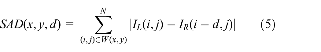
where
Depth map estimation. For stereo cameras with parallel optical axes (see Figure 8), focal length f, baseline b, and corresponding image points (xl, yl) and (xr, yr), the coordinates of a 3D point
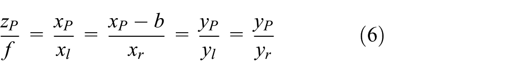


Distance calculation using (a) stereo image from a stereo camera and (b) system platform algorithm.
The depth is calculated from the disparity map using the rectified image from the stereo camera. The disparity map (equation (9)) is the difference between the x-coordinate of the projected 3D coordinate, xP, onto the left camera image plane and x-coordinate of the projection onto the right image plane. Therefore, disparity can be calculated from the following equation


LED-array pattern detection and recognition using a CNN
After obtaining the distance information from the target achievement stage, the information from the targeted vehicles is decoded. Here, we have used a CNN to recognize LED patterns. For instance, if the targeted vehicles are at a long distance or LED signals are blocked due to bad weather conditions, other vehicles and infrastructure, it will be difficult to decode the pattern of the LEDs. Although neural networks (NN) and other pattern-recognition algorithms have been developed over the past 50 years, CNNs have developed significantly in recent years. CNNs are being used in a variety of areas, such as image and pattern recognition, natural-language processing, speech recognition, and video analysis. The improved network structures of CNNs lead to memory savings and reduced computational complexity and, at the same time, offers better performance for numerous applications.
Moreover, CNN is robust against distortions, such as different lighting conditions, change in shape due to the camera lens, presence of partial occlusions, and horizontal and vertical shifts. In the conventional case, using a fully connected layer to extract the features, an input image of size 32 × 32 and a hidden layer having 1000 features will require on the order of 106 coefficients, which requires a huge memory. In the CNN layer, the same coefficients are used across different locations in space, so the memory requirement is drastically reduced. In addition, in standard NN, the number of parameters is much higher, which increases the training time proportionately. Assuming perfect training, we can design a standard NN whose performance is the same as a CNN. However, in practical training, a standard NN equivalent to a CNN would have more parameters, which would lead to more noise during the training process. As a result, the performance of a standard NN will always be worse than the equivalent CNN.
Figure 9 shows a typical CNN algorithm for detection and recognition, which comprises four stages: (1) pre-processing of the image, (2) detecting the RoI, (3) object recognition, and (4) decision-making. The first step contains the outside data, which can be used for training, particularly the camera parameters. The decision-making step works on the recognized objects. Sometimes, it may make complex decisions, but the algorithm operates on limited data such that so the decisions are not usually computationally difficult or memory intensive. However, CNNs are now having a wide impact on object detection and recognition stages, which are among the most difficult challenges in the field. Figure 10 shows a visualization of the CNN algorithm for vehicle LED pattern detection and recognition.
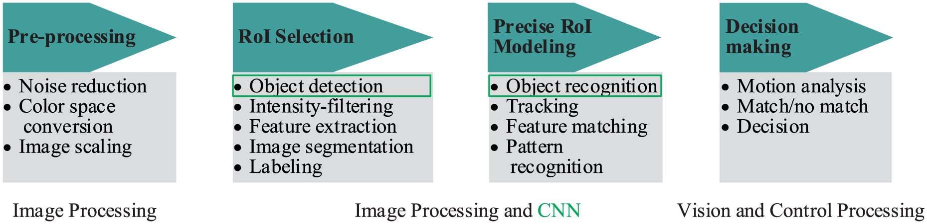
Typical CNN algorithm for detection and recognition.

CNN-based LED pattern classification and recognition.
Figure 11 shows the operation of LED-state detection using CNN, in this case, where the signal has been blocked by another vehicle. In our system, we use CNN to classify the LED region instead of classifying the entire image, reducing computational cost and total computational time. To better understand our proposed CNN system, we have categorized it into four steps, namely, design of a CNN, configuration of training options, training a faster CNN object detector, and evaluating the trained detector.

Decoding of LED data using CNN in an unclear state.
Designing a CNN
A CNN is composed of a series of layers, wherein each layer describes a specific function. For example, imageInputLayer is the image-input layer, convolutional2dLayer is the 2D convolution layer, reluLayer is the rectified linear unit (ReLU) layer, maxPooling2dLayer is the max pooling layer, fullyConnectedLayer is the fully connected layer, and classificationLayer is the classification and recognition of output layer for an NN. The MATLAB Neural Network ToolboxTM provides the required functionalities to design the CNN layer by layer. The first step is to design the input layer, which defines the type and size of the imageInputLayer function. The input size varies for different purposes. For classification tasks, the input size is typically the same size as the training images. However, for detection or recognition tasks, the CNN needs to analyze smaller parts (i.e. the LED region) of the image, so the input size must be at least the size of the smallest object in the data set. In this case, the CNN is used to process a [32*32]-RGB image.
The middle layers of the network consist of convolutional repetitive blocks, ReLU, and pooling layers, which are the core part of the CNN. The convolutional layers are a set of filter weights, which are updated during network training; the ReLU layer adds non-linear functions to the network, which map image pixels to the semantic content of the image; and the pooling layers downsample data as they flow through the network. We can create a deeper network by repeating these basic layers, but to avoid downsampling of data too early, pooling layers should be used cautiously. Important information for learning can be discarded due to early downsampling. The final layers are typically composed of fully connected layers. At this point, the network must produce outputs that can be used to measure whether the input image belongs to one of the object classes or the background. Finally, we combine the three layers. Then, the weights of the first convolutional layer are initialized with a standard deviation of 0.0001, which improves the convergence of training.
Configure training options
The training of the CNN can be split into four categories. In the first two categories, the region-proposal and region-detection networks are trained. The final two categories combine the networks from the first two steps into a single network. 42 As each training category may have a different convergence rate, each category should be set with independent training options. We can specify the network-training options using the trainingOptions function of the Neural Network ToolboxTM. In this case, we have set the learning rate for the first two steps higher than for the last two steps, such that the weights can be modified more slowly in the last two steps for fine tuning. The greatest advantage of this method is that we can resume training from a previously saved point even if training is interrupted due to power outage or system failure.
Training a CNN LED pattern-recognition detector
After specifying the CNN training options, we need to train the LED pattern detector. The inputs of this detector are the pre-trained network and the training options. The training function can form a new network by automatically modifying the original trained network. The image patterns (i.e. LED patterns) are extracted from the training data during this process. The patterns required for training are defined by PositiveOverlapRange and NegativeOverlapRange. Positive training samples overlap by 0.6–1.0, whereas negative training samples overlap by 0–0.3. The optimal values for the positive–negative pairs should be chosen based on the testing value of the training detector.
To accelerate CNN training and reduce the training time, the use of a parallel pool is highly recommended for MATLAB users. But the parallel pool should be enabled prior to training. For efficient computation competence, a graphics processing unit of 3.0 or higher is strongly recommended. To save execution time, a pre-trained network can be loaded from a disk. If one wishes to train the network oneself, one must set the doTraining variable manually.
Evaluating the detector using a test set
To verify the training, we should investigate the detector’s response to for a test image. The primary step for detector performance evaluation is to run the detector on a test image set. To ensure a short evaluation time, the results are loaded from a previously saved disk. For this, we have set the doTraining function from the previous section to execute the evaluation locally. To evaluate the detector effectively, we recommend testing larger image sets. We can measure common performance metrics using object-detector-evaluation functions, which are supported by the MATLAB Computer Vision System ToolboxTM; for example, log-average miss rates can be found using the evaluateDetectionMissRate function and average precision can be found using the evaluateDetectionPrecision function.
Broadcast information using a central server
In our proposed scheme, we have introduced the concept of using a cloud server or database for non-line-of-sight (NLOS) communication. After receiving the information from the CNN, we can broadcast emergency information (e.g. accidents or traffic condition) to the cloud server in order to support communication with distant vehicles. Suppose an emergency condition (e.g. accident) has occurred far up the road from the host vehicle (e.g. 5 km). If the remote vehicles can get this information instantly, it would be easy to change their route according to the following traffic conditions. However, to broadcast this information to the remote vehicles instantly using OCC-based V2V communication, it will be time-consuming to reach long distances (e.g. 5 km). Thus, in this case, OCC-based communication will not be effective. Consequently, we have proposed cloud-based vehicular communication over long distances.
In V2C communication, vehicles at the incident can receive the information from forward vehicles using their respective cameras. Then, the processing system mounted on the vehicles will transmit the emergency information to the cloud server using cellular networks. After receiving information from the vehicles, the cloud server will process the information using a centralized controller (e.g. SDN-based OpenFlow 35 ) and broadcast the information back to the IoV networks based on the priority of the incident to all connected links through cellular technology. After receiving the information from the server, the vehicles or traffic lights will transmit that information through LED lights to subsequent following vehicles, allowing them to change direction or take other actions to reach their destinations based on the situation. However, this is outside the scope of this article.
Results and discussion
The first part of our proposed algorithm is to detect the RoI (i.e. the LED region in the image). For this, we have used a real road video to detect RoIs on the image plane. Figure 12(a) shows an image frame of our time-lapse video, and Figure 12(b) represents the detected RoIs on the image plane after applying our algorithm. In this case, we have extracted the LED regions using differential images and then binarizing the resulting image using RGB thresholding. In the figure, the detected RoI with red rectangular markings represents the nearest vehicle, the green rectangular markings represent far-distant vehicles, and the yellow rectangular markings represent the signals from traffic lights. Figure 12(c) and (d) show 3D representations of the original and optimized constellations of the threshold image at the receiver. The optimized constellation points in 3D color space are distributed more uniformly than the un-optimized or original points in 3D color space. This implies that most of the constellation points are closer to the threshold value, which proves the high efficiency of our proposed algorithm. But there may have a few abnormal constellation points away from the threshold constellation points, which can be ignored.
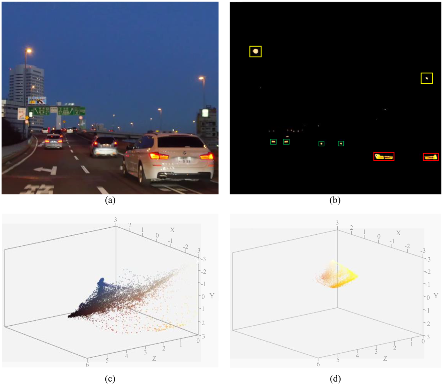
(a) Original image, (b) successful detection of LED signals (i.e. RoI), and 3D thresholding of the image at the receiver end (c) before optimization and (d) after optimization.
After detecting the RoIs, we must decode the vehicle information. For this case, we follow two consecutive processes: (1) distance measurement and (2) LED-array pattern detection. For distance measurement, we use the stereo camera approach and the MATLAB stereo camera calibrator app. Figure 13(a) shows the visualization of the extrinsic parameters of the camera in the 3D-image plane. In order to compute the disparity map and construct the 3D scene, the image frames from both cameras should be rectified. Figure 13(b) shows the rectified image of the video frames, which are row-aligned. This simplifies the computation of the disparity map by reducing the search space for matching points to one dimension. The rectified images can be viewed using stereo red–cyan glasses, combining them into an anaglyph to obtain the 3D view.

(a) Extrinsic parameter visualization of camera calibration process and (b) rectified image of the video frame in the3D-image plane.
Figure 14 shows the disparity map of the stereo image chosen from the video. From the rectified stereo images, the corresponding points located on the same pixel row are paired. We have computed the distance from each pixel in the right image to the corresponding pixel in the left image. This computed distance is termed as the disparity which is proportional to the corresponding distance from the camera in the real world. Figure 15 shows the mean re-projection error of the image pairs for each image pixel. For our simulation, we have considered 10 image pairs. The bar graph indicates the accuracy of the calibration, each bar showing the mean re-projection error for the corresponding calibration image. The re-projection error is the differences between the corner points detected in the image and the corresponding real-world points projected onto the image. From the figure, we can conclude that the average mean re-projection error is 0.06 pixels for the image pairs. We have also reconstructed the 3D-world coordinates of each corresponding pixel point from the disparity map image presented in Figure 16. To visualize the point cloud, we converted the corresponding mapping pixels into distance values and created a point-cloud object. Finally, a streaming point-cloud viewer has been generated to present this point cloud.
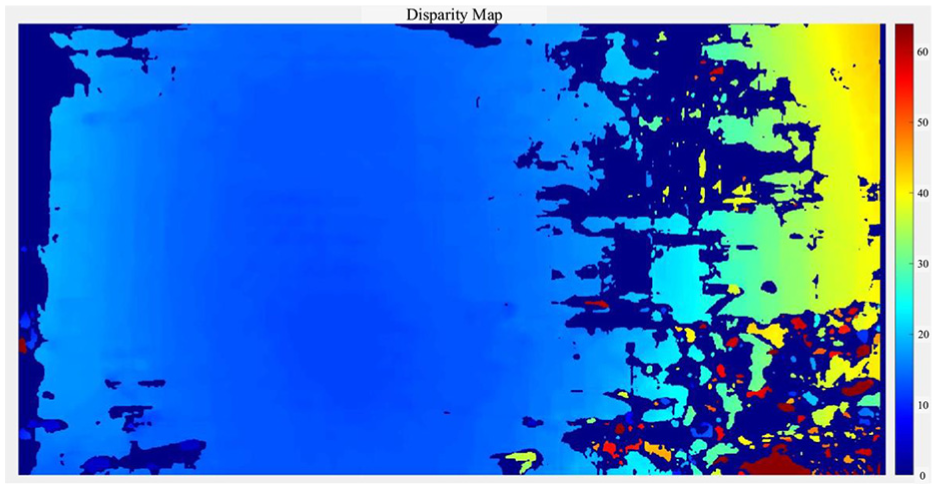
Disparity map of the video frame in the test image.
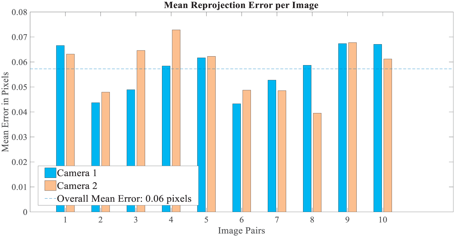
Mean re-projection error per pixel in image pairs.

Depth representation of the vehicular scenario as a point-cloud object.
After depth estimation, we determined the distance of each vehicle using the camera of the following vehicle. We had calculated the 3D-world coordinates of each detected vehicle and computed their corresponding distances using equation (10). Figure 17 shows the results of the distance calculation. The information from the vehicles is decoded from the distance values using CNN. In the time-lapse video, we found a nearest vehicle at 10.2-m distance from the following vehicle, so our system will focus on this vehicle for recognition the LED array patterns. Moreover, distance information is crucial for avoiding accidents or other critical conditions.

Measurement of distance using stereo camera–based depth estimation.
Figure 18 illustrates an example of how a CNN-based system can easily distinguish the desired light signal from ambient or others noise sources. We have determined detection and recognition performance by measuring the average precision and miss rate of our CNN algorithm. In the first step, we used the previous detection results by running the detector on the test image sets to evaluate detector performance and then executed the detection and recognition algorithm on a new scenario. To avoid long evaluation times, the results were loaded from disk and the doTraining MATLAB function was set to execute the algorithm locally. Table 2 shows the performance parameters used for the execution of the CNN-based detection algorithm, showing that weak learners in the trained classifier decrease in the final stage.

CNN-based LED signal classification under ambient noise lights.
Performance parameters for CNN-based object detection.

CNN: convolution neural network.
We had trained 300 vehicle samples for the CNN system of which 60% of the data was used for training to find the precise detection and miss rates. Figure 19 compares the detection and miss rates of our proposed CNN-based detection and recognition algorithm. The precision/recall curve highlights how precise the detector is at varying levels of recall. The average precision provides a single number that incorporates the ability of the detector to make correct classifications (precision) and the ability of the detector to find all the relevant objects (recall). Ideally, the precision would be 1 at all the recall levels. In this example, the average precision is 0.6 and the average miss rate is 0.4. The use of additional layers in the network can help to improve the average precision, but might require additional training data and longer training times. Here, we tested our approach using a single image, which showed promising results. To fully evaluate the detector, testing it on a larger set of images is recommended.
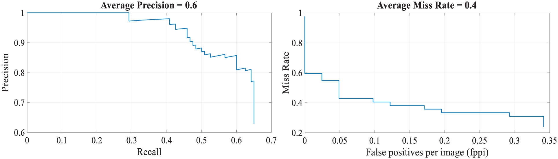
Performance of the object detector: (a) average precision and (b) average miss rate.
Meanwhile, bit error rate (BER) is the number of bit errors in the number of received bits over the communication channel due to noise, interference, distortion, or bit-synchronization errors. Therefore, minimizing BER is the key to maintaining good communication between multiple vehicles. We used the S2-PSK modulation scheme to obtain the BER versus SNR for the optical channel (considering AWGN in the channel). The simulated result for the optical channel indicates good performance when compared to the theoretical value (see Figure 20). In other words, system performance may decline as the number of vehicles is increased.
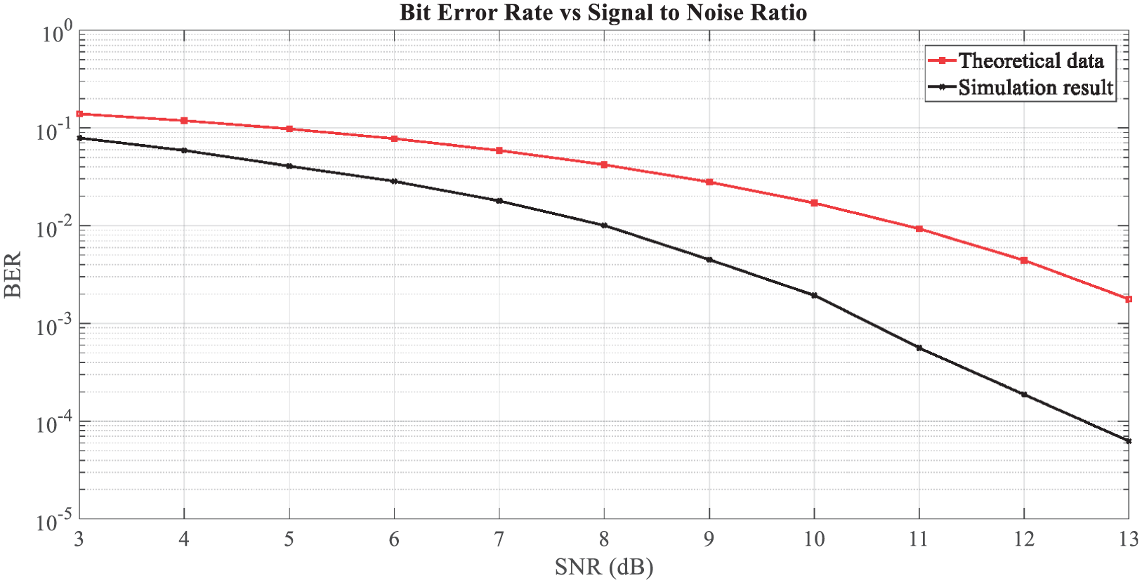
SNR versus BER.
Conclusion
This article has presented a novel intelligent IoV system based on OCC and CNN, comprising LED lights as transmitters and cameras as receivers mainly focusing on automotive vehicular applications. The purpose of this article is to provide safer, longer range, and precise detection of vehicles or other transmitters. First, we introduced the IoV system with a comparison to conventional vehicular networks (i.e. VANET). Then, we discussed our vehicular OCC system with a detailed description of the OCC transmitter, receiver, and channel model. Before moving to the simulation results, we explained our proposed scheme in detail.
We detected LED lights by discarding other light sources (e.g. the sky, digital displays, and advertising boards) using differential images and thresholding methodology. We used real-time video to obtain the simulation results. The results demonstrate the efficiency of the algorithm to differentiate signal LEDs from other light sources. We then applied the stereo camera-based distance-measurement algorithm to find the distance between the forward and following vehicle, helping the following vehicle to decode information from the forward vehicle. To verify the stability of our system, we calculated the mean re-projection errors during the camera calibration process using several image pairs. After obtaining the distance value from the stereo-vision process, we applied CNN to detect and recognize the LED array pattern form the desired targets or RoIs. The results using CNN show that our algorithm can recognize the LED array pattern precisely, even under signal blockage and bad weather conditions.
Footnotes
Handling Editor: An Liu
Declaration of conflicting interests
The author(s) declared no potential conflicts of interest with respect to the research, authorship, and/or publication of this article.
Funding
The author(s) disclosed receipt of the following financial support for the research, authorship, and/or publication of this article: This research was supported by the MSIT (Ministry of Science and ICT), Korea, under the ITRC (Information Technology Research Center) support program (IITP-2017-2016-0-00311) supervised by the IITP (Institute for Information & Communications Technology Promotion).