
Abstract
Gain calibration for X-ray imaging systems with a movable flat panel detector and an intrinsic crosshair is a challenge due to the geometry-dependent heel effect and crosshair artifact. This study aims to develop a gain correction method for such systems by implementing the Multi-Acquisition Gain Image Correction technique. Flood field images containing crosshair and heel effect were acquired in 4 different flat panel detector positions at fixed exposure parameters. The crosshair region was automatically detected using common image processing algorithms and removed by a simple interpolation procedure, resulting in a crosshair-removed image. A large kernel-based correction was then used to remove the heel effect. Mask filters corresponding to each crosshair region were applied to the resultant heel effect-removed images to invalidate the pixels of the original crosshair region. Finally, a seamless gain map was composed with corresponding valid pixels from the processed images either by the sequential replacement or by the selective averaging techniques developed in this study. Quantitative evaluation was performed based on normalized noise power spectrum and detective quantum efficiency improvement factor for the flood field images corrected by the Multi-Acquisition Gain Image Correction-based gain maps. For comparison purposes, a single crosshair-removed gain map was also tested. As a result, it was demonstrated that the Multi-Acquisition Gain Image Correction technique achieved better image quality than the crosshair-removed technique, showing lower normalized noise power spectrum values over most of spatial frequencies. The improvement was more obvious at the priori-crosshair region of the gain map. The mean detective quantum efficiency improvement factor was 1.09 ± 0.06, 2.46 ± 0.32, and 3.34 ± 0.36 in the priori-crosshair region and 2.35 ± 0.31, 2.33 ± 0.31, and 3.09 ± 0.34 in the normal region, for crosshair-removed, Multi-Acquisition Gain Image Correction-sequential replacement, and Multi-Acquisition Gain Image Correction-selective averaging techniques, respectively. Therefore, this study indicates that the introduced Multi-Acquisition Gain Image Correction technique is an appropriate method for gain calibration of an imaging system associated with a moving flat panel detector and an intrinsic crosshair.
Introduction
In digital radiography, a gain calibration procedure is essential to correct for the nonuniform response of individual pixels of a flat panel detector (FPD) to X-ray exposure. 1,2 A general gain calibration involves acquiring a flood field image and generating a gain map. This procedure generally assumes that spatially uniform intensities cover all eligible detector cells.
However, an X-ray exposure with a perfectly uniform intensity is not generally achievable in practice. Possible sources of field nonuniformity could be anode heel effect and an intrinsic obstacle between the X-ray source and imaging panel. The anode heel effect (heel effect, hereafter) is a well-known property of an X-ray tube. 3 This effect produces a gradual nonuniformity in a radiographic image; the direction of the pattern is determined by the geometry of the rotating anode in the X-ray tube. 4 Several correction methods for heel effect have been proposed based either on hardware approaches 5,6 or on computational methods. 4,7 Intrinsic radio-opaque obstacles can also cause field nonuniformity by blocking some portion of the flood field image intensities. A good example of those obstacles is an antiscatter grid. Previous studies have been reported to eliminate those artifacts from the antiscatter grid by applying image filters 8 or frequency domain processing. 9
In conventional X-ray imaging systems employing fixed source-panel geometries, the above-mentioned sources of field nonuniformity can be corrected (in the case of heel effect) or ignored (in the case of obstacle) as long as the positions of those affected pixels are consistent during acquisitions of gain-map and test images. However, one can consider special purpose imaging systems where the source and panel can move independently by translation and rotation, and equipped with an optional intrinsic crosshair, as seen in Figure 1.
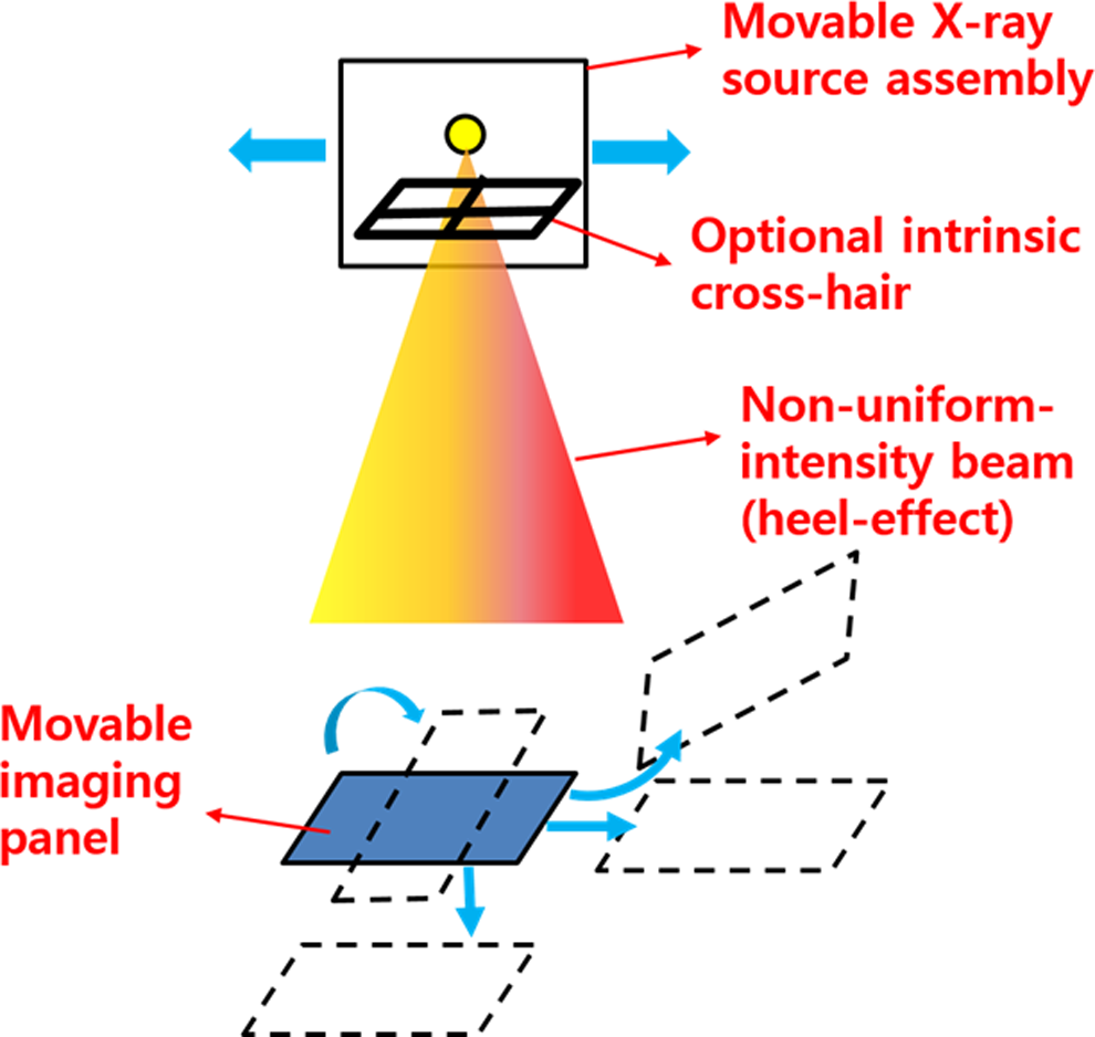
An illustration of a special imaging system associated with a movable X-ray source, imaging panel, and intrinsic crosshair.
In this system, the positions of the pixels affected by either heel effect or the intrinsic crosshair vary according to the acquisition geometry. Therefore, gain calibration for this system is challenging. We are not aware of any study that addresses gain calibration for a system associated with a moving panel (or X-ray source) and an intrinsic crosshair.
For several years, our institution has used such an FPD-based X-ray imaging system for patient localization during proton therapy treatments. Unlike ordinary X-ray imaging systems, ours has 2 unique characteristics, that is, (1) an FPD attached to the treatment couch that translates and rotates with respect to a fixed X-ray source and (2) an intrinsic crosshair fixed to the X-ray source assembly for the sake of convenient patient localization. Therefore, gain calibration for our system has been a challenge due to the crosshair and heel effect. Figure 2 demonstrates how a naive gain map obtained with the intrinsic crosshair and the geometry-dependent heel effect leads to unexpected artifacts after gain correction, especially when the acquisition geometry is different between calibration and testing.

An illustration of crosshair artifacts. A, Flood field image acquired in initial position; (B) test image acquired in different position; (C) a naive gain corrected image shows artifacts caused by an intrinsic crosshair and composite heel effect; and (D) a corrected image with a method proposed in this study (MAGIC-SA) is also presented for comparison purposes. MAGIC-SA indicates Multi-Acquisition Gain Image Correction-selective averaging.
To correct heel effect in our system, the above-mentioned correction methods are considered inappropriate, since the heel effect cannot be properly characterized in the presence of the crosshair. Moreover, regarding the crosshair artifact, the previous elimination methods for grid artifacts were not applicable due to the relatively large thickness of our crosshair.
The following 2 simple approaches were initially evaluated for our system: (1) removing the crosshair region from an acquired gain map by interpolating with surrounding pixel values and (2) generating a composite gain image from valid (non-crosshair) pixels at multiple imaging geometries. However, simple interpolation was found to still cause residual crosshair artifacts, resulting from inaccurate gain information in these regions. Moreover, the second approach was not feasible either, as variation in the heel effect for each geometry caused artifacts.
Therefore, we developed a new technique to compose a seamless gain map for an imaging system associated with the moving FPD and intrinsic crosshair. Our developed method, entitled “Multi-Acquisition Gain Image Correction (MAGIC),” involves acquiring multiple flood field images, removing the crosshair, correcting heel effect, and composition into a seamless gain map. Quantitative analysis was performed to establish the effectiveness of the proposed method.
Materials and Methods
Dedicated Imaging System for a Fixed-Beam Proton Facility
As seen in Figure 3, our proton treatment facility with a fixed beamline employs an in-house 5 degree-of-freedom (DOF) couch to allow for various treatment angles. To localize patients accurately, an orthogonal kilovoltage X-ray imaging system (horizontal and overhead) consisting of an X-ray generator (Toshiba America Medical Systems, Tustin, California), X-ray tubes (Varian Medical Systems, Palo Alto, California), and FPDs (PaxScan 4030e, Varian Medical Systems) is used. The X-ray exposure configuration was fixed at 70 kVp, 5 mA, and 50 milliseconds for all image acquisitions in this study. The output image resolution and pixel depth are 3200-by-2304 pixel 2 and 14 bit, respectively. An intrinsic crosshair geometrically aligned to the treatment beam is fixed inside the X-ray source assembly. In the overhead system, the FPD is attached to the couch and moves as a 2 DOF system (rotation and translation) with respect to a fixed X-ray source, which was the main motivation of this study.

The geometry of our dedicated imaging system for patient localization in proton therapy. An intrinsic crosshair is equipped inside the X-ray source assembly and a flat panel detector is movable according to a 2 DOF system with respect to the X-ray source.
Overview of the MAGIC Technique
The MAGIC technique begins with the acquisitions of raw flood field images (Iraw) in different panel positions. To characterize the heel effect for each image, the crosshair is detected and temporarily removed by a simple interpolation method resulting in crosshair-removed images (ICR). Next, a large kernel-based correction was used to obtain heel effect-removed images (IHR). Mask filters are further applied to invalidate the crosshair-related regions in IHR images and only valid pixel regions are prepared for gain-map composition. Two different approaches were used for final composition of gain map: (1) sequential replacement (SR) technique and (2) selective averaging (SA) technique. Either composition technique can generate a final gain map (Igain), which is used for gain correction of clinical images. A schematic illustration of the proposed MAGIC technique is shown in Figure 4. Details of the developed technique are given in the following sections.

A schematic illustration of the developed multi-acquisition gain image correction (MAGIC) technique. DOF indicates degree-of-freedom; MAGIC, Multi-Acquisition Gain Image Correction.
Removal of Crosshair in a Single Image
Figure 5 demonstrates the crosshair removal procedure. First, the input image is prepared by averaging corresponding pixels from 3 images acquired in the same geometry and exposure settings to reduce random noise. Second, median, Gaussian, and 1-directional (horizontal or vertical) derivative filters were sequentially used to identify the position of the crosshair lines. Third, a crosshair region was defined by giving a sufficiently large margin to the detected crosshair lines to account for the neighboring region of slightly lower intensity. Finally, the pixels within the crosshair region were replaced by the linearly interpolated pixel values based on valid neighborhood pixels (eg, mean values of 5 pixels close to the region border). The replacement procedures were performed for both lines of the crosshair.
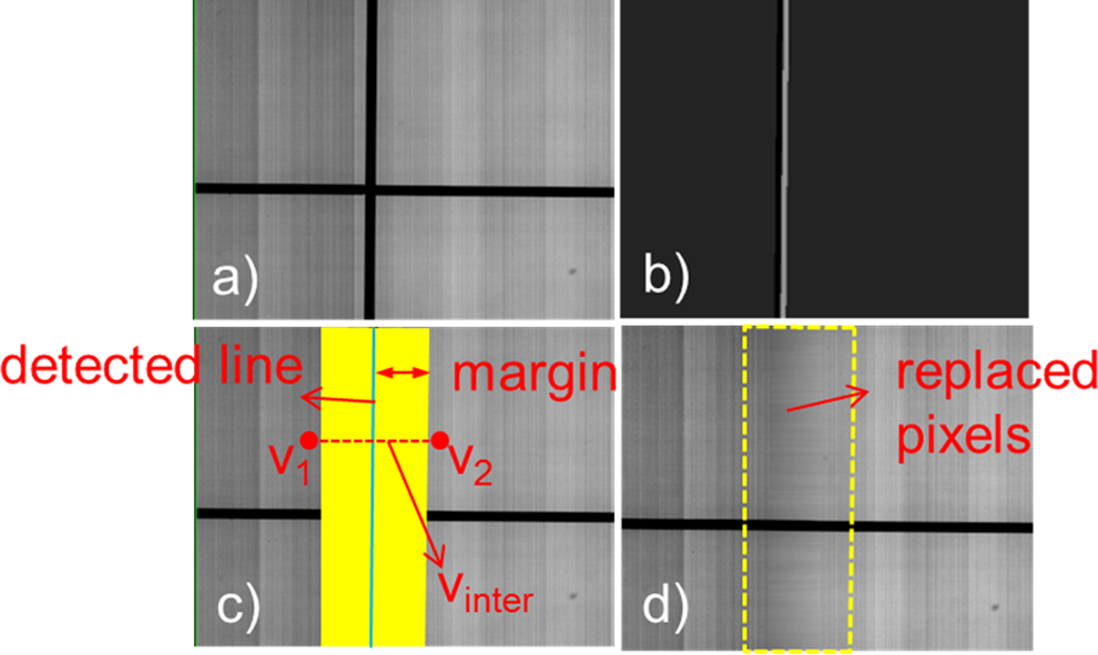
An image processing procedure to remove crosshair lines from a single image. A, An averaged flood field image with a crosshair; (B) derivative filtered image (horizontal direction); (C) pixel value interpolation (Vinter) based on surrounding pixel values (V1, V2) on the same horizontal array; and (D) intermediate image after horizontal-direction processing.
The crosshair removed image (denoted as ICR, hereafter) was utilized for 2 purposes in this study, namely, (1) an alternative gain map to be compared with the gain map from MAGIC (denoted as “single ICR image-based correction” in the Result section) and (2) an input data to generate a heel effect correction map for multiple image-based gain-map composition.
Heel Effect Correction
As mentioned earlier, it is crucial to correct the heel effect in each flood field image prior to the composition process. Otherwise, patterned artifacts may appear in the resulting gain map. Since the heel-effect causes low-frequency shading artifacts, a large kernel-based correction map was used to filter out these artifacts, similar to what was done in Schnell et al’s study. 10
We assume that an IHR can be obtained by subtracting the heel effect pixel components (Iheel) from the prepared ICR as follows:

where i and j are the coordinates of each pixel.
To obtain Iheel, the ICR image was partitioned into a m-by-n matrix where “m” and “n” values are much lower than the image full resolution, and a coarse image (Icoarse) was built by averaging the pixel values in each subsection. If the Icoarse cannot cover the whole original image region due to the round off, 1 or 2 extended sections with the same intensity values as the edge sections can be added to Icoarse to avoid fitting errors around the edge regions. In this study, a kernel with a dimension of 300-by-200 was used yielding the coarse matrix size of 12-by-13 (ie, m = 12 and n = 13). Cubic interpolation was then used to build Iheel with full resolution as follows:

where f[I] is a 2-dimensional cubic interpolant, i and j are the pixel coordinates in full resolution,
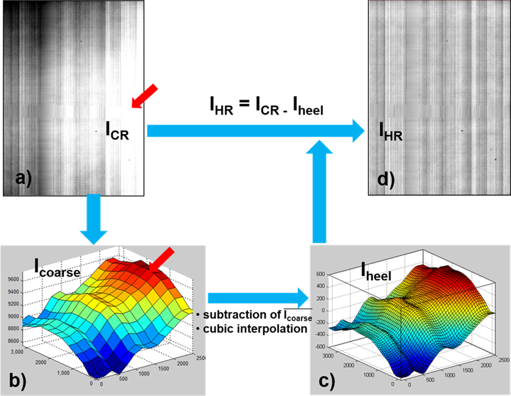
A demonstration of the heel effect removal procedure. This figure explains how to correct the heel effect after a single flood field image underwent the crosshair removal procedure. A, A crosshair-removed image (ICR); (B) a coarse image (
In Equation 2, the subtraction of
By repeating the above-described process, 4 IHR images with different crosshair positions were prepared for the gain map composition. All images were then normalized to have the same mean pixel value. An MATLAB code (The MathWorks, Inc, Natick, Massachusetts) was written to implement the heel-effect correction.
Sequential Replacement Technique
The motivation of this method was to preserve as much gain information from a single flood field as possible. Although the prepared IHR images appear to be free from the crosshair patterns, the predefined crosshair region (detected crosshair plus margin) have potentially inaccurate gain information in those interpolated region.
In this method, most parts of the gain map except the crosshair region were filled by looking up the first image among 4 IHR images. The crosshair region was then sequentially filled by referring to the corresponding regions of the other images as follows:

where

A demonstration of sequential replacement (SR) technique. To compose a seamless gain map (Igain), missing gain values in the crosshair-related regions of the primary heel effect-removed image (IHR) are filled sequentially from subsequent IHR images at the corresponding valid pixel positions.
Selective Averaging Technique
The second approach for gain-map composition that we investigated was to selectively average corresponding pixel values from IHR images after excluding outlier values. Outlier pixels were defined as those outside the range of “mean value ± 1 standard deviation.” In this study, we only prepared 4 IHR images for a gain-map composition to minimize work load. Therefore, the possible number of valid pixels to average ranged from 1 to 4 depending on the varying crosshair positions of each image. If the number is 1 or 2, a total mean value was used instead of the selective average. The composed gain map is defined as follows:

where
Quantitative Evaluation
The effectiveness of the MAGIC technique was evaluated by investigating the image quality of the gain and offset-corrected images. Gain and offset correction was carried out according to the general formula:

where
As a metric for image quality improvement, a detective quantum efficiency improvement factor (DQEIF) was calculated as presented by Schnell et al. 10 Instead of using standard procedures to directly calculate DQE, DQEIF allows for an easier calculation by comparing normalized noise power spectrums (NNPS) between uncorrected and corrected images as follows:
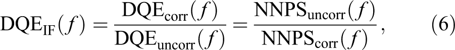
where f is the spatial frequency (mm−1) of the image.
To calculate the NNPS, an ImageJ plugin (“qa-distribution”) 11 implemented in Rogge et al. 12 was used. In total, 3 flood field images with different crosshair positions were evaluated and, for each image, 2 regions of interest (ROIs) with area of 512 × 512 pixel2 were investigated.
Results
Figure 8 illustrates a qualitative comparison of phantom images corrected by the different gain maps from the single ICR image-based correction (CR), the SR technique, and the SA technique. An uncorrected image is also presented for comparison. All 3 gain-corrected images showed improved image quality, by removing panel segment patterns from the phantom images. However, in the image corrected by the CR technique, some residual artifacts were seen inside the priori crosshair region of the gain map (denoted as Rcross hereafter). As pointed out in the Introduction section, this residual crosshair artifact is mainly due to the inaccurate gain information stemming from simple interpolation. In contrast, both of the proposed MAGIC techniques could successfully remove residual artifacts in the Rcross. When comparing the 2 composition techniques, the SA technique was found to be slightly superior to SR regarding qualitative image quality within Rcross.

The effect of different gain-map composition methods on the image quality of a phantom. The results are from (A) uncorrected image; (B) single ICR image-based correction technique; (C) sequential replacement technique; and (D) selective averaging technique. Residual crosshair pattern artifacts can be seen in the single-image–based technique (arrow).
For quantitative analysis, NNPS was computed for each strategy. To obtain more specific data on residual crosshair artifact, 1 ROI was placed on an Rcross, while the other was placed on a normal region (ROIcross and ROInormal). Figure 9 shows the normalized noise power spectra calculated for 1 test image.

Comparison of normalized noise power spectra (horizontal direction) for a flood field image corrected with different gain maps. A, Result from region of interest (ROI) on a priori crosshair region (Rcross) and (B) result from ROI on a normal region. It is shown that CR technique has limited benefit in Rcross, while sequential replacement (SR) and selective averaging (SA) techniques provided improved results over both ROIs. Note that the results of crosshair removed (CR) and SR are equivalent in ROInormal.
As expected, the CR technique was found to provide inferior image quality compared to the SR and SA techniques in the Rcross, while it was more equivalent to the SR technique in the normal region. It was also demonstrated that both the SR and the SA techniques produced consistent improvements regardless of ROI positions.
Figure 10 displays the DQEIF averaged over both directions (horizontal and vertical) with all 3 test images. Demonstrating agreement with the above-mentioned results, the CR technique showed limitations in Rcross and the SA technique was found to be the most promising. The mean DQEIF over the range of frequencies from 0.5 to 3.5 mm−1 was 1.09 ± 0.06, 2.46 ± 0.32, and 3.34 ± 0.36 in ROIcross and 2.35 ± 0.31, 2.33 ± 0.31, and 3.09 ± 0.34 in ROInormal, for CR, SR, and SA techniques, respectively.

Comparison of detective quantum efficiency (DQE) improvement factor for 3 gain-map composition techniques. A, Result from the region of interest (ROI) on a priori crosshair region (Rcross) and (B) result from the ROI on a normal region. The crosshair removed (CR) technique showed limited detective quantum efficiency improvement factor (DQEIF) in Rcross and the selective averaging (SA) technique was found to be the most promising. Note that the results of CR and SR are equivalent in ROInormal.
Discussion and Conclusion
In most X-ray imaging systems, large-scale background nonuniformities resulting from the heel effect can be easily corrected only using human visual perception. 5,7 However, for gain image composition, a software-based heel effect correction was essential. Without it, pixels from different image geometries would contain inconsistent intensity due to the heel effect, resulting in artifacts in the gain map. It should be noted that the heel effect is corrected only for the gain-map composition and not for clinical images, which implies that intrinsic heel effect remains in clinical images even after the gain and offset correction. Regarding moving geometry, Yu and Wang 13 recently introduced a novel method to correct the heel effect for gain calibration in an SID-variant environment. Compared to their work, gain calibration for our system has different challenges, including 2D DOF of panel movement and the existence of the intrinsic obstacle. To the best of our knowledge, this study is the first to address the combination of heel effect and an intrinsic obstacle in a moving FPD geometry.
To obtain an obstacle-free flood field image, a temporary removal of the crosshair assembly would have been possible. However, we preferred not to use this approach for routine gain calibration, to avoid the tedious calibration procedure needed to maintain localization accuracy with respect to the treatment beam. By using a software-based crosshair removal method, we make the procedure faster and also eliminate the small risk of systematic error in localization caused by recalibration errors.
In this study, the SA technique yielded better results than the SR technique in both qualitative and quantitative assessments. This can be explained with 2 reasons: (1) the averaging process in the SA technique reduces random noise and (2) in the Rcross, small normalization uncertainties in heel removal might be visible on the border between pixel groups from different IHR. The SA technique efficiently reduces those effects by excluding outlier pixels. Another advantage of the SA technique over the SR technique is that it removes minor artifacts presumably caused by nonuniformities within the plastic cover of the X-ray source assembly. These nonuniformities demonstrate the same behavior as the intrinsic crosshair, even though they are not explicitly identified. As seen in Figure 11, it was found that the SA technique could remove such artifacts efficiently.

Defects or nonuniformities inside the X-ray source assembly act as intrinsic obstacles, causing artifacts in corrected images. A, Region of high attenuation is found in a raw flood field image; (B) a white artifact region can be seen in a phantom image acquired at a different geometry corrected by the sequential replacement (SR) technique; and (C) the artifact can be removed by the selective averaging (SA) gain-correction technique.
In conclusion, it was demonstrated that the introduced MAGIC technique could accomplish the gain calibration for an imaging system associated with a moving FPD and an intrinsic crosshair system. The technique showed advantages over a conventional single image-based technique by successfully reducing residual crosshair artifacts, thus showing higher image quality with respect to DQE. We expect that this technique would be beneficial for the facilities where either moving FPDs or intrinsic obstacles are involved.
Footnotes
Acknowledgments
The authors appreciate the effort of Justin Phillips for English proofreading.
Declaration of Conflicting Interests
The author(s) declared the following potential conflicts of interest with respect to the research, authorship, and/or publication of this article. All authors certify that his manuscript has not been published in whole or in part nor is it being considered for publication elsewhere. The authors have no conflicts of interest to declare.
Funding
The author(s) disclosed receipt of the following financial support for the research, authorship, and/or publication of this article: This work was supported in part by NIH P01-CA021239-29A1 and NIH/MGH Federal Share C06CA059267.