
Abstract
Keywords
Introduction
Breast cancer ranks among the most prevalent cancers globally. 1 Surgery, chemotherapy, and radiation therapy constitute the three primary treatment modalities for breast cancer. 2 In radiation therapy, employing a bolus over the mastectomy scar or chest wall can increase the surface dose of the skin and reduce the risk of local recurrence. 3 Although the benefits of this practice are debated, the current consensus is that in cases where the risk of skin recurrence is high, using a bolus to improve the skin dose should be considered to reduce the recurrence probability.4,5 In clinical practice, there are two methods for adding skin compensators: the first method involves personalized compensators based on 3D printing technology for patients. The advantage of these customized 3D printed compensators is that they fit closely with the skin, with very small gaps between them, ensuring that the planned dose is relatively close to the actual dose. 6 However, the downside is the high technical requirements and cost involved. As a result, many hospitals may not have the capacity to provide individual compensators for each patient. The second method involves using common standardized compensators, usually in the form of bolus, and achieving conformity with the irradiation field as much as possible through trimming.
There are two methods for placing standardized bolus. The first method involves adding the bolus during CT scanning. The advantage of this approach is that the treatment team can adjust, trim, or shape the bolus to enhance its fit with the skin and reduce air gaps. This adjustment helps minimize uncertainty in treatment planning by considering air gaps and correcting Hounsfield unit assignments used for dose calculation. However, not all clinicians may accurately determine the boundaries of the area requiring an increased skin dose, especially without relevant CT imaging, which could lead to insufficient doses in high-risk areas for skin recurrence. Moreover, modifying the bolus fit during CT simulation positioning can be time-consuming, potentially reducing staff efficiency. In the second method, a bolus is not initially placed during the CT scan; instead, a virtual bolus is incorporated during treatment planning based on clinical requirements to elevate the skin dose on the chest wall. An actual bolus is then added during treatment within the parameters of the planned virtual bolus. This method excels in accurately delineating high-risk areas for skin recurrence, ensuring adequate coverage with the bolus. However, compared to directly placing a bolus during CT scans, there is a trade-off when using a virtual bolus in the planning process followed by placing a bolus during clinical treatment.
In the Eclipse Treatment Planning System (Varian Medical Systems, Palo Alto, CA, USA), the bolus inserted in the plan is closely adhered to the skin. However, in clinical practice, due to the presence of differences in air gaps between the skin and bolus caused by chest wall folds, surgical incisions, and the potential flexibility of the bolus, these differential air gaps cannot be accurately accounted for in precise dose calculations. There have been studies investigating the clinical and dosimetric effects of these air gaps. Butson et al and Chung et al found that under static 6 MV photon irradiation, having a 1-cm air gap beneath the bolus can reduce the surface dose of the phantom by up to 10%. Additionally, the reduction in dose is most significant for angles closest to the vertical direction and the smallest field sizes.7,8 Khan et al's research also indicates that under orthogonal static 6 MV photon irradiation with field sizes smaller than 10 × 10 cm2, air gaps larger than 1 cm can lead to a surface dose reduction of over 10%. For larger radiation fields, the decrease in dose is minimal. 9 In previous phantom testing studies, comparisons were made between doses calculated using various treatment planning systems (TPS) and actual measured doses (typically using film, ion chambers, or MOSFET detectors).10,11,12 Due to factors such as the susceptibility of film measurements to environmental influences, the insensitivity of ion chambers to steep dose gradients, and uncertainties related to the size and positional accuracy of MOSFET detectors, actual measurement of surface dose poses significant challenges. In a study by Boman et al, it was reported that the analytic anisotropic algorithm (AAA) was found to underestimate surface dose compared to Monte Carlo calculations. Additionally, if there are air gaps under the bolus, VMAT techniques significantly reduce surface dose compared to field-in-field treatments. 13 All of the above studies share a common characteristic: in the same scenarios, the distance from the bolus to the surface remains fixed, and the volume of air gap between the bolus and the skin is relatively large. However, these conditions do not align with actual treatment scenarios. In the case of radiation therapy for breast cancer, the anatomical structure of the breast often undergoes significant changes along with patient respiratory motion. Regardless of the compensators or techniques used, air gaps between the compensator and the skin persist.
To the best of our knowledge, no previously published studies have analyzed the impact of varying, irregular small-volume air gaps on the local skin dose in breast radiotherapy with tangential IMRT. Additionally, there is a lack of research examining the effect of the average angle of the lateral beam (AALB) on the skin dose near air gaps. This study aims to determine the impact of variations in air gap volume due to small irregular depth errors on the local skin mean dose (Dmean), normal tissue complication probability (NTCP), and tumor control probability (TCP) for postoperative radiotherapy in breast cancer patients. Through a retrospective multivariate analysis of a large patient cohort, we considered the skin's Dmean as a function of air gap volume and AALB. Based on this analysis, a predictive model for skin Dmean was established to quantify the impact of skin dose caused by errors in air gap depth.
Methods and Materials
Patients and Target Delineation
In this study, we retrospectively selected 55 breast cancer patients who required irradiation of the chest wall and supraclavicular lymph node region, with the majority clinically staged at I–III. Among them, 14 patients had involvement of the internal mammary nodes. Our inclusion criteria were based on the presence of significant depression in the chest wall or noticeable folds in the breast, with bolus solely added to the chest wall. The patients were anonymized, and approval was obtained from the Institutional Review Board of the First Affiliated Hospital of Gannan Medical University, with the Ethics review number LLSC-2024-115. We utilized a breast holder device from Klarity (China) for patient positioning, followed by free-breathing CT scanning. The treatment planning CT images were acquired using the GE Discovery RT590 scanner with a thickness of 5 mm and imported into Eclipse TPS (version 15.5). We contoured the clinical target volume (CTV) following the guidelines of RTOG, including the chest wall and supraclavicular and/or axillary lymph nodes. 14 By applying a 5-mm uniform expansion to the CTV, we generated the planning target volume (PTV) and cropped it to the skin surface on the chest wall. 15 Lastly, we employed AccuContour software (Manteia Technology, China) to automatically segment organs at risk (OARs), such as the heart, spinal cord, lungs, and contralateral breast, which were then reviewed by experienced oncologists.
The air gap errors were all simulated on the original CT image using Eclipse TPS, with the simulation positioned at the skin depression or inframammary fold. The process for constructing the original air gap errors is as follows: within the post-processing module, the select VOI range box of the Enhancement function was used to determine the range of air gap errors to be placed, and the smoothing level was set to 20, which was then applied to body0 to generate the target structure body1. Subtracting body0 from body1 resulted in the generation of the air gap error Air0. Air0 was expanded outward by 5 mm in front and left or right (depending on whether it was the left or right side of the treatment area), generating Air0 + 5 mm. body0 was uniformly expanded by 2 mm to produce body + 2 mm, and the intersection area between body + 2 mm and Air0 + 5 mm represented the air gap error, Air2, with a depth of 2 mm. The generation process for Air3 and Air5 was essentially the same as that for Air2, with the only difference being that body0 needed to be uniformly expanded by 3 mm and 5 mm to create the corresponding structures body + 3 mm and body + 5 mm. We adopt the definition by Xinfeng et al that the skin is a structure 5 mm thick on the anterior surface of the breast. 16 The region to the left or right of Air5 (depending on whether it belongs to the left or right breast treatment) is defined as the local skin for which we need to recalculate the dose. The detailed process for generating the air gap errors and the local skin is illustrated in Figure 1.

The detailed process for generating the air gap errors with a depth of 2 mm and the local skin.
In this study, we followed the STROBE guidelines outlined in the Equator Network to ensure transparency and quality in our research. 17
Treatment Planning
The planning of all original plans was performed using Eclipse version 15.5 (VMS, California, USA). The optimization conditions included using the Millennium 120 MLC, a dose rate of 600 MU/min for 6 MV photons, while employing the AXB dose calculation algorithm, with a calculation grid size of 1.25 × 1.25 mm2. The prescription dose was 50 Gy delivered in 25 fractions. All plans utilized tangential beam, with 7 to 9 beams inserted based on individual patient anatomy. The collimator angle and JAW size were adjusted to better shield the lungs and heart, and to focus on the target volume for each beam. The original plans were normalized to achieve a mean dose of 100% of the target volume, and a bolus was added to each plan to enhance skin dose. During the optimization process, normal tissue was further protected by utilizing the normal tissue objective function and organ-specific penalties. We will integrate Air2, Air3, and Air5 into the body structure and adjust the bolus placement to cover these air gaps. Subsequently, all plans will undergo recalibration.
For AALB, as shown in Figure 2, the α1, α2… and αn represent the angle interval of original tangential field setup by the planner. The value of AALB, denoted by θ, is determined using the following equation (1):


The α1, α2, … and αn represent the original tangential field angle interval. The value of AALB, denoted by θ, is determined using the following equation: θ = (α1 + α2 +…+ αn)/n; the value of n is one less than the number of original fields.
The value of n is one less than the number of original fields.
Evaluation Dosimetric, NTCP, and TCP of Local Skin
Dmean was analyzed based on the AALB and the volume of air gap, and subsequently utilized for calculating NTCP and TCP for the local skin. Intrapatient correlations were accounted for using generalized estimating equations (GEEs).18,19 The impact of Air gap volume on V105 at the AALB was characterized through multivariate linear regression when AALB was at a specific value, as shown in equation (2).
20

In this research, a Poisson linear-quadratic (PLQ) model was constructed to determine the TCP of the skin. Källman et al thoroughly examined the PLQ model in a prior study,
21
along with the dose–response characteristics utilizing the logistic function as follows:


For the skin toxicity, a Lyman Kutcher–Burman (LKB) NTCP model was established to calculate the toxicity risk to the local skin. Details of the LKB model analysis have been described previously,
25
and the parameterization of the dose–response characteristics using the logistic function is as follows:


Statistics
Estimates for the parameters were computed along with p-values and confidence intervals. The identity link of the normally distributed data was assessed utilizing the Kolmogorov-type supremum test, which was employed to simulate the cumulative sum of the residuals as an indicator of goodness-of-fit. 27 Statistical significance was assessed at p < .05. All statistical analyses were performed using SPSS 20 (SPSS Inc., Chicago, IL, USA).
Results
Patient and Treatment Characteristics
In the study involving 55 patients, the average and standard deviation of Air2 volume were 4.5 ± 2.1 cc, Air3 volume was 8.3 ± 3.0 cc, and Air5 volume was 13.4 ± 4.61 cc. The mean and standard deviation of local skin volume were 15.2 ± 5.6 cc. The AALB exhibited a wide range, ranging from 2.5° to 55.0°, with an average and standard deviation of 15.91 ± 17.07°. Additionally, 165 plans were simulated and recalculated in addition to the initial 55 plans. Patient characteristics and planned radiation fields can be found in Table 1.
Characteristics of the 55 Patients Enrolled in This Study.

Abbreviation: SD = standard deviation.
Quality Comparison of Dmean, TCP and NTCP
The average change in local skin dose was characterized by simulating air gaps of 2 mm, 3 mm, and 5 mm at breast depressions or folds. In Figure 3, Dmean values as a function of AALB were plotted for different depths of air gap errors. A quantitative evaluation of the average, standard deviation, and range of DVH, TCP, and NTCP indicators for local skin is described in Table 2. When simulating an air gap depth error of 2 mm, the average Dmean in plan2 increased by 0.46 Gy compared to the initial plan (planO), which was statistically significant (p < .001). Only two cases in plan2 had a lower Dmean than in planO. When the air gap was increased to 3 mm, the average Dmean of plan3 was 0.51 Gy higher than that of planO, with statistical significance (p < .001). In plan3, there were three cases where the Dmean was lower than in planO. When the air gaps were simulated as 5 mm, the average Dmean of plan5 was significantly greater than that of planO (p < .001) by 0.59 Gy, and there were four cases where the Dmean of plan5 was less than that of planO. As the air gap depth error increased, the local skin Dmean also increased. The Dmean of plan5 was 0.08 Gy greater than that of Plan3 and 0.13 Gy greater than that of Plan2; the Dmean of Plan3 was 0.05 Gy greater than that of Plan2. This indicates that the Dmean values for larger air gap depth errors were significantly greater than those for smaller air gap depth errors (p < .001). The results of TCP showed a similar trend to those of Dmean. Compared to planO, the average TCP values for plan2, plan3, and plan5 increased by 0.07, 0.14, and 0.18 percentage points, respectively, with significant differences between each other. As the depth error gradient increased, the gradient of TCP increase showed a decreasing trend. For NTCP, as the depth of air gaps error increases, the NTCP values also rose gradually. When compared to planO, the NTCP values for plan2, plan3, and plan5 increased by 0.09, 0.09, and 0.11 percentage points, respectively, showing significant differences between each plan.
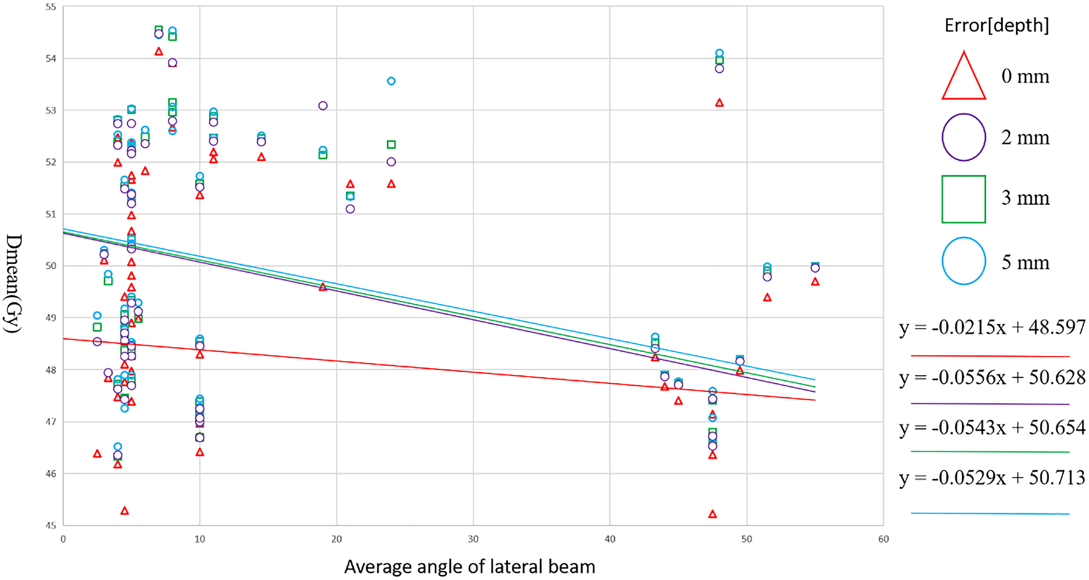
Dmean value is plotted as a function of AALB and stratified by rotational error. Abbreviations: Dmean = mean dose of skin; AALB = average angle of the lateral beam.
Quantitative Evaluation of DVHs Metrics for 55 Test Patients among Plan O, Plan 2, Plan 3, and Plan 5.

Abbreviations: TCP = tumor control probability; NTCP = normal tissue complication probability. SD = standard deviation.
i = Plan O vs Plan 2; ii = Plan O vs Plan 3; iii = Plan O vs Plan 5; iv = Plan 2 vs Plan 3; v = Plan 2 vs Plan 5; vi = Plan 3 vs Plan 5.
Dmean Multivariate GEE Linear Regression Analysis
The linear regression of the multivariable GEE equation indicates that the volume of air gaps and the AALB are strong predictors of Dmean. The model's predictions for Dmean under various air gap depth errors are statistically significant. For detailed parameter estimates, confidence intervals, and p-values, please see Table 3. The Kolmogorov-type optimal test procedure suggests that the three linear GEE models fit well for depths of 2 mm, 3 mm, and 5 mm error (p > .05). The relationship between Dmean and AALB is illustrated in Figure 4, stratified by different volume ranges. When the air gap depth error is 2 mm, Dmean increases by 8.6 times as much per unit increase in volume (cc) as it decreases per unit increase in AALB (°). With a 3-mm air gap depth error, Dmean increases by 4.9 times as much per unit increase in volume (cc) as it decreases per unit increase in AALB (°). In the case of a 5-mm air gap depth error, Dmean increases by 3.3 times as much per unit increase in volume (cc) as it decreases per unit increase in AALB (°). It is evident that as the depth error increases, the influence of air gap volume on Dmean gradually decreases.
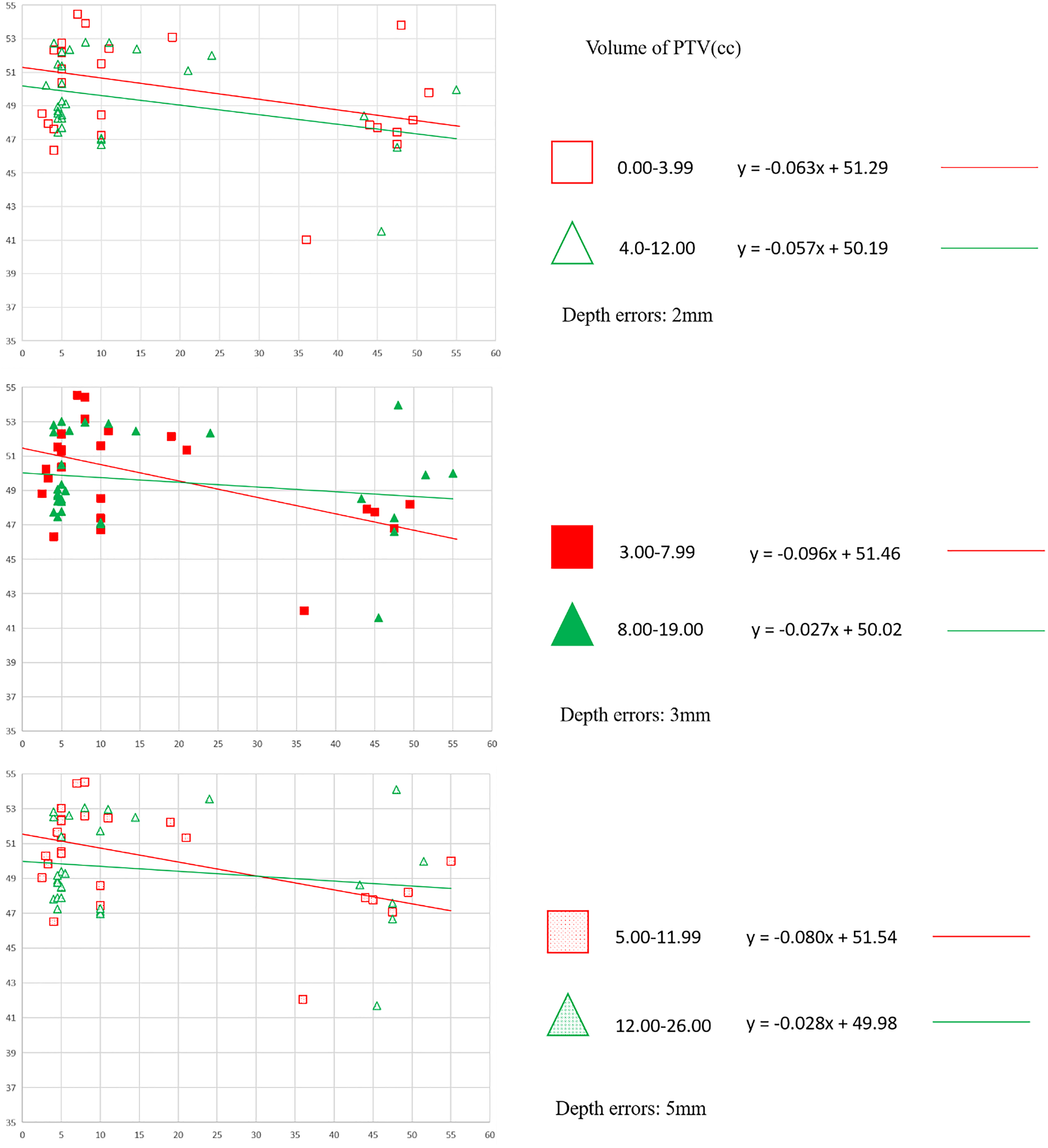
Dmean value is plotted as a function of AALB and stratified by depths of 2 mm, 3 mm and 5 mm. Abbreviations: Dmean = mean dose of skin; AALB = average angle of the lateral beam.
GEE Multivariate Linear Regression Model (Equation (1)) for Predicting Skin0 Dmean as a Percentage of the Prescription Dose (Depth Errors).

Abbreviations: CI = confidence interval; D95 = dose to 95% of planning target volume; GEE = generalized estimating equations. The model is parameterized at depth errors of 2 mm, 3 mm, and 5 mm. Dmean GEE linear regression model as show in equation (1).
Figure 5 illustrates the impact of depth errors of 2 mm, 3 mm, and 5 mm on skin dose measurements in the presence of a significant depression in the chest wall. Across the three error levels of 2 mm, 3 mm, and 5 mm, the average local skin dose increased significantly compared to the original planO, by 0.06 Gy, 0.14 Gy, and 0.27 Gy, respectively.
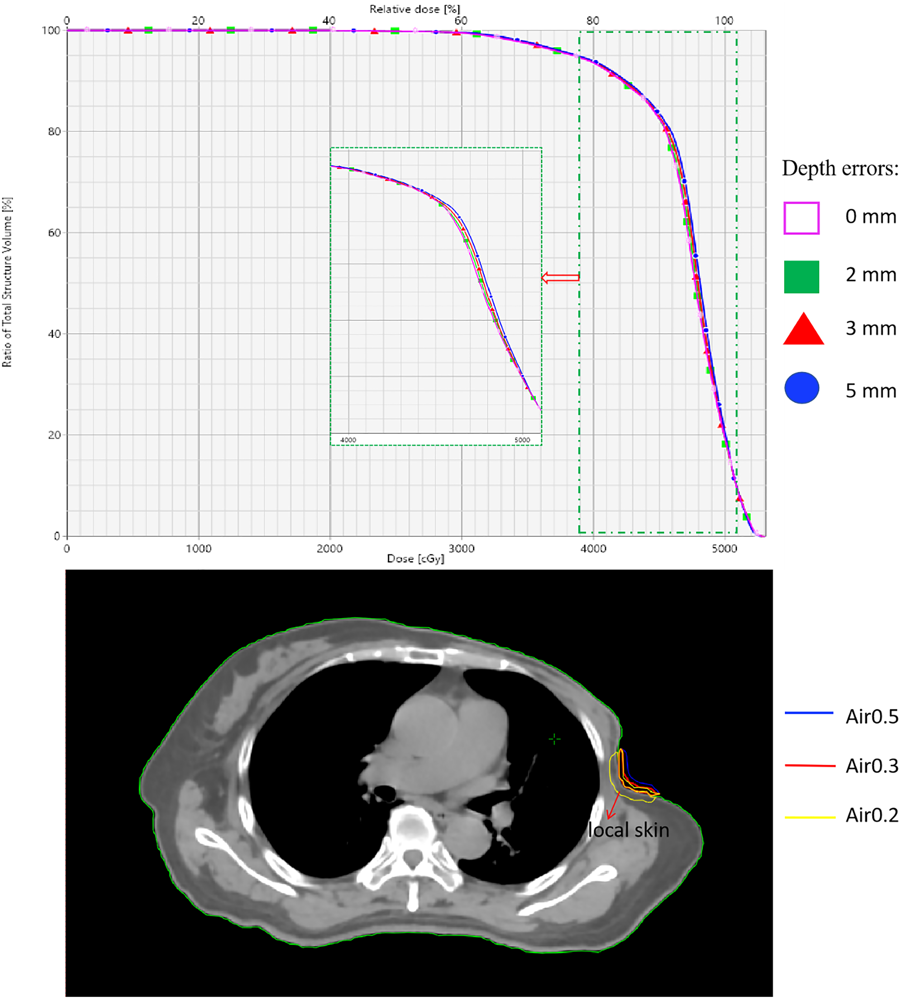
The effect of 2 mm, 3 mm, and 5 mm depth errors on local skin. A patient with significant depression in the chest wall.
Discussion
The research findings indicate that at depths of 2 mm, 3 mm, and 5 mm, the presence of air gaps caused by depth errors results in an increase in the Dmean of the local skin. Simultaneously, the increase in TCP is slightly greater than NTCP. A generalized linear model was utilized to quantify the impact of the volume of air gaps and the AALB on the local skin's Dmean. It was discovered that the volume of air gaps and the AALB are significant predictors of the average dose of the local skin. Under the same depth error of air gaps, the impact of dose is greater with a unit volume of air gaps. As the volume of air gaps formed by deeper cavities increases, the increase in the dose of the local skin gradually decreases. These findings contribute to further evaluating the TCP and NTCP of the local skin for each patient. Specific air gap and field parameters for individual patients can be easily obtained from TPS as the system provides tools for outlining and measuring volumes. This allows for assessing the impact of TCP and NTCP on the local skin during each fraction of the treatment process. Additionally, the model for the Dmean of skin is robust and can be widely applied to estimate the dose impact on the skin caused by errors in air gap volumes across various treatment machines, by incorporating more model data.
In this study, we simulated different scenarios of air gap errors at varying depths in depressed areas of the skin or under the inframammary fold, creating corresponding air gap scenarios labeled as Air2, Air3, and Air5. The study did not cover cases where there are large errors in air gap volumes, as these have been addressed in previous studies. The selection of air gap depth error levels was based on prior research on air gap errors. Khan et al evaluated the impact of air gaps between bolus and skin within the range of 0 to 5.0 cm on dose effects, indicating that air gaps smaller than 10 × 10 cm2 significantly affect surface doses when the field size is less than 10 cm2 and there are significant changes in the surface contour or small coverage areas at the beam edge. 9 Dilson et al studied surface doses when air gap depths varied uniformly between 0 and 15 mm using 3D-CRT technology, showing varying degrees of dose increase on the surface. 28 Butson et al demonstrated that vertical beam incidence on the phantom surface results in a slight decrease in skin dose, with 90% of the maximum dose still passing through a 10-mm air gap between the bolus and skin surface. 7 Benoit et al have proven that air gaps disrupt the electron equilibrium of the radiation beam, potentially affected by factors such as photon energy, air gaps, field size, and bolus thickness, thereby re-establishing dose accumulation in near-surface regions. 29 Therefore, the focus of this study is on quantitatively analyze the effect of air gap volumes and AALB on the dose of local skin in breast cancer under irregular conditions with small depth of air gaps using IMRT technology.
This study examines the interaction between air gap volume errors and the AALB to describe the dosimetric effect of air gap depth errors on the local skin. However, there are many other complex factors that may significantly impact local skin dosimetry. In clinical practice, errors in air gap depth, patient positioning displacement, and rotational errors may occur. 30 While displacements and rotational errors are typically corrected during fractionated treatments, variations in the original air gap depth due to intra-fractional positioning errors can also occur. The lack of robust measurements for depth errors in high-risk skin areas, such as surgical incisions, presents a significant clinical challenge that requires further evaluation. Since the depths of air gap may vary dynamically during treatment, it is necessary to develop a robust quantitative analysis method to accurately assess skin surface doses and further determine corresponding skin responses. Additionally, the institution lacks dosimeters (eg, Thermoluminescent Dosimeters (TLDs), diodes, or Metal Oxide Semiconductor Field Effect Transistor Dosimeters (MOSFETs)) for in vivo dosimetry to verify appropriate skin doses for patients; thus, there may be differences between calculated and delivered doses to some extent.
Conclusions
In conclusion, not placing bolus during CT scanning and subsequently adding bolus based on the virtual bolus range designed by TPS during treatment constitutes an effective method to increase skin dose and improve TCP. However, when there are small air gaps between the skin and bolus, not only does TCP increase, but the NTCP of the local skin also increases. The multivariable linear GEE regression model may effectively explain the impact of air gap volume and AALB on the local skin.
Footnotes
Authors Contributions
Chunbo Tang did data curation, methodology, project administration, writing draft. Jun Yuan did data curation, methodology, project administration. Hailiang Guo did data curation and formal analysis. Zhongyang Dai did data curation, and investigation. Haiyan Xi did investigation, project administration. Biaoshui Liu: Formal analysis, investigation. Ji He did conceptualization, formal analysis, writing—review, and editing. Shanzhou Niu did conceptualization, formal analysis, and editing. Chunbo Tang and Jun Yuan have contributed equally to this work. Ji He and Shanzhou Niu are co-corresponding authors.
Declaration of Conflicting Interests
The authors declared no potential conflicts of interest with respect to the research, authorship, and/or publication of this article.
Ethics Statement
The use of patient data was approved by the institutional review board at the First Affiliated Hospital of Gannan Medical University with Ethics review number of LLSC-2024-115.
Funding
The authors disclosed receipt of the following financial support for the research, authorship, and/or publication of this article: This work was supported in part by the National Natural Science Foundation of China (62261002), Science and Technology Program of Jiangxi Province (20192BCB23019, 20202BBE53024),Jiangxi Double Thousand Plan (jxsq2019201061).
Generated Statement
No animal studies are presented in this manuscript.
Inclusion of Identifiable Human Data
Generated Statement: No potentially identifiable human images or data is presented in this study