
Abstract
In this paper, a new type of core-spun compound aramid yarn has been applied in the construction of UD fabric to investigate if the ballistic performance of the whole fabric could be positively influenced. Three types of fabrics (Fa, Fb and Fc) herein have been developed. Fa is the traditional type of UD fabric with two layers laying at the angle of 0°/90°. Fb is made by adding new CSC aramid yarns inside of Fa at the angle of 0°/90°. Fc is further developed from Fb via changing yarn-ply directions as 45°/-45°, to analyze if the yarn-ply directions would influence on the ballistic performance of new UD fabric. The result is quite positive, as it shows that Fb and Fc have apparent energy absorption capability than Fa, and Fc is the best. This indicates that the introduction of core-spun compound aramid yarns could indeed improve the ballistic performance of UD fabric, and the yarn-ply direction of 45°/-45° is better than that of 0°/90° to absorb more energy. This research has been investigated with the assistance of both the ballistic test and the FEA model. Energy absorption and penetration resistance mechanism are the two major aspects to analyze to reflect the ballistic performance of these fabrics.
Keywords
Highlights
• A new UD laminate using core-spun compound (CSC) aramid yarns has been invented and created. • This new UD laminate has been proved to provide better ballistic performance than the current UD laminate using filament aramid yarns only. • The yarn-ply direction of 45°/-45° is proved to be better than that of 0°/90° to absorb more energy. • Ballistic test has been carried out to investigate experimentally. • FEA models have been established to analyze theoretically.
Introduction
High-performance fabrics composed of aramid yarns or UHMWPE yarns, are considered as important materials in the ballistic application due to their high strength, high modulus, and other excellent properties.1–13 Their mechanisms to absorb and dissipate energy during the ballistic impact have been widely researched. It has been found that the stress transfer at points of interlacements, the yarn pull-out, the yarn fracture, and the inter-yarn friction are the main factors.14–20 Among them, the inter-yarn friction is not the first factor, but plays as a fundamental role as it influences other factors directly and widely. As a matter of fact, many researchers have engaged in the investigation of the relationship between the inter-yarn friction and the ballistic performance of the fabric.21–23
The inter-yarn friction plays an important role in the research of ballistic performance. Briscoe and Motamedi found that the aramid woven fabric with higher inter-yarn friction could absorb and dissipate impact energy more effectively.24,25 Chu etc. discovered that no matter for aramid woven fabric or for UHMWPE woven fabric, higher inter-yarn friction could lead to more areas involved in ballistic energy absorption from both experimental and numerical methods.26,27 Sun etc. used the yarn-gripping method to increase the inter-yarn friction to enhance the capability of ballistic energy absorption and dissipation. 28 Cao etc. concluded that the ballistic performance of Kevlar® fabric could be improved by doping shear thickening fluid (STF), which could strengthen the inter-yarn friction coefficient and increase the bearing area of the fabric. 29 Park etc. also revealed that the impregnation of shear thickening fluid (STF) could be used to increase the ballistic energy absorption by increasing the inter-yarn friction.30–32
However, most studies of inter-yarn friction are focused on the ballistic fabric with woven type, not UD type (unidirectional laminate fabric), because of the rigid formation of the latter. This is difficult to make treatment directly on the exiting UD laminate due to the yarns inside already paralleled and bonded by resin. Nevertheless, as a major type of ballistic materials, UD laminate has the apparent advantage in quickly spreading away the strain waves and therefore owns high energy absorption capability; its ballistic performance is highly worthable to research.33–36 However, though the ballistic performance for UD laminate has been widely studied,37–42 most research is based on the exiting UD laminate. This is because it is difficult to develop new yarns and apply new rarely inside the laminate to make new UD laminate. While as the basic component of UD laminate, yarn is the fundamental factor determining the ballistic performance of UD laminate directly.
This paper is focusing on developing a type of UD laminate using a kind of new yarn – core-spun compound (CSC) aramid yarn, which is supposed to provide better ballistic performance than the traditional UD laminate without CSC yarns. This is because the CSC aramid yarn could increase the inter-yarn friction inside the structure, and therefore to improve the ballistic performance positively. Additionally, the structure with the yarn-ply direction of 45°/−45° and that of 0°/90° are also investigated and compared for structural optimization. This research would be analysed by both the ballistic test and the FEA model.
Laminates creation
The CSC aramid yarn was made of filament aramid yarn spun with staple aramid fiber. Its structure sketch is shown in Figure 1. The specification of this CSC aramid yarn is listed in Table 1. The main characteristic of CSC aramid yarn is that it may provide better inter-yarn friction in the laminate due to the usage of coarse staple aramid fiber winding on the filament aramid yarn, compared to the original single yarn composed of smooth filament aramid fiber only. The structure for CSC aramid yarn and laminates. Specification of CSC aramid yarn.

Three types of UD laminate fabrics were created in this paper, marked as Fa, Fb and Fc, as shown in Figure 1. Fa was the most common type of UD laminate with two layers laying at the angle of 0°/90°. Kevlar®29 was used to make Fa. The same filament aramid yarn (Kevlar®29) winded with the staple aramid fiber to become CSC aramid yarn, was further added inside of Fa at the angle of 0°/90° to make new UD laminate, known as Fb. The purpose of using the same Kevlar®29 to make CSC aramid yarn was to make parameters as close as possible, to increase the comparability of ballistic performance between Fa and Fb. Fb was further developed to become Fc with changing yarn-ply directions as 45°/-45°, to investigate if the yarn-ply directions would influence on the ballistic performance of new UD laminate.
Due to the technical difficulty and high R&D cost of manufacturing UD laminate with CSC aramid yarns in the factory, new experimental apparatus to help lay yarns in different directions to make new UD laminate according to the plan of this research, is of necessity and has been developed. As show in Figure 2, this apparatus was designed and inspired by Eight-Diagram Tactics from Chinese culture. A groove was made on each edge for inserting needles to lay yarns from different directions. After yarns laid out, epoxy resin was used to bind yarns together to make laminates. Without developing this new apparatus, it was impossible to create new UD laminates and impossible to carry out this research effectively. Procedures of creating laminates.
Ballistic test
The samples were ballistically tested at the ballistic laboratory. The sample was cut into 12 × 12 cm2, clamped by a pair of metal clamps for ballistic test. The full-clamped sample was then located on the ballistic apparatus to test the ballistic performance, as illustrated in Figure 3(A) and 3(B). This ballistic apparatus consisted of a firing device with a 7.62 mm rifle barrel, the target holder and time detectors. Propelled by gunpowder, the rifle barrel fired the projectile, which penetrated at the full-clamped laminate fixed on the target holder. The projectile was a 9 mm Parabellum FMJ bullet with the weight 8g, which was the standard bullet clarified in the international ballistic standard - NIJ standard. The impact velocities were ranged from 220 m/s to 350 m/s. The time detectors then picked up the travelling time of the projectile before and after the target. Ballistic Test: (A) testing apparatus; (B) schematic diagram of testing apparatus; (C) samples after test.
In principle, the energy absorbed by the target fabric on penetration assessing the ballistic performance of fabric is measured by the decrease in projectile kinetic energy, which is determined from the projectile impact velocity and the exit velocity. The loss in kinetic energy carried by the projectile after going through the laminate can be calculated using equation (1):

The exit velocity
The samples after test are shown in Figure 3(C). It could be noticed that for all these three types of laminates, the area around the shooting point is smoother on the strike face than on the back face, and yarn failure phenomena such as yarn pull-out and yarn fracture all could be observed on the back face apparently. This is because when the projectile hits the laminate, high temperature comes out with the kinetic energy to melt yarns and resin at the same time. The melted resin in the laminate around the hit point may still stick yarns and avoid coarse appearance. When the yarn is continually pulled by the projectile and away from the laminate, very little resin is still on the damaged yarn and the yarn failure phenomena become more and more obvious. Additionally, the yarn failure phenomena are quite apparent in the direction of laying yarns on the back face as shown in Figure 3(C), due to the reason that the gap between yarns where the resin is filled is easier for the projectile to penetrate.
Results of ballistic tests.
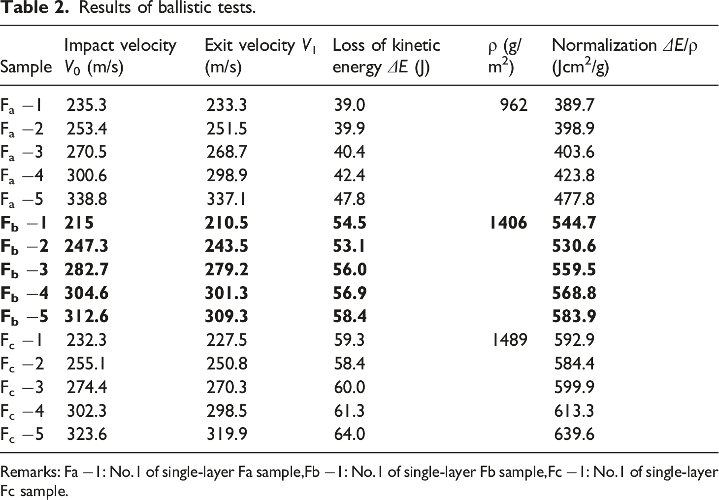
Remarks: Fa −1: No.1 of single-layer Fa sample,Fb −1: No.1 of single-layer Fb sample,Fc −1: No.1 of single-layer Fc sample.

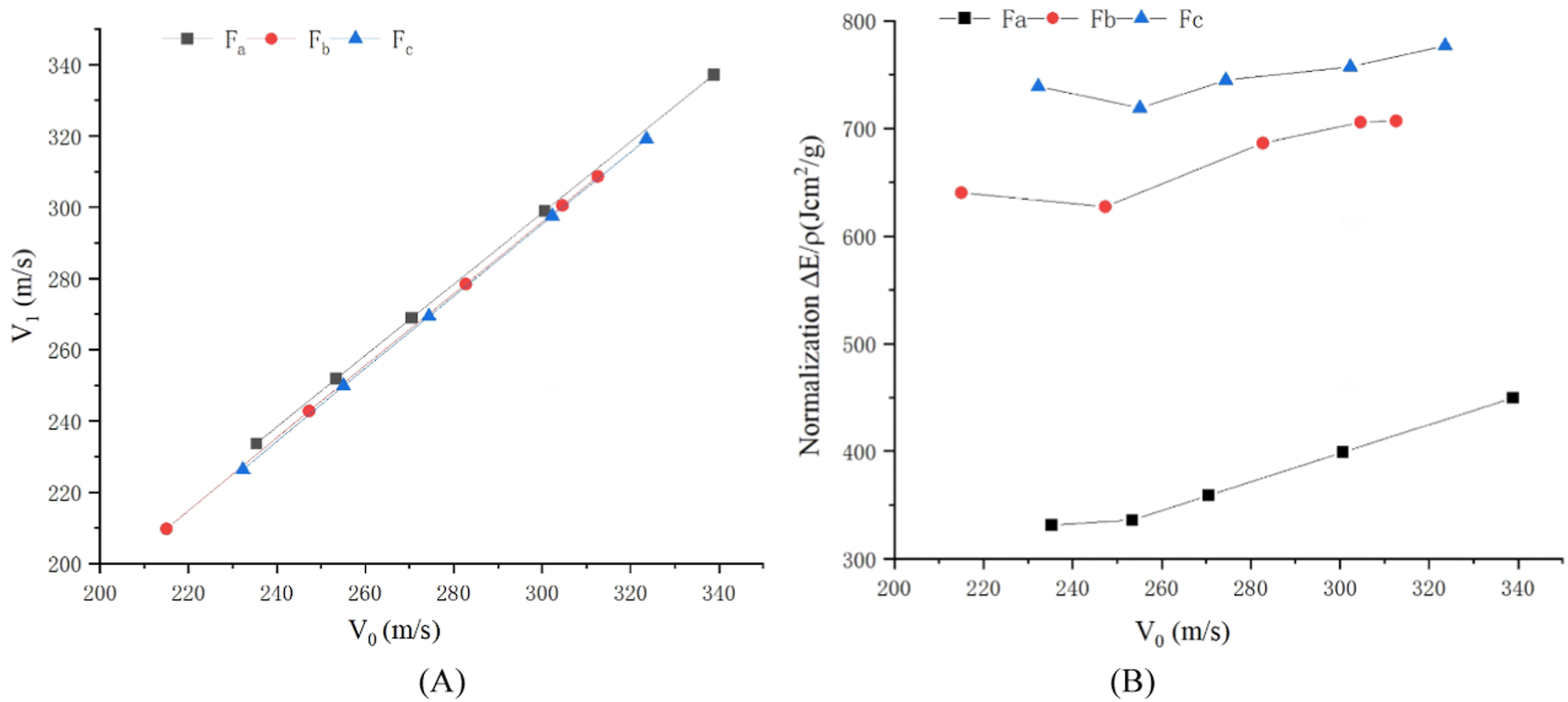
Trends of samples Fa, Fb and Fc after ballistic test: (A) V0 versus V1; (B) V0 versus energy after normalization.
It can be noticed that no matter for Fa, Fb and Fc, the trend of V1 is going up stably when V0 increases, and there is no fluctuation during these processes, as show in Figure 4(A). This may indicate that for all types of laminates including Fa, Fb and Fc, a similar relationship between V1 and V0 can be expected; the variation of velocity is stable before and after impacting, and no special impact velocity or exit velocity is discovered to make a big difference in this relationship.
Figure 4(B) shows the situation of energy absorbed with the increase of V0 for the types of laminates Fa, Fb and Fc. The first important discovery can be found that the overall trends of both Fb and Fc are higher than that of Fa apparently, which demonstrates that the introduction of using CSC aramid yarn can enhance the ballistic performance effectively. This is because CSC aramid yarns are composed of filament fibers wrapped up by staple fibers, which can increase the friction among the yarns inside the laminates to help improve the energy absorption. Secondly, Fc shows better ballistic performance than Fb, which indicates that the angle variations of different layers can make a positive influence on improving energy absorption effectively. According to the energy absorption mechanism, when the projectile hits the laminate, the primary yarns absorb much more impact energy than the secondary yarns in the laminate, as the former stand the impact of the projectile directly and the latter stand it indirectly. The secondary yarns are indirectly influenced because they are interacting with primary yarns and the impact energy can propagate along the laminate in the forms of longitudinal wave and transverse wave. Therefore, for the multi-layer structure, if different layer lays in different angle, the yarns in the next layer supposed to be secondary yarns now become primary yarns which can help to absorb energy more evenly and effectively. This theory speculation is now verified and also workable for the construction of new UD laminate in this paper. The third characteristic is that no matter for Fa, Fb and Fc, the overall trend of energy absorption capability is increasing with the increasement of impact velocity. This maybe because the filament aramid yarn used in the laminate is a high-strain rate material. The high the impact velocity, the more apparent the energy absorption capability demonstrates. Fa shows this characteristic most apparently as the yarns to form Fa are filament aramid yarns only. However, the interesting point can be found that when the impact velocity is low, Fb and Fc also show high energy absorption capability. This maybe because the yarns to form Fb and Fc are CSC aramid yarns which composed of not only filament aramid fibers but also staple fibers. The staple fibers play a role in increasing friction, which show more influence on Fb and Fc when standing the low impact velocity. But this factor may be decreased due to the high-strain rate property of filament aramid fibers when the impact velocity increases as limited time for reaction while the staple fibers are broken quickly under the high impact velocity.
Finite element analysis analysis
In order to understand the ballistic performance of these three different types of laminates theoretically, the corresponding FEA models have been established to compare and analysis with the assistance of Catia, Hypermesh and Ls-Dyna software. Catia software was used to create the geometrical model, then was meshed by Hypermesh software and further processed to establish FEA model by Ls-Dyna software.
Establishment of FEA model
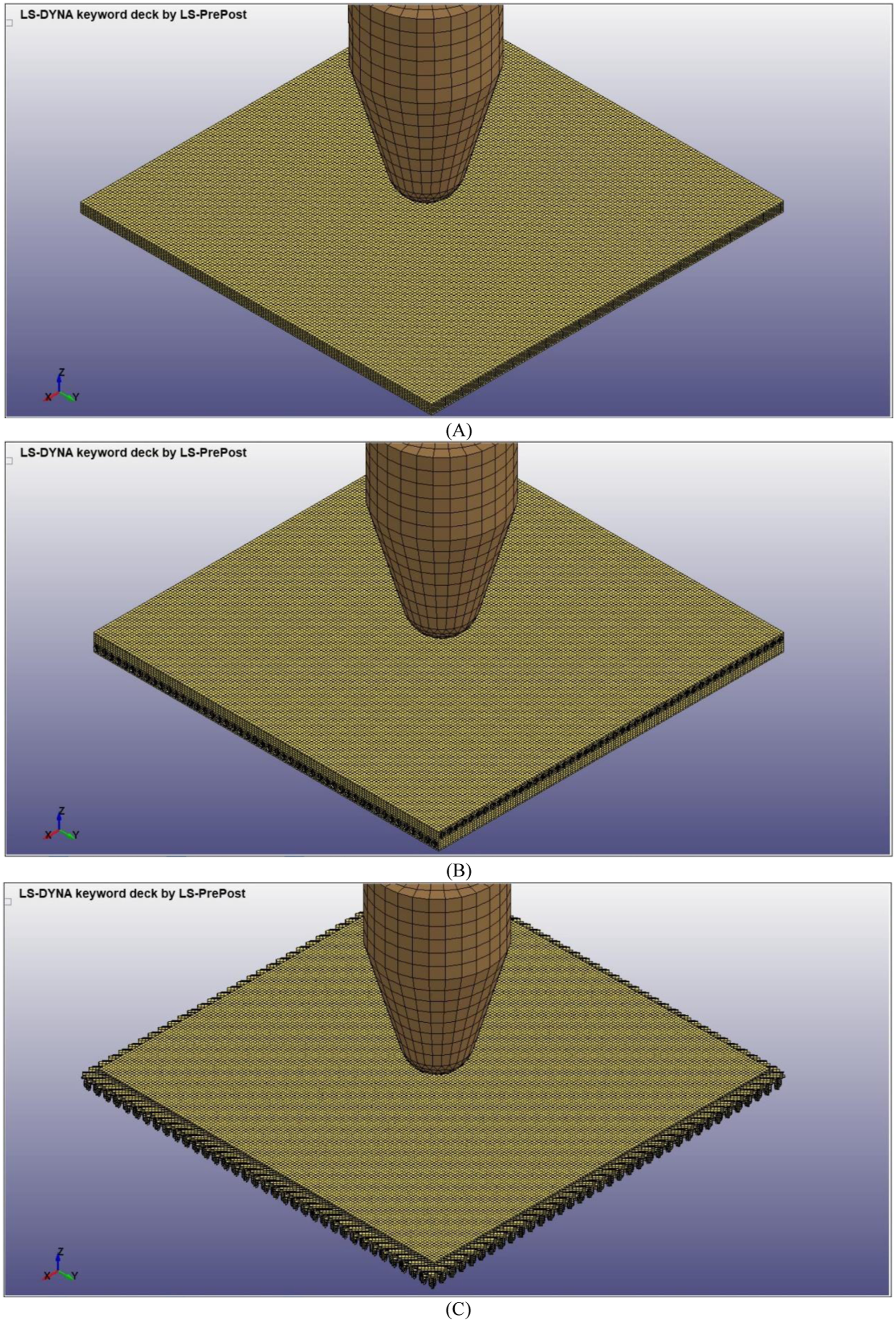
In this paper, three types of geometrical models of laminates Fa, Fb and Fc were created in Catia software. The geometrical models of laminates were constructed by assembling the models of yarns and the models of resin. The basic yarn models can be described as three types: a 3D solid object with a rectangle cross-section extracted in a straight line (marked as Model R), a 3D solid object with a rectangle cross-section extracted in a screw line (marked as Model S) and a 3D solid object with a circular cross-section extracted in a straight line (marked as Model C), as shown in Figure 5. Model R, which was used to assemble the geometrical laminate model Fa, was further connected with Model S and Model C to assemble the geometrical laminate model Fb and Fc. The parameters were based on the practical measurements (Unit: mm). The basic geometrical models of laminates Fa, Fb and Fc are shown in Figure 6. The whole geometrical models were completed by repeating the basic geometrical models in both X and Y directions. Basic geometrical models for yarns and laminates: (A) Model R; (B) Model S; (C) Model C; (D) Fa; (E) Fb; (F) Fc. FEA model with a bullet: (A) Fa; (B) Fb; (C) Fc.
The geometrical models of laminates were further meshed using Hypermesh software. There were totally 29,034 elements for Fa model, 705,024 elements for Fb model, and 753,938 elements for Fc model. The geometrical model of projectile was established based on the parameters of 9 mm Parabellum FMJ bullet, which was then meshed with 1470 hexahedron elements on the body and 1000 tetrahedron elements at the bottom.
The meshed geometrical model was further processed to complete the establishment of FEA model by setting definition of material properties, definition of section properties, application of boundary conditions and velocity to the bullet. All those information was saved as K files in Ls-Dyna software.
The definition of material properties is set up in the “Model and Part” section of LS-Dyna program. Three categories of keyword commands (element, node and part) are set here. Then in the “MAT” section, “003-PLASTIC_KINEMATIC” and “020-RIGID” are defined for fabric model and projectile model respectively. The properties for the material model are input in “Keyword Input Form”. Then a new form of “New ID” is open to fill the parameters of the real fabric and that of the bullet. Then all settings are accepted to finish the definition of material properties.
The definition of section properties is set up in the “Section” part of LS-Dyna program. “SOLID” is chosen for fabric model and projectile model. “Keyword Input Form” is open to allow input of properties for this section setting.
The application of material & section properties to the model is related to the order of “SECID” and “MID” in the “PART” section of “Keyword Manager” window. “SECID” is updated as “Solid Section” for fabric model, and “Solid Section” for projectile model. The setting of boundary conditions and velocity to the bullet, are carried out on the form of “Entity Creation” of “Model and Part” section, and on the form of “Keyword Manager” respectively. After all settings are confirmed, all information could be saved as k. file. Then then whole model will be processed to calculate finally.
The FEA models for Fa with a bullet, Fb with a bullet and Fc with a bullet are individually shown in Figure 6.
Verification of FEA model
Observation of phenomena
According to the energy absorption mechanism, when the projectile hits the fabric, longitudinal wave and transverse wave take place. The former wave travels through primary yarns which directly hit by the projectile, and secondary yarns which not directly hit by the projectile but interacting with primary yarns in the plane of the target plate. The latter wave propagates outwards from the impact zone to make deformation like a cone with an impact point at its vertex in the perpendicular direction to the fabric plane. All these phenomena could be illustrated and verified in these three types of FEA models. Other characteristics, such as yarn failure, yarn pull-out, yarn fracture after ballistic test in the experiment also can be observed and demonstrated in these FEA models, as shown in Figure 7. Illustration by FEA model: (A) Fa; (B) Fb; (C) Fc.
Data analysis
Results calculated by FEA models.

Trends of samples Fa, Fb and Fc after FEA analysis: (A) V0 versus V1; (B) V0 versus energy after normalization.
In Figure 8(A), it also shows that with the increase of V0, V1 increases correspondingly with no fluctuations. This may theoretically prove that the variations of impact velocity before and after penetration are likely to be stable without being influenced by a certain velocity. The comparisons between V0 and energy after normalization calculated by FEA models for three different laminates Fa, Fb and Fc are shown in Figure 8(B). It could be noticed that the overall trends composed by these theoretical data are very close to those composed by experimental data demonstrated in Figure 4(B). Fb and Fc also show better capability of energy absorption than Fa, and Fc is the best no matter under the low impact velocity or high impact velocity. This may verify the validity of the FEA models. The only little difference is that the excess of energy absorption that Fb or Fc surpasses Fa is more apparent in FEA models than in ballistic tests. This may because the laminate in this paper is simplified as a solid object for FEA model to illustrate the energy absorption mechanism, which may be more theoretical to demonstrate the overall trend than in the real ballistic tested condition that the real laminate is made by yarns composed of thousands of filaments (for Fa) or thousands of filaments and staple fibers together (for Fb and Fc). The non-simultaneous failure of each filament or staple fiber with complex interface friction may lead to a complicated energy absorption mechanism in the real experiment. However, the overall trend with major factors analysis maybe the key point that the paper should focus on. Compared to Fa, the superiorities of Fb and Fc are further theoretically analyzed from the aspects of energy absorption, penetration resistance and stress distribution which are mainly important to demonstrate the ballistic performance of laminates.
Theoretical discussion
Energy absorption
The details of energy absorption analysis are investigated to understand the influence of structure difference on the ballistic performance. The samples of Fa with impact velocity 300.6 m/s, Fb with impact velocity 304.6 m/s and Fc with impact velocity 302.3 m/s are chosen to compare as they have similar velocities, but Fc is still higher than Fa and Fb, and Fa is the lowest, which still reflects the overall trend, as shown in Figure 9. The comparisons among them maybe relatively convincible to reflect their different characteristics. Analysis of energy absorption: (A) comparisons of energy absorption in total; (B) the comparisons of energy diffusion modes between Fb and Fc (view at the bottom).
Figure 9(A) shows the variation of energy absorption in total for Fa, Fb and Fc during different times. The first apparent point is that no matter during which time, Fb and Fc are always higher than Fa apparently. The energy absorption in total shown in Figure 9(A) also demonstrates the same result. This may theoretically emphasize that Fb and Fc are superior to Fa in terms of ballistic performance with the usage of CSC yarns.
Secondly, for Fa, Fb and Fc, the peak values of energy absorption in total are different as shown in Figure 9(A). For Fa, the peak value appears around 7µs, and the trend goes down apparently and quickly. This peak value is quite low, almost only 1/2 or 1/3 of that for Fb and Fc. This may indicate that during the whole procedure against the projectile penetration, the capability of energy absorption for Fa is always weaker than Fb and Fc and can’t surpass them at any moment. For Fb and Fc, both go up sharply in the first period of 10µs, then Fb stays at its peak value around 14-15 Jcm 2 /g and decreases gradually after 40µs, while Fc fluctuates apparently and achieves its peak value around 17 Jcm 2 /g at 40µs. The different CSC yarns ply direction inside the structure maybe the reason to cause the difference between Fb and Fc.
Additionally, the energy absorption in total for Fc is better than that for Fb as shown in Figure 9(A), which indicates that the structure of Fc is better than that of Fb in terms of ballistic performance, but the energy absorption in certain time for Fc is not always larger than that for Fb. In the beginning to 10µs, the trend of Fb and that of Fc are similar, which indicates that when the projectile hits and almost penetrates, both types of laminates demonstrate to absorb the similar energy in the similar period. The difference of structure between Fb and Fc seems not give apparent influence in the initial stage. However, when the projectile goes further, Fb and Fc demonstrate different trends. The trend of Fb is more stable than Fc. In the second stage (around 10µs to 27µs), when the projectile starts to penetrate and goes through the laminate, Fb seems to absorb more energy than Fc; while in the next stage (after 27µs to the end), the energy absorption capability of Fc increases sharply and overpasses that of Fb. This may because they have different structures to absorb energy. The yarns to compose the structure for Fb are laid at the angle of 0°/0°/90°/90°, which is a regular ply direction for the projectile penetrating easily and stably. While for Fc, the structure is more complicated; the yarns inside are laid at the angle of 0°/45°/-45°/90°. As shown in Figure 9(B), though the same strike & back-face layers and the same resin are given to Fb and Fc, the modes of energy diffusion are apparently different, as influenced by the different yarn-ply directions, namely, the middle two layers with different ply directions (0°/90° for Fb and 45°/-45° for Fc). The style of 45°/-45° yarn-ply direction maybe more difficult for the transverse wave and the longitudinal wave to do the reciprocating motion along with the yarns and the resin. A larger ballistic resistance is easier to form in Fc than in Fb. The projectile later may need dissipate more energy to overcome this larger resistance to penetrate the laminate in the final stage and leave it completely.
Apart from that, different parts for each laminate in the energy absorption were further analyzed to explain the ballistic performance influenced by the characteristics of structures. The first eye-catching and interesting point could be noticed that if without considering CSC yarns, other parts, especially the strike-face layer and the resin demonstrate very similar trends with quite close data in all three different types of laminates, when comparing the corresponding curves among (A), (B) and (C) in Figure 10. However, the trends of energy absorption in total for Fb and Fc are apparently much higher than that for Fa. This may strongly prove that the introduction of CSC yarns can really enhance the ballistic performance of UD laminate. Another mutual discovery could be found that in all these three types of laminates, the strike-face layer and the resin engage in the ballistic mechanism from the beginning, and the back-face layer engages in it after a few µs later. This accords with the experimental procedure that the projectile touches the strike-face layer firstly, then penetrates further until it leaves the whole laminate finally. The third important discovery is that though CSC yarns are introduced to both Fb and Fc, the trends of energy absorbed by CSC yarns in Fb and Fc are different, only because CSC yarns are plied to form the middle two layers with different ply directions (0°/90° for Fb and 45°/-45° for Fc); which further directly and apparently influences the trends of energy absorption in total. This may clearly demonstrate the relationship between the characteristic of structure and the capability of energy absorption of the whole laminate. Besides, it can be noticed that the introduction of CSC yarns could positively affect the capability of energy absorption for the back-face layer, as the value of energy absorbed by the back-face layer is increased more obviously in Figure 10(A), (B) than in Figure 10(C), maintaining around 3Jcm
2
/g compared to 1Jcm
2
/g, while the variations of energy absorption for strike-face layer and the resin are not apparent. Energy absorption of different parts: (A) Fa; (B) Fb; (C) Fc.
Furthermore, the ratio of energy absorption distribution also has been considered. Internal energy and kinetic energy are the major two types of energy absorption distribution. From Figure 11, it can be noticed that Fa and Fb have the similar energy ratio between internal energy and kinetic energy, around 45% versus 55% compared to 44% versus 56%. This may indicate that even CSC yarns are introduced in Fb, because the whole structure hasn’t changed, as still formed by laying yarns at the angle of 0°/90°, the energy absorption distribution hasn’t changed too much from Fa to Fb, which seems to be more apparently influenced by variations of structures, not by variations of yarns. Besides, Fc shows quite larger internal energy than kinetic energy, around 54% versus 46%, which is largely different from Fb, though CSC yarns are also introduced in Fc. This may emphasize that the variations of structures would directly affect the energy absorption distribution, as Fc has a different structure with the middle two layers with ply directions 45°/-45°. Ratio of energy absorption distribution:(A) Fa; (B) Fb; (C) Fc.
Penetration resistance
Penetration resistance is an important property to investigate as it can reflect the ballistic performance of laminates. In Figure 12, the overall trend of velocity variation for Fa, Fb and Fc are similar, decreasing sharply in the first stage, slightly in the next stage, and finally maintaining unchanged. This complies to the real situation that the projectile meets the largest penetration resistance in the beginning as it starts to strike the whole structure, and then decreases when it penetrates further and finally leaves the laminate. However, three stages of velocity variation for Fa, Fb and Fc are different. Velocity and acceleration versus time history:(A) Fa; (B) Fb; (C) Fc.
For the first stage of sharp decrease, Fa is shorter than Fb and Fc, as it can be observed that Fa needs around 7µs while both Fb and Fc need 10µs, shown in Figure 12. This may indicate that Fb and Fc could provide better penetration resistance than Fa as the projectile needs more time to overcome and penetrate inside. This complies to the research in the energy absorption; as shown in Figure 9(A), in the first 10µs, Fb and Fc already indeed absorb more energy than Fc apparently.
For the second stage of mild decrease, it can be noticed that Fa starts at 7µs and finishes at 37µs, earlier than Fb (starting: at 10µs; finishing: at 43µs) and Fc (starting: at 10µs; finishing: at 60µs). It seems when the projectile goes further and into the laminate, the structure of Fa is easier to be penetrated and costs quite less time than Fb and Fc. This may because the structure of Fa is simpler than Fb and Fc, as Fb and Fc are further developed based on Fa with adding CSC aramid yarns at the angle of 0°/90° and at the angle of 45°/-45° respectively. The complicity of structure in Fb and Fc may consume the projectile more time against yarn fracture, yarn pull-out, resin damage, and other failure mechanisms. The more complicated structure, the more time is needed for the projectile to penetrate. It can be noticed that the second period of mild decrease for Fc is the longest as the structure for Fc is the most complicated. This complies to the research that Fc has been approved to own the largest capability of energy absorption, compared to Fa and Fb, as shown in Figures 4 and 8.
For the third stage of maintaining unchanged, this is because the projectile has penetrated the laminate completely without obstacles, the velocity keeps stable.
Typical times (5µs, 30µs and 55µs) in these three stages are chosen to observe the ballistic penetration of laminates Fa, Fb and Fc, as shown in Figure 13. In the first stage, it can be noticed that stretching is the major formation in the laminate to stand the largest initial penetration in the beginning. All the related yarns and resin are resisting this penetration in the formation of stretching, and some locations are further breaking. For example, for Fb and Fc which have more complicated multi-layers than Fa, the back-face layer is starting to stretch while the strike-face layer has finished stretching and is tending to breakage. In the second stage, the formation becomes quite varied. Cone deformation, yarn pull-out, yarn fracture and resin breakage, all phenomena could be observed when the projectile further penetrates and tires to go through Fa, Fb or Fc. In the third stage, for all laminates, the impact velocity is inclined to be stable, as the laminate has been penetrated completely and the penetration resistance tends to disappear. Performance of ballistic penetration at 5µs, 30µs and 55µs:(A) Fa; (B) Fb; (C) Fc.
The relationship between the acceleration and the time history also has been observed, as shown in Figure 12. It can be noticed that there are also three periods for Fa, Fb and Fc, namely, sharp increase, apparent fluctuation, and final stability. This applies with the similar trend of velocity variation. The largest increase of acceleration can be found in all the first period for Fa, Fb and Fc. But this value at the corresponding time is different: Fa shows around 299 m/s at 3µs, Fc shows around 297.8 m/s at 4µs, and Fb even shows two peak values around 301.5 m/s at 3µs and 7µs. This may indicate again that different structure shows different performance.
In the second period, the fluctuations for Fa, Fb and Fc are very apparent, but all are far smaller than the fluctuations in the first stage. This is because in the first stage, the projectile carries the largest energy and starts to give stress to the laminates, the yarns and the resin in the laminates tend to provide the largest penetration resistance against the projectile. In the second stage, the laminate has been penetrated; the confrontation between the projectile and the laminate becomes weak. Instead of shear format, stretch format becomes the major type of the failure mode. Yarn pull-out, yarn fracture and resin breakage can be found apparently. Besides, in the second period, it also can be noticed that different structure makes different influence on the acceleration of the projectile. For Fa, the trend is comparatively simple, an obvious bound can be found and then tend to return to zero quickly. This is because the structure of Fa is simple, traditional two-layer UD laminate structure. The projectile is easy to penetrate in a quite short time. For Fb and Fc, their structures are complicated but different, the penetration resistance provided by the yarns and the resin inside these laminates against the projectile is also demonstrated to be complicated but different. Additionally, compared to Fa and Fb, the projectile spends most time inside of Fc to get rid of the influence of penetration resistance, as it can be noticed that almost at 65µs the acceleration tends to reduce to zero, shown in Figure 12 (C). This may prove again that the superiority of the structure of Fc, which could provide the best capability against the high-velocity impact of the projectile.
Conclusions
In this paper, three different UD laminates, including two new types with the usage of CSC aramid yarns, have been created and compared to investigate their ballistic performance. The result is quite exhilarating. With the introduction of CSC aramid yarns, the energy absorption capability of the whole laminate could be highly improved. Ballistic tests and FEA models have been used to analyze the ballistic performance of these laminates from the perspective of both experimental and theoretical ways. The major contributions of this research are listed as follows.
Three types of laminates with different structures, known as Fa, Fb and Fc, have been successfully created and manufactured. Fa was the common UD laminate type. Fb was created by adding CSC aramid yarns at the angle of 0°/90° inside of Fa. Fc was further developed from Fb by changing yarn-ply directions as 45°/−45°.
These three types of laminates Fa, Fb and Fc have been ballistically tested. The experimental results show that Fb and Fc have better ballistic performance than Fa as the energy absorbed by Fb and Fc are apparently higher than Fa. This may indicate that the usage of CSC aramid yarns could indeed make positive influence on improving the capability of energy absorption in UD laminate type. Besides, Fc is better than Fb which further indicates that the structure laying at the angle of 0°/45°/-45°/90° has better advantage in energy absorption than the structure of laying at the angle of 0°/0°/90°/90°. The variations of angles could indeed affect the ballistic performance of the whole structure. However, these data now are collected when the impact velocity varies from 220 m/s to 350 m/s. The trend is unclear if the velocity is higher than 350 m/s. There is still blank space of study and needed future research.
FEA models have been established to provide the theoretical data to compare with the experimental data. The theoretical results show a good coincidence with experimental results: Fc demonstrates the best ballistic performance as it can the provide the largest energy absorption no matter at which velocity; Fb and Fa rank 2nd and 3rd respectively. FEA models also show the comparisons between V0 and Energy after normalization calculated by FEA models for different laminates Fa, Fb and Fc; the result demonstrates that with the increase of V0, V1 increases correspondingly with no fluctuations, very similar to the trend illustrated from the experimental data. This may prove that the impact velocity before and after penetration is unlike to be influenced by a certain velocity from both theoretical and experimental ways.
The details of energy absorption for these three different laminates have been further investigated by FEA models. It could be found that no matter during which time, Fb and Fc are always higher than Fa apparently. The peak value of energy absorption in total for Fa is always weaker than Fb and Fc. Besides, Fb is better than Fc in the energy absorption in total, though not in every moment, due to their structure differences. In terms of different parts of the laminate in the energy absorption, it could be clearly noticed that the introduction of CSC yarns could highly enhance the capacity of energy absorption. While for the energy absorption distribution, this is apparently and directly influenced by the variations of structures rather than the usage of CSC yarns.
The penetration resistance of these laminates also has been theoretically analyzed in detail. For the overall trend of velocity variation, Fa, Fb and Fc show the same trends: decreasing sharply in the beginning, fluctuating slightly later, and keeping stable finally. These similar three periods could be found when the relationship between the acceleration and the time history is investigated. The theoretical analysis also shows that Fb and Fc have better penetration resistance than Fa, and Fc is the best due to the superiority of its structure, which highly complies to the discovery in the research of energy absorption.
Footnotes
Acknowledgments
Authors sincerely appreciate the support from the Top-notch Academic Programs Project of Jiangsu Higher Education Institutions (TAPP), and the Priority Academic Program Development of Jiangsu Higher Education Institutions (PAPD).
Declaration of conflicting interests
The author(s) declared no potential conflicts of interest with respect to the research, authorship, and/or publication of this article.
Funding
The author(s) disclosed receipt of the following financial support for the research, authorship, and/or publication of this article: This work was supported by the 4th Leading Innovative Talents CultivationProject of Changzhou City; CQ20210106, School Start-up Fund Project of Changzhou University; ZMF21020365 and research project of MenBo High-tech Jiangsu Co., Ltd; 2022K3071.