
Abstract
This article presents an investigation regarding the ballistic performance of hybrid panels formed by combining woven and unidirectional (UD) para-aramid fabrics. For this purpose, hybrid panels are formed by combining woven and UD para-aramid fabrics with different ply ratios. The hybrid panels formed in this way are subjected to ballistic tests according to National Institute of Justice (NIJ) standard. The results show that hybrid panels present 4.48% less trauma depth as compared to 100% woven fabric panels and 3% less trauma diameter as compared to 100% UD fabric panels. Furthermore, 13.9% less energy is transmitted to the back side of hybrid panels as compared to 100% UD fabric panels. The energy absorbed per unit weight in hybrid panels is 8.48% more as compared to 100% woven fabrics. Additionally, in wet conditions, less trauma depth of hybrid panels is observed as compared to both 100% woven and 100% K-Flex UD fabric panels. No significant difference is realized in trauma diameter between hybrid panels and 100% woven fabric panels in wet conditions. However, 3.25% less trauma diameter is noticed in hybrid panels as compared to 100% UD fabric panels.
Introduction
Ballistic protective materials, especially personal protective textiles, are expected to have low weight, flexibility and comfort properties in addition to ballistic performance. For this reason, researchers have concentrated on this area in recent years. There are different parameters affecting the ballistic resistance of fabrics. Most important of these are fibre properties, yarn properties, fabric construction, fabric weight per unit area and number of fabric layers used in the ballistic protective structure. Apart from these parameters, bullet speed, bullet geometry, shooting angle and boundary conditions are impact parameters affecting ballistic performance.
Cheeseman and Bogetti 1 conducted important studies on ballistic protective fabrics. The most important design parameter in the design of ballistic protective systems is the ballistic resistance of the chosen material. Fabrics produced from high-tenacity yarns have high energy absorption capabilities. 2 Absorption of energy causes the deformation of yarns in the protective fabric. Lee et al. 3 pointed out that fibres were broken and deformed during energy absorption. Roylance and Wang 4 revealed that ballistic shock wave was spread faster in the ballistic materials produced with high-tenacity and low-density fibres. Numerous studies have been carried out for investigating and modelling the ballistic performance considering material properties. Ballistic performance of different materials was investigated by different researchers. 5 –9
Besides fibre properties, fabric structure is also an important parameter in determining ballistic resistance. Textile materials used for ballistic protection are woven fabrics, unidirectional (UD) fabrics, non-woven fabrics and fibre-reinforced composite materials. Roylance et al. 10 investigated the effect of material properties and fabric geometry on ballistic performance. They concluded that fibre properties were not the only determining factor, and fabric properties and geometry also affect ballistic performance. The effect of fabric warp and weft densities on ballistic performance was investigated by various researchers. 2,3,11 –13
Woven fabrics are formed by interlacing warp and weft yarns. Load that affects fabric during ballistic impact causes a stress in the yarns along its axis. The stress arising due to the ballistic impact causes tension along the fabric plane as well as in the vertical direction of the fabric plane due to crimp in yarns. This causes the yarns to displace towards the back of the fabric and therefore higher trauma depth is created. 14
To minimize this disadvantage, UD structures were developed by placing yarns at certain directions (usually at right angles) on top of each other without interlacing and then by sticking them using thermoplastic films. No crimp is induced in the yarns as no interlacing exists between yarns. The stress arising due to ballistic impact is spread in the fabric plane. It is expected in this case that the majority of shock wave is spread in the fabric plane and the energy transmitted to the back of the fabric decreases. Therefore, lower trauma depth is expected to occur.
Warp and weft crimps in woven fabrics have some effect on ballistic performance. Warp crimp is generally higher than weft crimp in woven fabrics. During ballistic impact, weft yarns get broken earlier than warp yarns. To delay the fabric deformation and strengthen its structure, Chitrangad 15 suggested hybrid fabrics that have weft yarns with higher tenacity than warp yarns. To prove this idea, he evaluated the ballistic performance of hybrid fabrics woven with different types of warp and weft yarns (Dupont Kevlar 29 and Kevlar 129 fibers) and obtained an increase of up to 7% in ballistic performance. In new-generation ballistic fabrics today, the warp and weft yarns with the same number and density are preferred. This fabric construction produces same crimps in both warp and weft directions and therefore the same amount of deformation occurs in both the warp and weft directions. This fabric property increases the energy absorption capacity of fabric. Tan et al. 16 investigated the effect of crimp on the ballistic performance of fabrics by developing a method of computer modelling.
Another parameter affecting ballistic performance is the friction between yarns in a fabric. Increasing the frictional force between yarns makes it harder for the warp and weft yarns to slip over each other. When the bullet reaches the fabric, it tries to pass through the fabric by breaking the yarns. When the bullet tries to break high-tenacity yarns, it loses most of its energy and its effect decreases significantly. If the friction between the yarns is low, it pushes the yarns to the left and/or right instead of breaking them. In this case, the bullet loses less energy and moves forward through more fabric layers. This point was investigated by some researchers. 17 –19 In some other studies, 3,20 Spectra® fabric was coated with a matrix to increase the friction between the yarns. In such case, instead of pushing the yarns to the left and/or right, the bullet breaks the yarns to go forward and loses most of its energy. The Spectra UD non-woven fabric with matrix coating had better performance than woven fabrics. Also, the polymeric matrix used in coating the UD non-woven fabric did not make the fabric structure rigid.
Ballistic protection is important especially in personal protective applications. When we see through the point of view of end user, ballistic performance is represented as performance to weight ratio of structure. This requires the minimum trauma depth obtained with an acceptable weight. Woven and UD non-woven fabrics have their own advantages and disadvantages. UD non-woven structures are lighter, more flexible and have better energy-spreading capability than woven fabrics. But, the strength of these fabrics against fragment effect is not as good as that of woven fabrics. Rigidity and weight disadvantage of the woven fabrics can be eased to some extent by using them at certain ratios together with UD non-woven fabrics in hybrid panels. Research on this type of hybrid structures was carried out mostly on hard composite panels. 21 –26 In these studies, the effect of fibre type, fabric structure, orientation of fabric plies, panel thickness and fibre volume ratio on ballistic performance was investigated. Larsson and Svensson, 27 in addition to these parameters, studied residual strength after ballistic impact. Colvin 28 studied the ballistic performance of hybrid panels and explained the different measurement method of depth and volume of trauma crater in the clay.
Research on soft hybrid ballistic panels is limited. This article presents an investigation regarding the ballistic performance of hybrid panels formed by different fabric ply number and weight ratios of Twaron CT 710–type woven and K-Flex UD fabrics. In investigating ballistic performance, trauma depth and trauma diameter values are determined according to NIJ standard like in previous studies. 29,30 The energy absorbed by the panel and the energy transmitted to the back of the panel are calculated from trauma depth and trauma diameter. The results thus obtained are compared with the results obtained from 100% Twaron woven fabric and 100% K-Flex UD non-woven fabric panels, and the advantages and disadvantages of hybrid panels are discussed.
Materials and methods
Materials
Ballistic fabrics
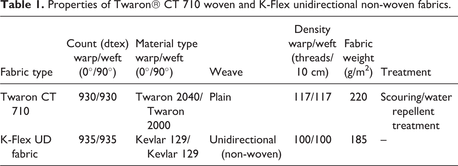
Twaron CT 710 woven fabric and K-Flex UD non-woven fabrics were used in this study. Properties of these two types of fabrics are given in Table 1. Surface images of the fabrics used in this study are presented in Figure 1(b) and (c).
Properties of Twaron® CT 710 woven and K-Flex unidirectional non-woven fabrics.
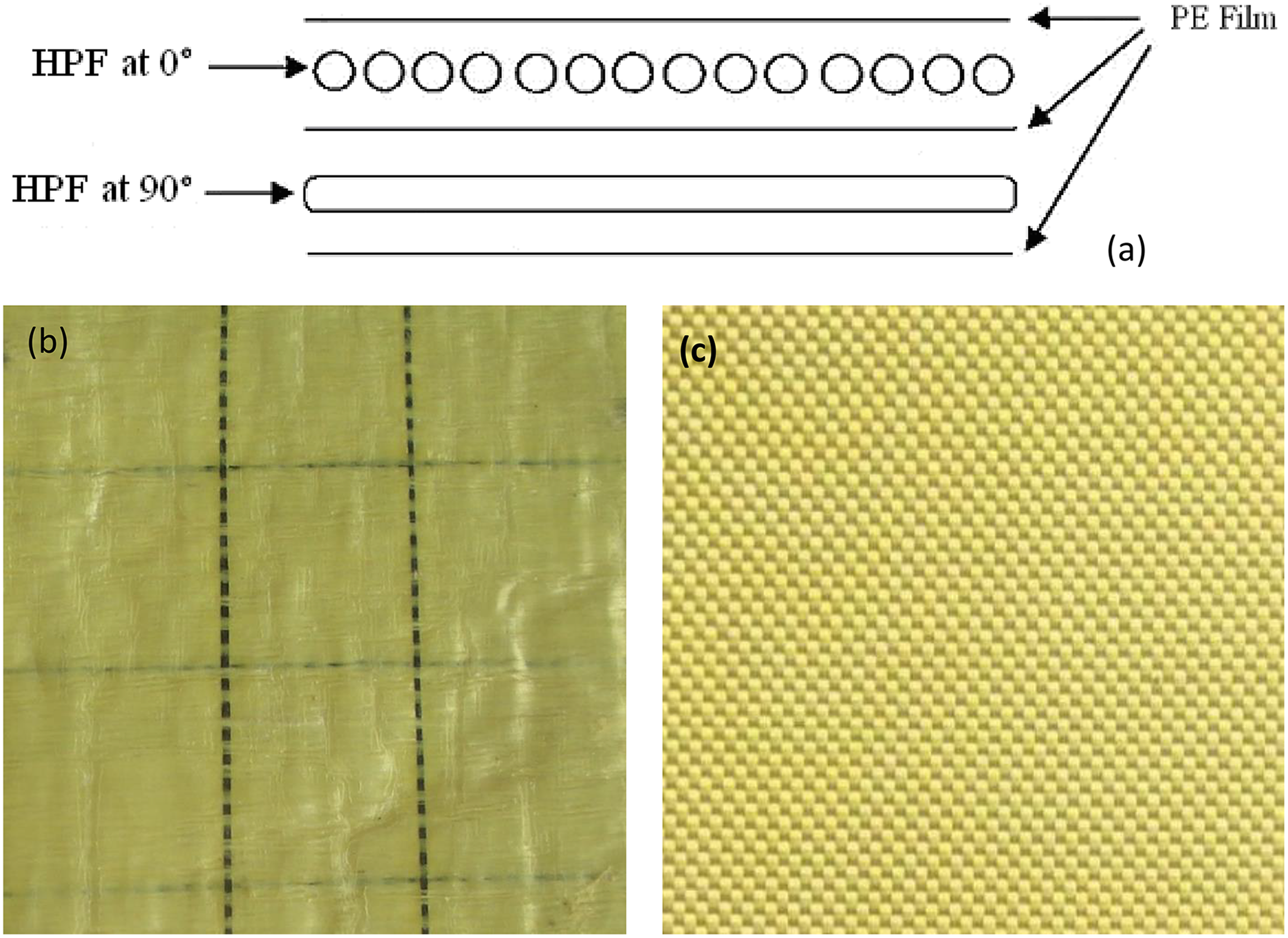
Schematic representation of unidirectional non-woven fabric structure (a) produced by placing yarns at right angle on top of each other (at 0° and 90°) and then by sticking them using a polyethylene film. View of K-Flex UD (b) and Twaron CT 710 woven fabric (c). HPF: high-performance fibres.
K-Flex is not a woven fabric structure. As shown in Figure 1(a), it is a UD non-woven fabric which is formed by placing Kevlar 129 yarns at right angle (at 0° and 90°) on top of each other and then by sticking them with the help of pressure and temperature using polyethylene films. No interlacing exists between the yarns perpendicular to each other and therefore K-Flex is a UD non-woven fabric structure. Because of this, there is no crimp in the yarns. 31,32
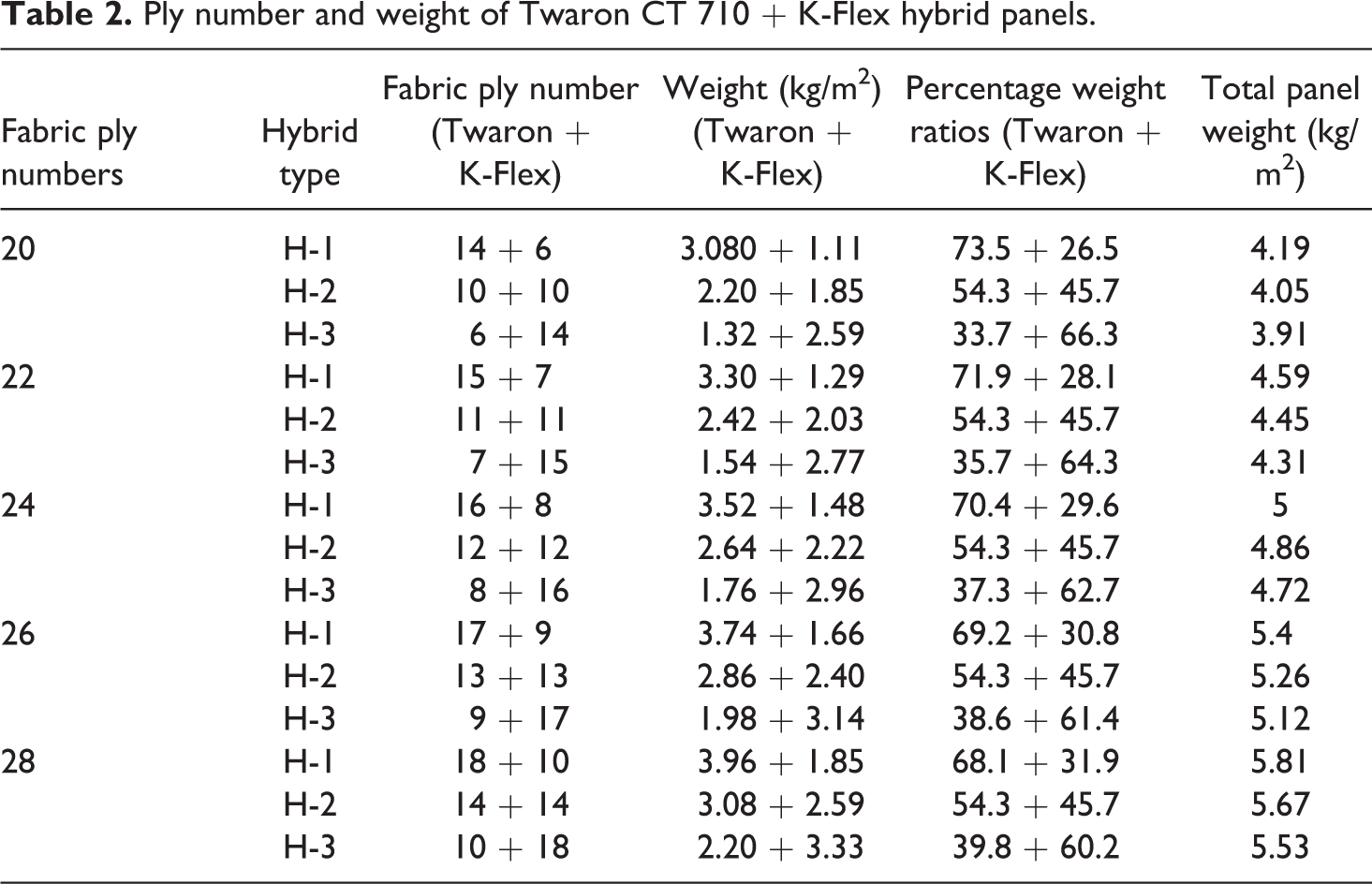
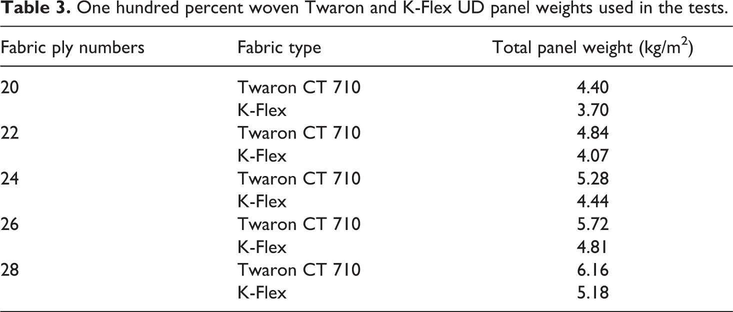
Hybrid panels used in this study are obtained by certain ratio combination of Twaron and K-Flex fabrics. Ballistic panels of dimensions 31 × 31 cm 2 were prepared by stitching the fabric plies at different ply numbers using high-twist para-aramid yarns. As stitching points are weak points in a non-woven structure, stitching was done at 20 mm from inside the edges of fabric layers. The weight and fabric ply number of panels are given in Table 2. Fabric layers were placed according to the order given in Table 2. Twaron fabric layers were placed on the front side and K-Flex fabric layers on the back side of each panel. Three different types of hybrid panels were formed using different ratios of Twaron and K-Flex fabric layers. The selected ratios of fabric ply number were 70% Twaron fabric–30% K-Flex fabric, 50% Twaron fabric–50% K-Flex fabric and 30% Twaron fabric–70% K-Flex fabric for H-1, H-2 and H-3 type of hybrid panels, respectively. Weight ratios of hybrid panels are also given in Table 2. Two types of reference panels, 100% woven Twaron fabric panels and 100% K-Flex UD Kevlar fabric panels, were used in the study. Weight and fabric ply number of these reference panels are given in Table 3.
Ply number and weight of Twaron CT 710 + K-Flex hybrid panels.
One hundred percent woven Twaron and K-Flex UD panel weights used in the tests.
Test apparatus
Ballistic testing was done according to NIJ 0101.03 level-II standard using test apparatus, as shown in Figure 2. According to this test scheme, there is 5 m distance between the exit point of the bullet from the gun barrel and the target. The bullet speed measuring unit is positioned at midpoint of the total distance.
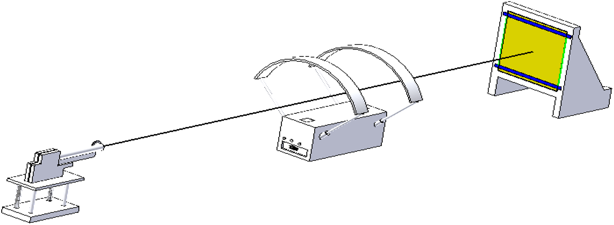
Test apparatus used in the experiments.
Shooting barrel and bullets
MP5 gun and 9 mm full metal jacketed round-nose projectile (FMJ RN) were used in shootings. Amount of gunpowder of the bullets was determined based on speed measurements in the preliminary tests. The core weight of the bullet was 8 g, whereas the total weight of the bullet including core, gunpowder and cartridge was 12 g. All the bullets were provided by Machine and Chemistry Industry Company of Turkey.
Chronograph
The speed of bullets was measured using Prochrono model chronograph provided by Competition Electronic Inc. (Rockford, USA) Chronograph has photoelectric principle and bullet speed is determined from its digital display after every shooting.
Backing material
Roma Plastilina No 1 ballistic clay supplied by EnvironMolds located in Summit USA, which is given in NIJ standards, was used as a backing material in this research. Clay was filled in a box as pointed out in the standard. The hardness of the backing material can show variability depending on temperature and environment conditions. For this reason, it is important to do the calibration. An iron weight with half sphere front tip, having 1 kg weight and 45 mm diameter, was used in the calibration.
Methods
Shooting tests
Shooting tests were carried out according to NIJ 0101.03 standard. Tests were conducted in both dry and wet conditions of ballistic panels. In wet tests, both front and back sides were subjected to water spray for 3 min and tests were conducted in the following 30 min. Before actual tests, preliminary tests were conducted to adjust the shooting precision. Targets were fixed with elastic tape on the front side of the backing material. Six bullets were shot on each sample as proposed in the standard. After shootings, depth and diameter of trauma formed on the backing material were measured. All the tests were conducted in Bursa Police College Shooting Polygon.
Determination of trauma depth and diameter
If the bullets cannot pass through the panels after shootings, a cavity is formed in the backing material with certain diameter and depth. This cavity is also called trauma depth. The depth of this cavity shows the effect of the bullet transmitted to the back side of a panel. If the ballistic panel spreads more energy, the cavity depth becomes lower and cavity diameter becomes larger. Otherwise, the cavity diameter would be lower and depth would be higher. After the shootings, both the depth and the diameter of each cavity were measured with a 1% precise micrometer. Later, a mould of cavity was prepared to obtain the cavity or trauma geometry.
Determination of energy absorption of samples
Formation of trauma geometry using moulds
Energy absorption capabilities of the ballistic panels were determined depending on trauma depth and diameter in the tests. Volume of trauma geometry was taken as a basis to find the energy absorption capacity of panels. Trauma geometry may show small differences from shooting to shooting. In this work, as the number of measurements is too high, trauma geometry was obtained depending on depth and diameter based on some assumptions.
Exact mould of trauma geometry was obtained for each test result using mould clay. Millimetrical divisions were formed on the mould clay by showing diameter axis by ‘x’ and depth by ‘z’. With the help of these millimetrical divisions, the depth values were obtained for each value of diameter. After that, the curves were fitted to these ‘x’ and ‘z’ values using Mapple 10 software. 33 Among polynom, rational polynom and Spline curve fitting techniques, Spline curve fitting technique was found to be the most suitable for the purpose of this research. 34,35 Figure 3 shows three-dimensional trauma shape obtained by turning Spline curve around ‘y’ axis.
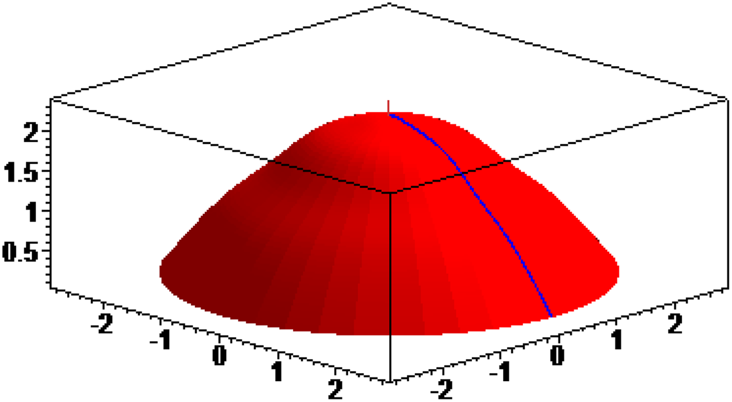
View of three-dimensional model of trauma obtained by a curve fitted using Spline curve fitting method.
Curves forming each trauma geometry were obtained by Spline curve fitting technique using Mapple 10 software. Data obtained from fitted curves were transferred to Inventor 10 CAD software, which is a solid modelling software, and volumes of trauma were calculated for each sample.
Calibration of backing material and determination of energy absorbed and transmitted to the back side
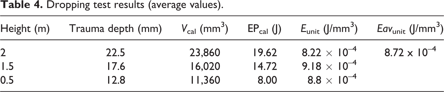
Calibration test was conducted to determine the trauma on the backing material created by the bullet. After the tests, energy required per unit volume of trauma on the backing material was calculated. In the tests, a cylindrical iron bar of 1 kg weight and 45 mm diameter with semi-spherical tip was dropped on the backing material from 0.5, 1.5 and 2 m heights, respectively, from a hollow tube. Trauma depth and diameter were measured for each case. The shape of trauma was taken as the semi-spherical shape of the tip of the iron bar. Trauma volumes were calculated using Invertor CAD software with the depth and diameter values obtained in this way. Unit trauma energies were calculated for 0.5, 1.5 and 2 m heights, and a linear relationship was found between unit volume trauma energy and dropping height. Results of the tests were found to be within the interval of the results recommended by NIJ 0101.03 standard for 2 m height. Tests were repeated five times for each height. Potential energy of the weight dropped was calculated using the following formula and the results are given in Table 4.
Dropping test results (average values).

where EPcal is the potential energy of the iron weight dropped (J), m is the weight of the iron bar having semi-sphere tip (kg), g is the gravitational acceleration (m/s 2 ) and h is the dropping height (m).
According to the data given in Table 4, it is seen that trauma depth changes linearly with the change in dropping height. According to NIJ standard, dropping test with 2 m dropping height is sufficient for calibration. But, dropping tests with different heights were also conducted in this work to approve the agreement of the test results with the results recommended by NIJ standard. With the test results, the calibration of the backing material was carried out and energy per unit volume (E unit) was calculated. Average unit volume energy was found to be 8.72 × 10⁻⁴ J/mm 3 . The unit volume energy was calculated using the following formula

where V cal is the volume of the trauma formed by weight dropped on the backing material (mm 3 ) and E unit is the energy absorbed by unit volume of trauma (J/mm 3 ). By establishing a relation between the trauma volume after shooting tests (V test) and trauma volume (V cal) created by a known potential energy (EPcal) on the backing material, energy absorbed and transmitted by the fabric is determined.
In the calculation of V test, the following relationship was obtained using polynomial curve, as shown in Figure 3. The volume of the body formed by turning the curve 360° around y axis is found using the following formula
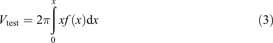
where V test is the volume of the trauma formed on the backing material due to shooting tests (mm3), f(x) is the equation of polynomial curve fitted using Spline curve fitting method and x is the radius of the trauma formed on the backing material (mm).
Trauma energy (E test) is found to be dependent on the trauma volume for each test as follows

Kinetic energy of the bullet just before it touches the fabric is as follows

where EKp is the kinetic energy of the bullet just before it touches the fabric (J), m is the mass of the bullet (kg) and v is the speed of the bullet (m/sec).
When panel layers prevent the bullet from passing to the other side, the majority of the energy is absorbed by fabric layers and spread on the fabric surface and the smaller part passes to the back side. The energy absorbed by the fabric (EAfabric) is calculated using the following formula

The energy creating the trauma is calculated by multiplying the unit volume energy obtained during calibration tests (8.72 × 10⁻⁴ J/mm3) by the trauma volume for each shooting. Energy absorbed by the fabric can also be calculated by subtracting this energy from kinetic energy of the bullet.
Results and discussion
Trauma depth and trauma diameter measurement results
All the samples were subjected to ballistic tests in both dry and wet conditions. The bullet speed for each test was measured using chronograph. Bullet speeds were recorded as an average of 370 ± 5 m/s. After each shooting test, the panel was checked to find out whether the bullet penetrated and passed through it or not. When the bullet did not pass through the panel, the depth and diameter of the trauma formed at the backing material were measured. The statistical significance of the measured trauma depth and diameter was measured by one-way analysis of variance with 95% confidence interval. It was found that fabric ply number and hybrid type had an effect on trauma depth and diameter and conditioning had some effect on trauma depth and no significant effect on trauma diameter. Tables 5 to 7 show the change in average trauma depth and diameter obtained from Student–Newman–Keuls (SNK) tests with respect to the fabric ply number, hybrid type used in panels and conditioning. Also, the results of 100% Twaron and 100% K-Flex panels, presented in the previous studies, 29,30 are given in tables for comparison purpose.
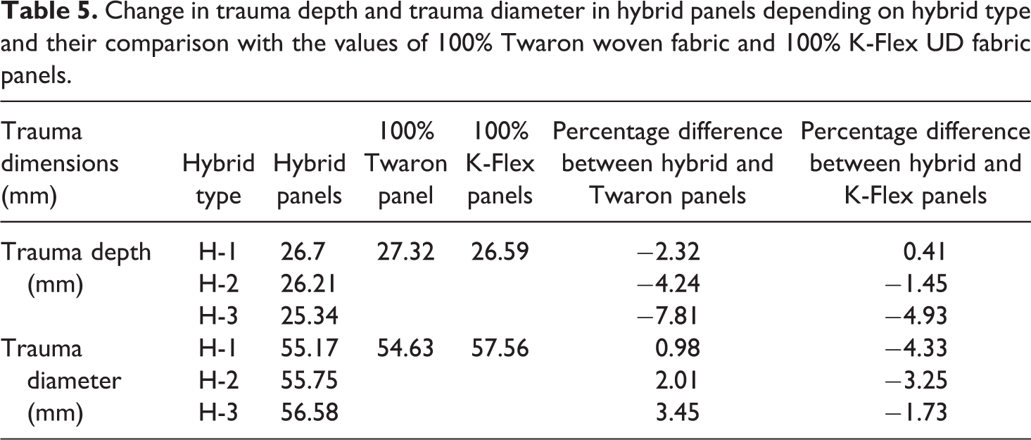
Change in trauma depth and trauma diameter in hybrid panels depending on hybrid type and their comparison with the values of 100% Twaron woven fabric and 100% K-Flex UD fabric panels.
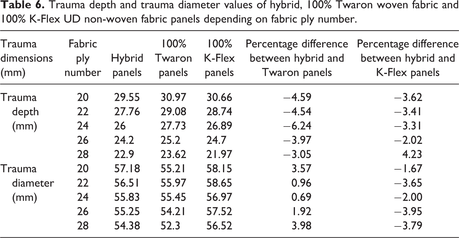
Trauma depth and trauma diameter values of hybrid, 100% Twaron woven fabric and 100% K-Flex UD non-woven fabric panels depending on fabric ply number.
Trauma depth and trauma diameter values of hybrid, 100% Twaron woven fabric and 100% K-Flex UD non-woven fabric panels depending on conditioning.
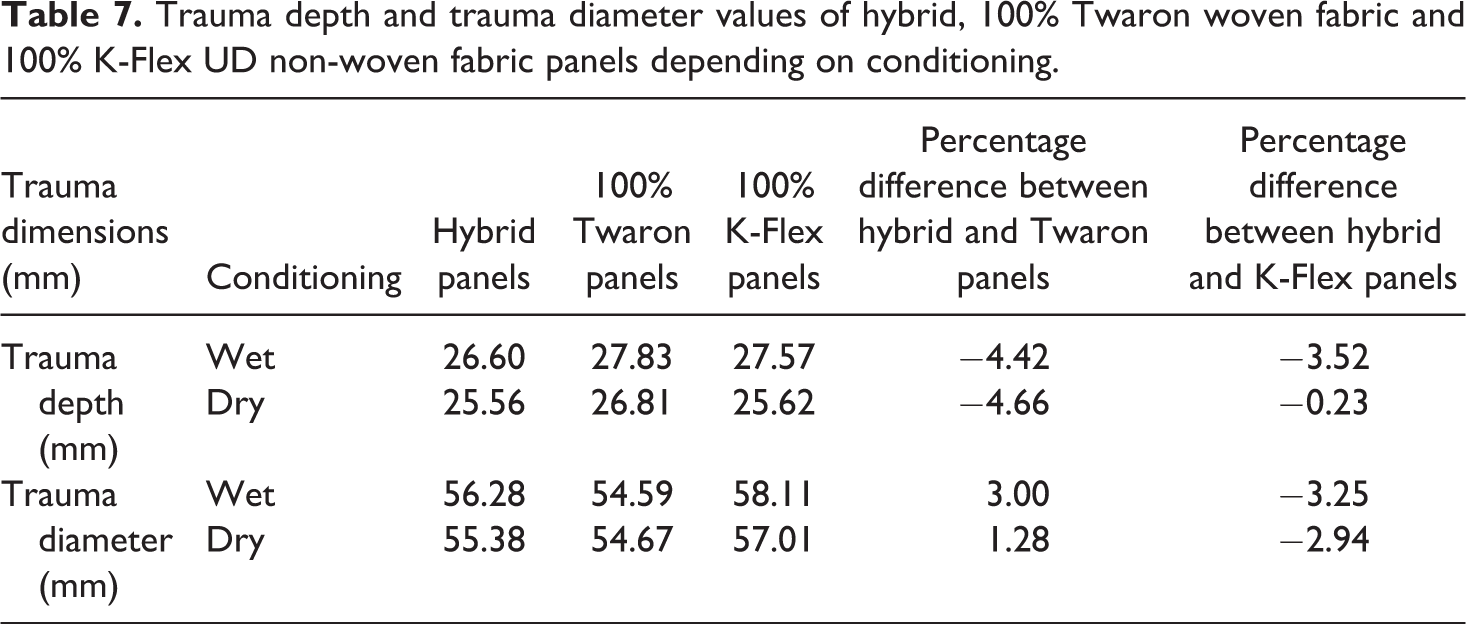
Table 5 shows the change in trauma depth and diameter for three different hybrid types. It is evident that the best trauma depth result is obtained by H-3 hybrid panel. The trauma depth in H-3 panel was found to be 3.3% and 5.1% lower than trauma depth in H-2 and H-1 panels, respectively. The lower trauma diameter is obtained for H-1 panel. No significant difference was found in trauma diameter between H-1 and H-2 panels. Trauma diameter in H-3 panel was found to be 2.5% higher than that of H-1 panel. In order to find the optimum hybrid panel type, it is necessary to take into account the energy absorbed and transmitted by the panel which is determined by the trauma volume. Table 5 also shows trauma depth and trauma diameter values for 100% Twaron woven fabric and 100% K-Flex UD non-woven fabric panels for comparison purpose. Trauma depth decreased in hybrid panels between 2.32% and 7.81% as compared to 100% Twaron woven fabric panels. Trauma diameter in hybrid panels decreased between 1.73% and 4.33% as compared to 100% K-Flex UD non-woven panel.
Table 6 shows the trauma depth and trauma diameter values of hybrid panels with different fabric ply numbers and comparison with the results of 100% Twaron woven fabric and 100% K-Flex non-woven UD fabric panels. It is clear that trauma depth decreases with the increase in fabric ply number. Around 22.5% decrease in trauma depth is observed when the fabric ply number is increased from 20 to 28 in hybrid panels. It is also seen that trauma depth results in hybrid panels are better than 100% K-Flex UD non-woven and 100% Twaron woven fabric panels. Furthermore, trauma diameter decreases with increasing fabric ply number. Trauma diameter is decreased to about 4.9% when fabric ply number increased from 20 to 28 in hybrid panels. Trauma diameter, in hybrid panels, was found to be 0.69–3.98% higher than 100% Twaron woven fabric panels. But hybrid panels have 1.67–3.95% lower trauma diameter as compared to 100% K-Flex UD non-woven fabric panels which is an advantage for hybrid panels.
Table 7 shows trauma depth and trauma diameter values in both dry and wet conditions for different panel types. It was shown in the previous studies 29,30 that the wetting process reduced ballistic resistance in K-Flex UD non-woven fabric panels and improved the ballistic performance of Twaron woven fabric panels. In dry state, K-Flex UD non-woven fabric panels showed better ballistic performance than Twaron woven fabric panels due to their lower weight and lower trauma depth. On the other hand, wetting significantly reduced the ballistic performance of K-Flex UD non-woven fabric panels. In hybrid panels, a 4.06% increase in trauma depth was observed in wet panels as compared to dry panels. According to the average values obtained from SNK tests, in wet conditions, hybrid panels showed 3.52% and 4.42% improvement in trauma depth as compared to 100% K-Flex and 100% Twaron fabric panels.
Change in trauma depth and trauma diameter with the increase in the panel weight of hybrid samples for dry test conditions is shown in Figure 4. Results show a decrease in both trauma depth and trauma diameter with increasing panel weight.
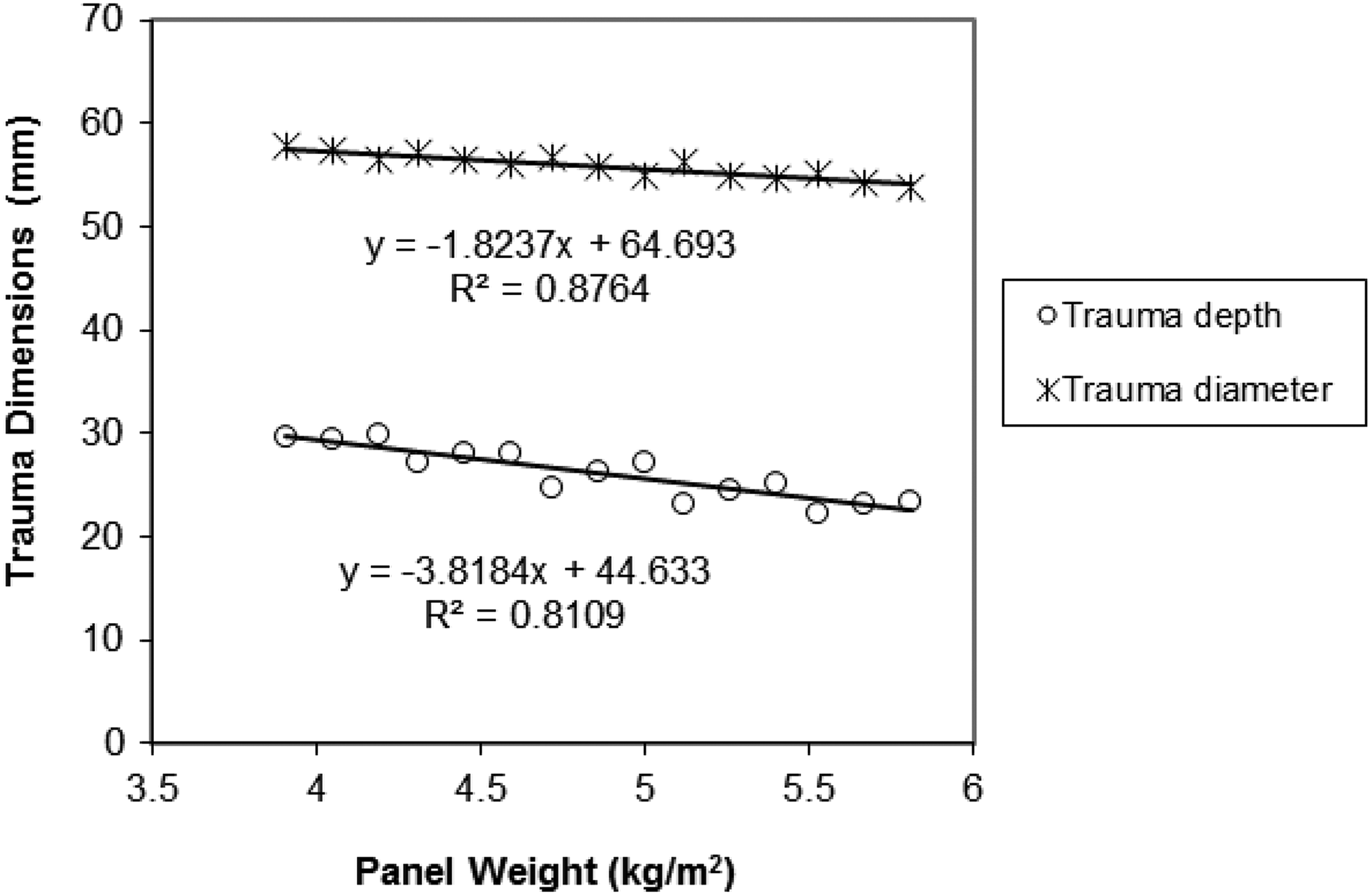
Change in trauma depth and trauma diameter in hybrid panels with respect to panel weight for dry test conditions.
Ballistic energy and determination of energy absorption of panels
During ballistic impact, a shock wave is produced on ballistic panel due to kinetic energy of the bullet. Most of this energy is absorbed by the fabric layers, and the remaining is transmitted to the back of the panel and forms a trauma.
Average values of the transmitted and absorbed energies by the panels are given in Tables 8 to 10 depending on hybrid type, fabric ply number and conditioning. As the weight of the bullet is constant, the energy affecting the panels changes in proportional to the bullet speed. Bullet speed can show variations within certain tolerances from shooting to shooting. Therefore, the kinetic energy of the bullet becomes different for each shooting.
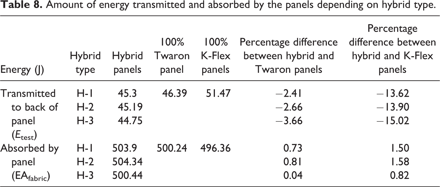
Amount of energy transmitted and absorbed by the panels depending on hybrid type.
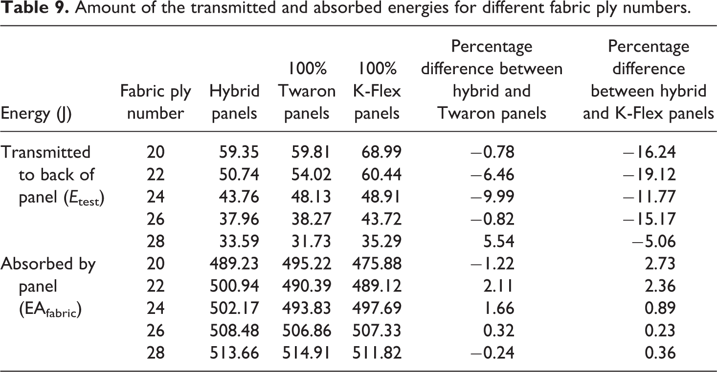
Amount of the transmitted and absorbed energies for different fabric ply numbers.
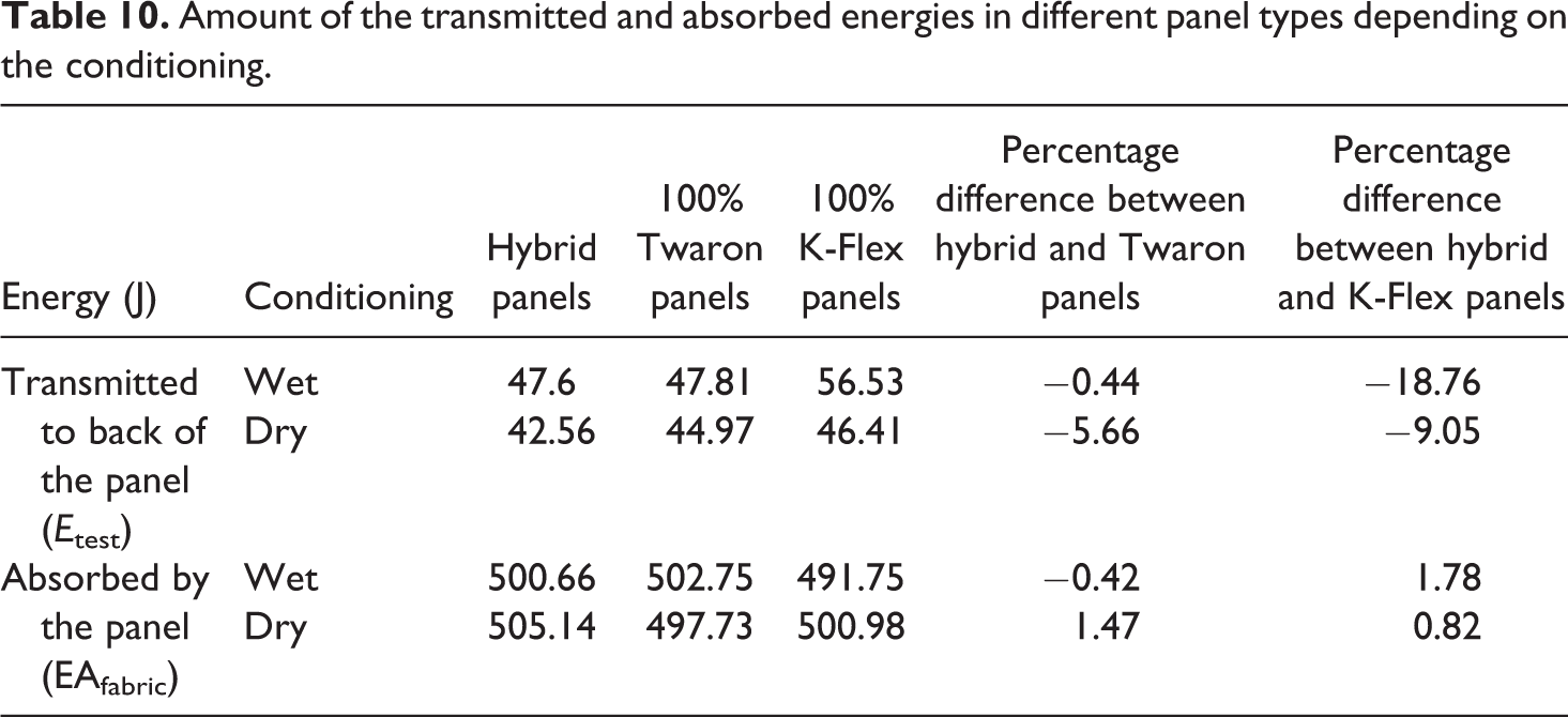
Amount of the transmitted and absorbed energies in different panel types depending on the conditioning.
Analysis of the data in Table 8 shows no significant difference in the absorbed energy between hybrid panels, 100% K-Flex UD non-woven fabric and Twaron woven fabric panels. But, a significant reduction in the energy transmitted to the back of the panel was achieved for hybrid panels as compared to 100% K-Flex UD non-woven fabric panel. A 15% decrease in the energy transmitted to the back of the panel was obtained with H-3-type hybrid panel as compared to 100% K-Flex UD non-woven fabric panel. Although the reduction in the energy transmitted to the back of the panel is equal to the increase in the energy absorbed by the panel, much larger values of the absorbed energy make percentage change very small. Thus, this makes the percentage change in the absorbed energy insignificant.
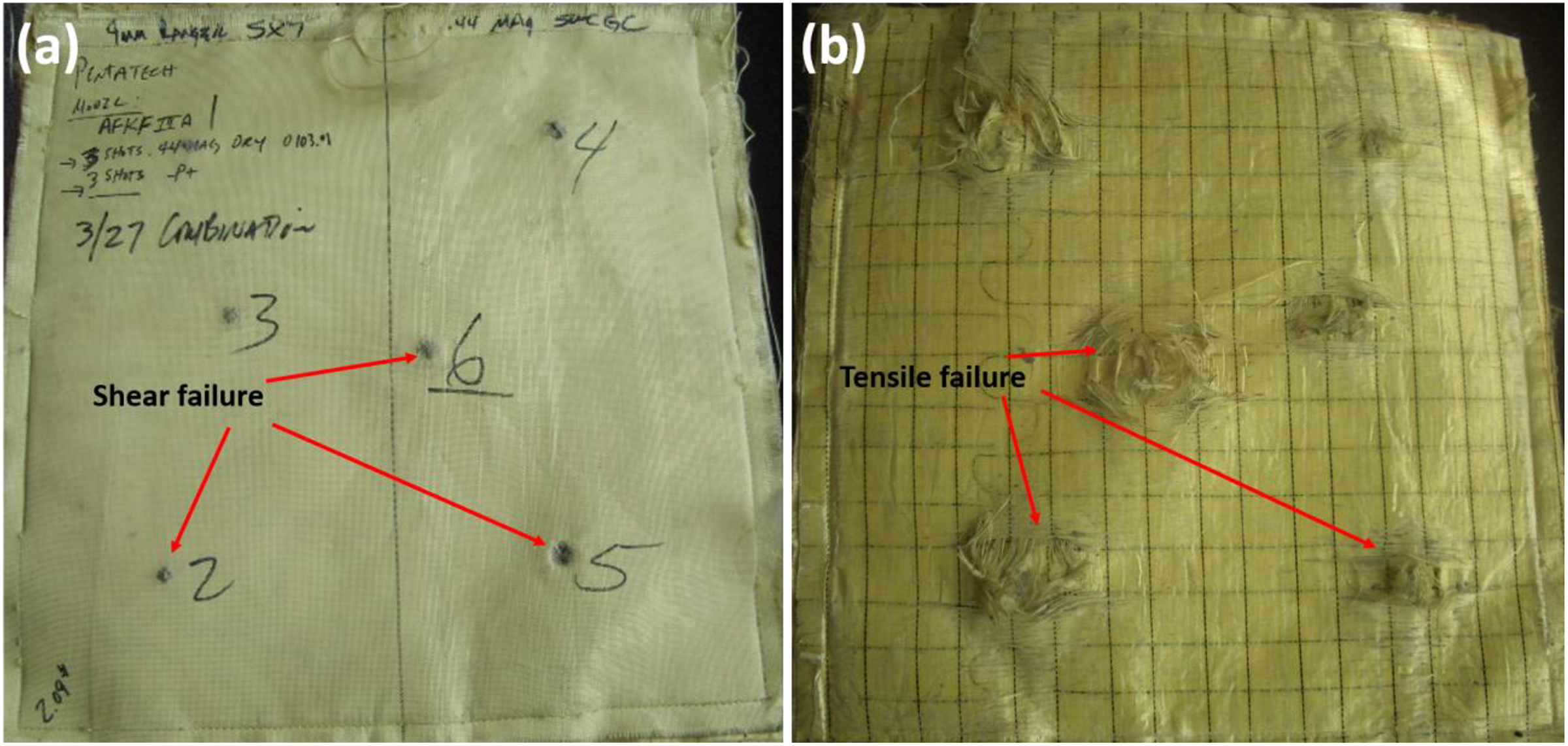
Figure 5 shows the change in the absorbed and transmitted energies with respect to panel weight for dry test conditions. The absorbed energy increases with a positive slope, whereas the transmitted energy decreases with almost the same negative slope with respect to panel weight. This means that the decrease in transmitted energy is absorbed by the panel. The absorbed energy per unit weight was 102, 105.1 and 107.5 J/kg for H-1, H-2 and H-3-type hybrid panels, respectively. This result shows the advantage of H-3 type of hybrid panel. The possible reasons for these findings may be explained by the fact that hybrid panels with woven fabrics are close to impact point and UD structures as rear layers tend to absorb more energy of the bullet, forming less trauma depth and diameter at the back. This is because the fabric layers on the front side of ballistic panel tend to fail in shear, whereas the fabric layers on the back side are likely to be broken in tension. Moreover, woven fabrics provide better shear resistance and UD structures exhibit better tensile resistance. 36 In hybrid panels, a suitable combination of woven fabric at the front and UD fabric at the rear can give better ballistic performance on unit weight basis which is in our case 30% Twaron fabric and 70% K-Flex UD fabric panels. As shown in Figure 6, shear deformation of fibres on the front face and fibre breakage in tension on the back side are the visible failure modes in hybrid panel.
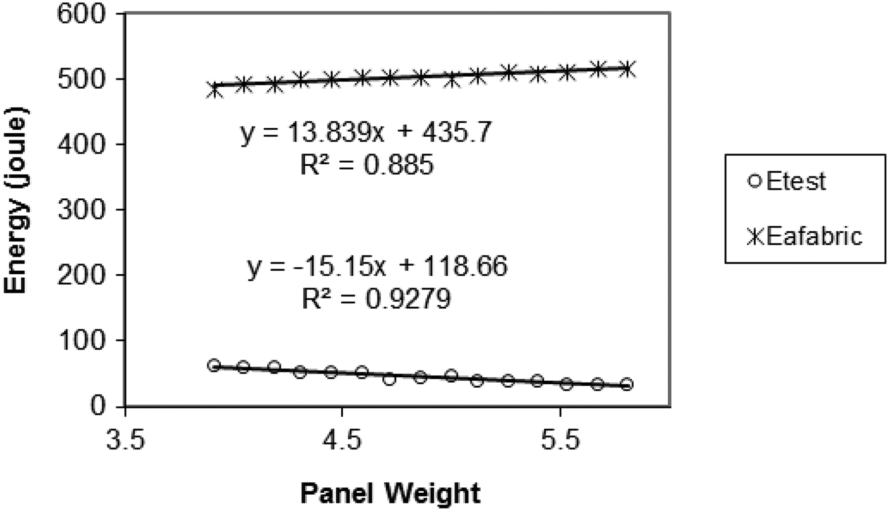
Change in the energy absorbed (EAfabric) and energy transmitted (E test) by the panels with respect to panel weight for dry test conditions.
Hybrid panel after ballistic test (a) front side and (b) back side.
Figure 7(a) shows the front face deformation of 100% aramid woven fabric. 29 There are so much wrinkles and shear deformation at the warp and weft yarns because of yarn pull-out during ballistic impact. It can be observed that the size of damage around the point of impact on the front side is larger for 100% aramid woven fabric than 100% K-Flex UD panel, as shown in Figure 7(c), because of so much yarn pull-outs from the fabric structure. Figure 7(b) shows the back face deformation of 100% aramid woven fabric. 29 There is so much plugging and bulging deformation on the back face because of the ballistic loading. But, fibre stretching and fibrillation were not observed.
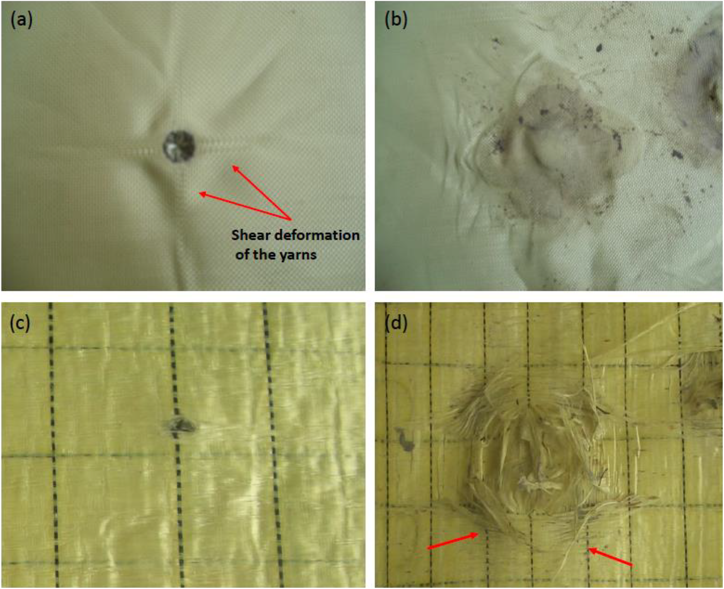
Front side and back side deformations of the 100% woven fabric (a and b) and 100% K-Flex UD fabric panels (c and d).
Figure 7(c) shows the front face deformation of the 100% K-Flex UD panel. There is no visible shear deformation around the impact point. Although at the back face no penetration, there are too much deformation as yarn breaking since impact stress on the yarn (Figure 7(d)). Because there is no crimp between the yarns, all stresses are applied to the yarns. So there is too much fibre stretching and fibrillation deformation on the back face because of the tensile loading during ballistic impact. Figure 8 proves the fibre stretching and fibrillation deformation at the back face of the 100% K-Flex UD panel.
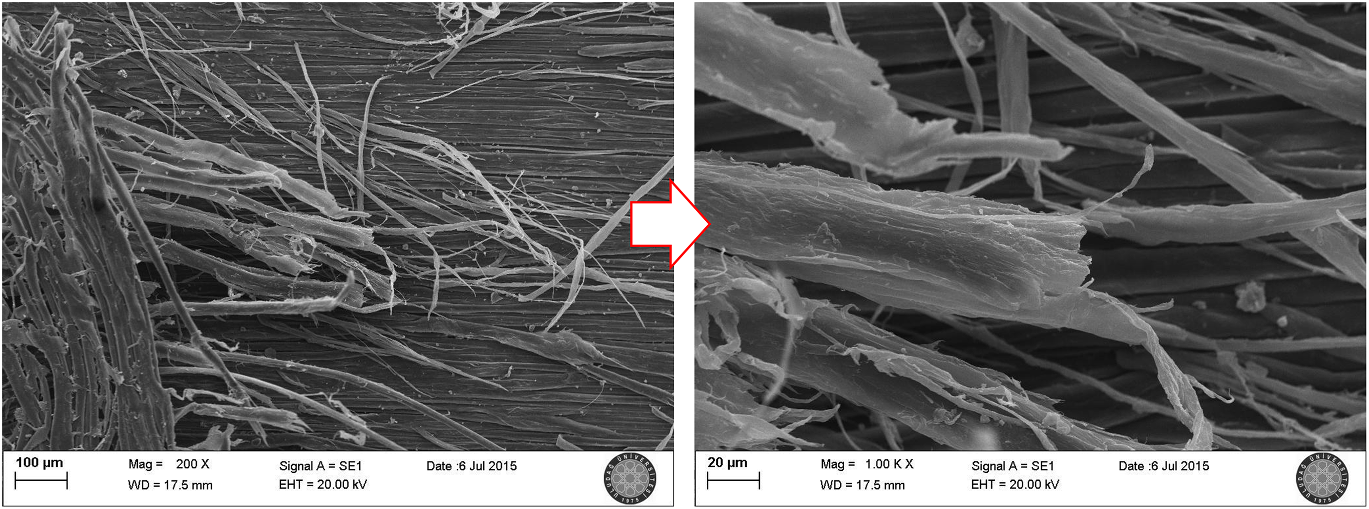
SEM images of the back face of the 100% K-Flex fabric panels around the impact points. SEM: scanning electron microscope.
Impact stress spends its energy to break the yarns. 30 This situation increases the energy absorption capacity of the ballistic panel.
Hybrid panels and 100% K-Flex panels almost have similar back face deformation. But, at hybrid panels, panel distortion is less compared with hybrid ones because of woven fabric rigidity.
The main reason for the shear deformation of woven fabrics is the crimp between the warp and weft yarns (Figure 9(a)). The stress arising due to ballistic impact causes tension along the fabric plane as well as in the vertical direction of the fabric plane due to crimp in yarns. This causes the yarns to displace towards the back of the fabric and therefore higher trauma depth is created. 14
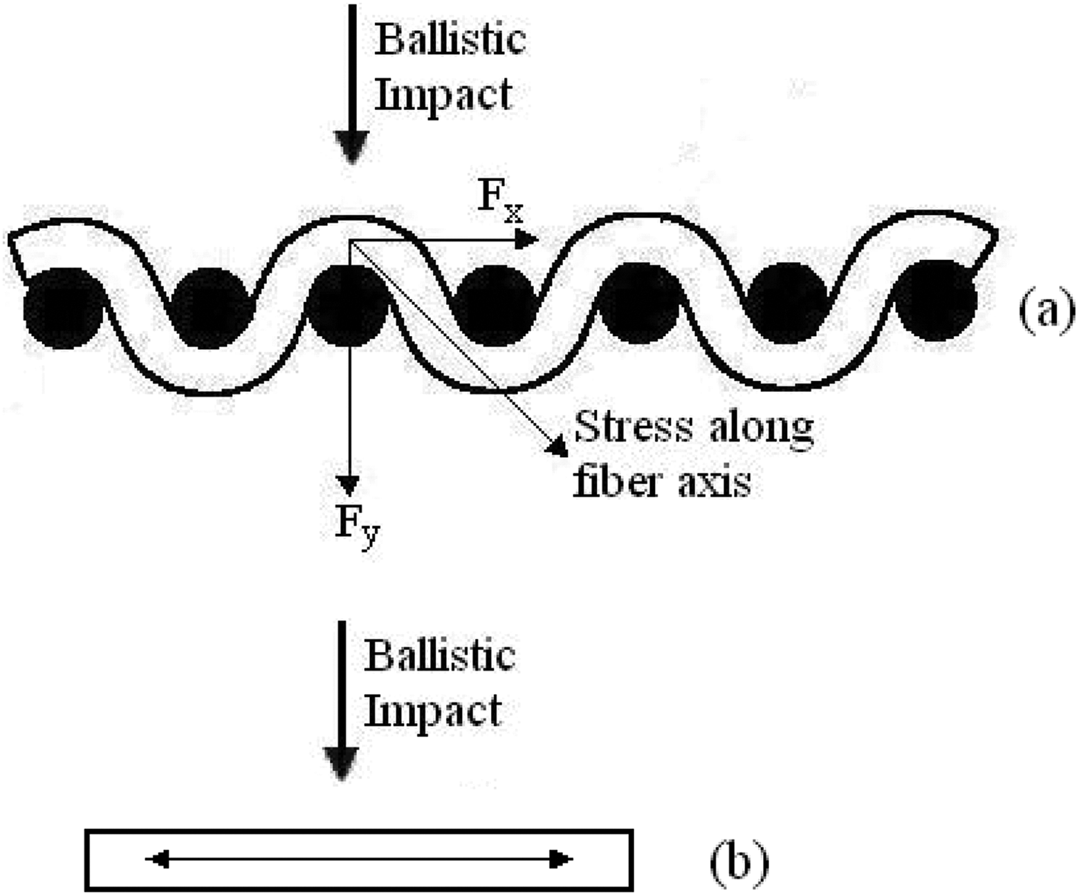
Stress formation behaviour of (a) woven and (b) unidirectional non-woven fabric structures after a ballistic shock.
But as shown in Figure 9(b), in the UD structure, the stress arising due to ballistic impact is spread in the fabric plane. It is expected in this case that the majority of shock wave is spread in the fabric plane and the energy transmitted to the back of the fabric decreases. Therefore, lower trauma depth is expected to occur.
Table 9 shows the energy absorbed and transmitted by the panels for different fabric ply numbers. The energy transmitted to the back side of the panel decreases with increasing fabric ply number. About 43% decrease in the energy transmitted to the back side of the panel was observed when the fabric ply number in the hybrid panels increased from 20 to 28. Around 4.9% increase in the absorbed energy was noted in the hybrid panels with the increase in the fabric ply number from 20 to 28. The difference between the percentage absorbed and transmitted energies is due to the difference between the amount of the absorbed and transmitted energies, as explained above. With hybrid panels, around 10.0% and 19.0% decrease in the energy transmitted to the back of the panel was recorded as compared to 100% Twaron woven fabric and 100% K-Flex UD non-woven fabric panels, respectively.
Table 10 shows the energy absorbed and transmitted by the panel depending on dry and wet conditions of the panels. In wet hybrid panels, around 18.76% less energy is transmitted to the back as compared to 100% K-Flex UD non-woven panels. Moreover, in dry hybrid panels, almost 5.6% and 9.05% less energy is transmitted to the back as compared to 100% Twaron and 100% K-Flex UD non-woven fabric panels, respectively.
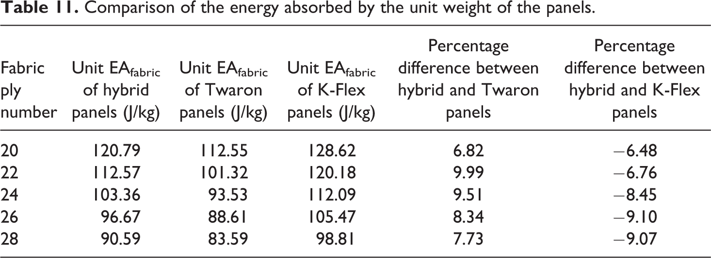
The absorbed energy per unit weight is shown in Table 11. It is clear that hybrid panels absorb about 6.82–9.99% more energy per unit weight over 100% Twaron woven fabric panels, but they have no specific advantage over 100% K-Flex UD non-woven fabric panels. This is thought to be due to the lighter weight of 100% K-Flex UD non-woven fabric panels.
Comparison of the energy absorbed by the unit weight of the panels.
Conclusion
In this research, the ballistic performance of hybrid panels formed using certain combinations of woven (Twaron CT 710) and UD non-woven K-Flex para-aramid fabrics is investigated and compared with 100% Twaron CT 710 woven fabric and 100% K-Flex UD non-woven fabric panels. The following conclusions are drawn: Best ballistic performance is shown by 70% K-Flex non-woven fabric–30% Twaron woven fabric hybrid type. Better trauma depth and diameter values are obtained for hybrid panels as compared to 100% K-Flex UD fabric and 100% Twaron fabric panels. The trauma depth in hybrid panels was 4.48% and 1.63% less as compared to 100% Twaron woven and 100% K-Flex UD fabric panels, respectively. There was no significant difference in trauma diameter between the hybrid and 100% Twaron woven panels, but 3.0% less trauma diameter in hybrid panels was observed as compared to 100% K-Flex UD fabric panels. In wet conditions, the trauma depth of hybrid panels was less as compared to both 100% Twaron woven and 100% K-Flex UD fabric panels. No significant difference was observed in trauma diameter between hybrid panels and 100% Twaron woven fabric panels. However, 3.25% less trauma diameter was seen in hybrid panels as compared to 100% K-Flex UD fabric panels. In hybrid panels, the energy transmitted to the back side of the panels was found to decrease as compared to 100% Twaron woven and 100% K-Flex UD fabric panels. More energy per unit weight in hybrid panels was absorbed as compared to 100% Twaron woven fabric panels, and no significant difference was realized as compared to 100% K-Flex UD fabric panels.
Footnotes
Declaration of Conflicting Interests
The author(s) declared no potential conflicts of interest with respect to the research, authorship, and/or publication of this article.
Funding
The author(s) received no financial support for the research, authorship, and/or publication of this article.