
Abstract
The urgent need for flexible strain sensors that are both aesthetic and functional is addressed, given the rapid development of smart wearable technology and the improvement of material level. To achieve this, silver-plated yarns based on nylon and nylon wrapped spandex were directly knitted into the sensor using cross-knit intarsia and plating technology. Five samples, with varying percentages of loops and tuck loops, were designed. The results indicated that the sensor demonstrated a GF of 2.80 kPa−1 at the Lx-axis and 3.67 kPa−1 at the Ly-axis, showing good repeatability during 1000 cycles of stretch/release. Moreover, it exhibited fast responsiveness, enabling it to discriminate between different rates of stretch. The sensor's potential for application in wearable smart medical monitoring was demonstrated by its ability to be embedded in garments for joint motion monitoring. These findings collectively suggest that the designed knitted strain sensor holds promising potential for use in the field of wearable smart medical monitoring.
Keywords
Introduction
Wearable flexible electronic devices, which integrate fabric and electronic information technology, have become a flourishing intersection of technologies in various fields due to the progress of time. These devices have gained significant attention from researchers across many disciplines because of their vital role in human-computer interaction, motion monitoring, and postoperative rehabilitation therapy.1–3 Within wearable electronic devices, flexible sensors serve as the “core component” and play a crucial role in signal transmission.4–7 Notably, resistive strain sensors have been extensively studied due to their simplicity, reliability, wide detection range, high sensitivity, and ease of integration.8–10
Fabric-based flexible sensors depend heavily on the fabric structure and the conductive material for optimal performance. Knitted fabrics, distinguished by their unique loop structure, offer excellent softness and a wide stretch range compared to other fabric types like woven and nonwoven fabrics. Therefore, choosing knitted fabrics as the flexible base material significantly enhances the wearing comfort and working strain range of the sensor.11–13 Currently, a wide array of knitted sensors is developed using conductive polymer materials, such as graphene,14–16 MXene,17–19 polypyrrole,20,21 PEDOT: PSS,22,23 and nano-silver.24,25 Techniques like coating, impregnation, and printing are employed to attach these substances to the fabric's surface or internal parts. These methods ensure that the prepared sensors exhibit excellent sensitivity, fast response, and high stability. However, the rough surface of the fabric often hampers complete fusion between the fabric and the conductive substance, causing flaking during usage, which ultimately affects sensor performance.
Smart wearable devices that combine aesthetics and functionality can accelerate the process of successful commercialization. To achieve this, researchers have explored various approaches, including integrating conductive yarn directly into the inside of the fabric by knitting. This method allows the conductive material to enter the internal structure of the fabric, maximizing the integration with the structure and improving the sensing performance by utilizing the large strain tensile properties of the knitted fabric. Many investigations have been conducted to analyze resistive sensors based on different fabric stitches, with particular emphasis on the electro-mechanical properties of single plain stitch and rib stitch.26–31 The common feature of these structures is that they only comprise loop units. Additionally, studies have explored single pique conductive fabrics containing tuck loop units, 32 which have better air and moisture permeability compared to single jersey stitch and rib stitch. This feature makes fabrics with tuck loop units more suitable for human motion detection, as they can effectively guide and release the heat produced by the body during movement. Furthermore, altering the loop and tuck loop ratio in the fabric structure can result in diversified structures, bringing about distinct appearance effects.
It is worth noting that early research primarily focused on conductive yarns, as metals are known for their excellent conductivity. A typical example of fabric sensor material is stainless steel yarn, which boasts good conductivity but poor stiffness and conductive stability. However, due to its shortage, its application is limited in the field of wearable smart devices. Consequently, it is more advisable to utilize silver-plated nylon yarns, which offer greater stability and performance in the development of wearable flexible sensors. 33 Elastic yarns have also been found to have a positive impact on sensor performance, with the wrapped type of elastic yarns offering higher sensitivity. 34 However, the production of wearable flexible sensors is currently constrained by the limitations of weft knitting machines. These machines can only produce fabrics with larger dimensions, resulting in longer yarn travel and reduced efficiency. Furthermore, this knitting process increases the production time and yarn volume, thereby increasing the preparation cost of fabric-based flexible sensors. To address these issues comprehensively, the use of flat knitting machines is suggested for the preparation of fabric sensors.35–37
In this paper, we demonstrate the promising application of silver-plated yarns and elastic yarns in the field of wearable medical monitoring devices. The sensors are knitted using the intarsia stitch and the plating technology, allowing for seamless embedding in the fabric. Moreover, the inclusion of the tuck loop structure not only enhances the variety and aesthetics of the sensor structure but also contributes to improved comfort and sensing properties. We further characterize the sensor, emphasizing its simplicity of fabrication and low assembly costs. Additionally, we showcase the application of the sensor in human motion monitoring, providing evidence of its potential in the aforementioned field.
Experimental section
Materials
The conductive yarn is 1 × 200D nylon filament with silver plated layer, which is supplied by Zhiyuanxiangyu Co., Ltd (Qingdao, China). The elastic yarn is 1 × 110D yarn with a 40D spandex core yarn and 70D nylon yarn wrapped outside, supplied by Jiangsu Grete Textile Co., Ltd (Zhenjiang, China). The non-conductive yarn is 1 × 600D polyester purchased from Jiangsu Hengli Chemical Fiber Co., Ltd (Suzhou, China).
Design and preparation of sensor structures
The fabric structure is designed with process parameters by M1 software and then imported to the STOLL CMS530 series flat knitting machine. The specific manufacturing process is shown in Figure 1. The diagram of the specific manufacturing process for sensor.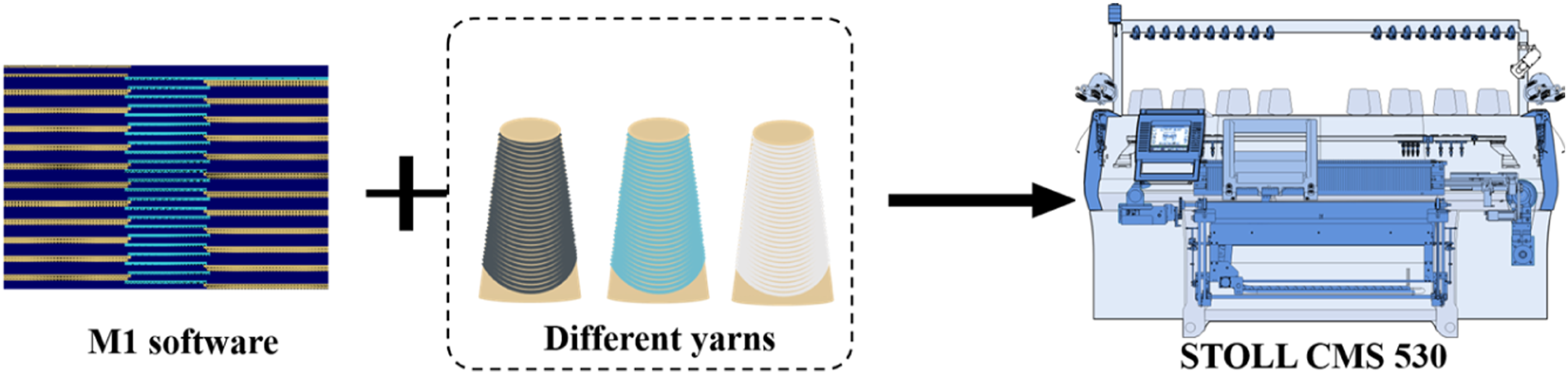
As shown in Figure 2, the intarsia stitch is a technique that combines needle selection with yarn exchange, using two or more different color yarns to knit flower blocks. These blocks are then joined in the longitudinal direction to create a patterned fabric. Unlike jacquard, intarsia stitch does not produce a floating line or sesame dot effect on the backside of the fabric. During the knitting process, the fabric surface is divided into three regions by the intarsia stitch: non-conductive region I, conductive region, and non-conductive region II. The conductive area is formed by the yarn carriers 2 and 4, where yarn carrier 2 guides the silver-plated yarn to appear on the fabric's surface while yarn carrier 4 hides the elastic yarn on the fabric's backside. Yarn carriers 1 and 3 are threaded with low-stretch polyester yarn. In the first step (step 1), yarn carriers 1, 2, and 3 are spaced at the same distance and move simultaneously towards the left to feed the yarn into the needle for knitting. Yarn carrier 4, serving as the plating yarn carrier, is positioned next to yarn carrier 2. When yarn carrier 3 finishes knitting non-conductive area II, it creates a tuck loop to the left to connect the conductive area with non-conductive area II. The subsequent conductive and non-conductive regions are connected using the same method as described above. In the second step (step 2), while knitting the second course, the yarn carrier moves in the opposite direction from the previous step, and the connection between the different regions is achieved through a tuck loop. This process allows for seamless integration of conductive and non-conductive areas. Knitting process diagram of intarsia stitch and fabric effect.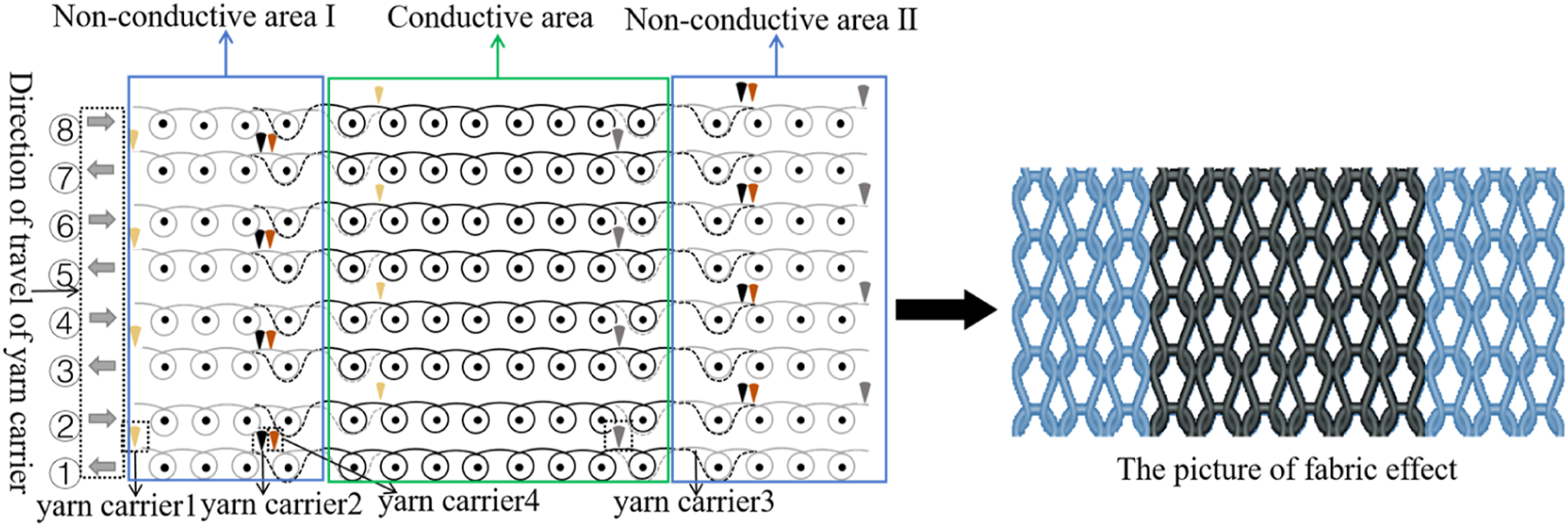
On this basis, the elastic yarn is introduced into the sensing fabric in combination with the plating technology to improve the sensing performance of the fabric. In the knitting process, the conductive yarn and the elastic yarn are threaded into different carriers as two independent yarns and fed into the identical needle on the machine at the same time. As shown in Figure 3, the silver-plated yarn always covers the surface of the elastic yarn, which improves the sensing performance of the fabric by adding the elastic yarn and ensures the uniformity of the silver-plated yarn on the sensor’s surface. The diagram of the sensor preparation process.
Introduction of samples.

In addition, Figure 4 shows the physical fabricating structure. Sample A1-A3 is a single jersey fabric, which is designed by changing the relationship between the percentage of loop and tuck loop. The presence of the tuck loop gives a twill effect on the surface of the fabric. Moreover, the mesh was produced at the twill to increase the breathability of the fabric and improve the comfort of the human body. The width of the twill was influenced due to the different content of tuck loops. The higher the content, the wider the twill. Besides, sample A4 and sample A5 are double-sided fabric. The structure of the sensor was designed by changing the content of the tuck loop on the front and back needle beds of the flat knitting machine. Different content of tuck loop caused the front and back sides of these samples to show different fabric effects. The diagram of the fabric structure, (a) sample A1; (b) sample A2; (c) sample A3; (d) sample A4; (e) sample A5.
The five kinds of knitted conductive fabrics are shown in Figure 5. Large mesh structures are formed in the area covered by the tuck loop unit, showing mesh effect in morphology. And with the increase of tuck loop content, the number of mesh also increases. Due to the special design of the structure, the mesh presents a continuous plain twill effect on the surface of the fabric, which enlarges the aesthetic degree of the fabric. It provides the possibility for the development of sensors with aesthetic value. For double-sided fabric sample A4-A5, the front and back of the fabric show different appearance effects due to the different loop content of the front and back of the needle bed. The fabric with more loop content shows a wider transverse effect. And the yarn needs to be knitted back and forth between the front and back bed, so the two sides of the fabric share the total number of longitudinal lines, so only five longitudinal lines are shown on each side of the fabric. Furthermore, the silver-plated yarn will leave a length of yarn beyond the intarsia area, which can be used as a wire to be connected to a test instrument to evaluate its performance. Actual picture of five conductive fabric, (a) sample A1; (b) sample A2; (c) sample A3; (d) sample A4; (e) sample A5.
Sensor performance test methods
The resistive variation of the sensors was tested in the range of 0%-100% strain using a Mark-10 tensiometer (Beijing Jipin Times Technology Co., Ltd., Beijing, China). The sensors are designed to study the electrical properties of fabric by detecting changes in its degree of deformation. This deformation causes the contact state of the yarn inside the sensor to change accordingly, leading to variations in the output electrical parameters of the sensor. These changes can be captured by an external device, thus completing the sensing and monitoring processes. The resistance change of the sensors was monitored and recorded using a digital multimeter, specifically the RIGOL DM3068 (Suzhou Puyuan Precision Technology Co., Ltd., Jiangsu, China). Fabric-based flexible sensors are often integrated into garments to create intelligent flexible devices for monitoring human activities. In order to accurately measure the force applied to the human body, it is crucial to study the transverse and longitudinal tensile electro-mechanical properties of the sensor. Furthermore, during physical exercise, the human body generates sweat and releases heat through the skin's surface. To maintain a comfortable balance for the body, it is important for the fabric to effectively transport moisture and enable air permeability. The fabric's air permeability and moisture permeability were evaluated based on the standards GBT 5453-1997 and GBT 12704.2-2009, respectively.
Results and Discussions
The transverse and longitudinal tensile electro-mechanical properties
The sensing mechanism of a flexible knitted resistive sensor is that during stretching, changes in the structure lead to changes in the contact state between the loop, as well as the loop will undergo transfer.
38
The tensile electro-mechanical properties in both directions of the strain sensor are demonstrated by simulating the relationship between strain and sensor resistance during the stretch-release process. Stretch along the transversal direction is defined as Lx-axial stretch and stretch along the longitudinal row direction is defined as Ly-axial stretch. This phenomenon makes the ratio of contact resistance and yarn resistance increase or decrease, thus changing the output resistance magnitude to achieve sense. As shown in Figure 6(b), the contact resistance is generated at the contact point. Ideally, since the yarn itself is a conductor, it conforms to the resistance law R=ρl/s, where R represents the yarn resistance, ρ is the resistivity, and s is the yarn cross-sectional area.
39
Illustration of, (a) The diagram of the testing process (b) Changes in the fabric structure before and after stretching; (c) The diagram of the Lx-axis tensile strain resistance; (d) The diagram of the Ly-axis tensile strain resistance.
The knitted strain sensor was fixed at both ends of the Mark-10 tensioner jacket along the vertical ground plane, as shown in Figure 6(a). The initial spacing was set as 50 mm, and the knitting sensor was stretched at 50 mm/min, within a range of 0%–100%. This sensor was connected to the digital multimeter by two metal collets (red and black wires), forming a complete energized circuit. Figure 6(c) and (d) present the tensile strain resistance curves for the five different stitches. It is evident that there is a similar trend of increasing resistance with strain for the five stitches. Furthermore, the initial resistance of the fabric decreases progressively as the proportion of the tuck loop increases. The reason behind this is that the presence of tuck loops enhances the contact area between conductive yarns, thereby increasing the number of circuits in the fabric structure as a whole. Consequently, the total resistance of the fabric is reduced.
The fabric resistance first increases and then decreases with increasing strain when Lx-axial stretching is applied to the fabric. In the initial stage of fabric stretching, the loops are closely fitted to each other due to the presence of elastic yarns when the fabric is relaxed (Figure 6(b)). The separation of the pillars of individual loops reduces the number of contact points, increasing the total resistance of the fabric. As the strain continues to increase, the transfer of the pillar to the needle loop, sinker loop, and tuck loop becomes significant, enabling fabric extension in the transverse direction. During this process, the resistance value increases rapidly. Subsequently, as the strain continues to add, there is a squeeze between the loop and the exaggeration in the contact area S1 between the tuck loop and the loop arc (containing the sinker loop and the needle loop), resulting in a decrease in contact resistance with the loop and the shortening of longitudinal dimensions of the fabric. This, in turn, leads to a decrease in the total fabric resistance. The strain value corresponding to the maximum resistance value shows a trend of firstly increasing and then decreasing with the increase of the tuck loop ratio, as observed in the strain-resistance graphs of samples A1-A3. The addition of the tuck loop increases the contact areas among the conductive yarns, which enlarges the number of circuit branches. Consequently, a larger deformation is required to separate it into a stable state. However, when the proportion of the tuck loop is too high, the content of the pillar dramatically decreases, resulting in a less pronounced loop-transferring phenomenon. Moreover, the presence of the tuck loop limits the transverse stretching range. Moreover, as the strain increases, the contact force between the yarns intensifies, causing the total circuit resistance to gradually decrease. Double-sided fabrics A4 and A5, where the yarn was knitted back and forth in the front and back needle beds during stretching, exhibit a smaller loop transfer length in the transverse direction. Consequently, the resistance value increases to a lesser extent with increasing strain. However, the strain range of linear increase of resistance is wider than that of single-side fabrics. This is because the transverse extension of the double-sided variation tuck loop structure is better than that of the single-sided tuck loop structure.
The process of strain in the fabric can be divided into three stages, as observed from Figure 6(d). Initially, as Ly-axial stretch is applied, the fabric resistance increases. This rapid increase in resistance is primarily attributed to the loop transfer phenomenon during the stretching process. The tuck loop, needle loop, and sinker loop tend to transfer to the pillar, causing an increase in resistance. However, due to the limited loop arc and length of the tuck loop, the resistance no longer increases but gradually decreases in the second stage. This decrease is accompanied by an increase in the contact force between the loops. In the third stage, as the strain continues to increase, the loop transfer is completed, and the contact state between the yarns remains unchanged. The yarns in the loops are stretched and thinned, leading to an increase in yarn segment resistance, which dominates the fabric resistance variation and results in a higher total fabric resistance. The strain range of linear resistance increase becomes shorter as the percentage of tuck loops increases. This behavior occurs because the content of loops decreases as the content of tuck loops increases at a fixed size, leading to a decrease in the total loop transfer length and a slower increase in resistance per unit strain. In summary, sample A2 exhibits better electro-mechanical properties in the transverse direction and longitudinal direction.
Air permeability and moisture vapor transmission
To further illustrate the influence of the presence of tucks on the comfort performance of the fabric, the weft plain stitch was set as a blank sample (0#) for comparison. The sample test area is 10 × 10 cm2, and the breathable aperture is Φ4. The air permeability and moisture vapor transmission of the fabric are important indicators to measure the fabric-based flexible sensor. The air permeability performance quantifies the rate of airflow through the fabric under a certain pressure difference on both sides. Moisture vapor transmission refers to the fabric's ability to transmit moisture within a certain period, usually characterized by the indicator of moisture permeability. The sample size for moisture vapor transmission is a circular specimen with a diameter of 70 mm. From Figure 7(a) and (b), it is evident that with the increase of the tuck loop content, the air permeability and moisture permeability of the fabric display an increasing trend. Table 1 reveals that the number of wales per unit length decreases as the number of tuck loops increases, consequently improving the air and moisture permeability of the samples. Although the thickness of A4 and A5 fabric is slightly larger than A1, A2, and A3, their air permeability and moisture permeability performance are slightly inferior. Generally, the moisture permeability of human skin is 200-500 g/(m2·24 h). Thus, it is still sufficient to meet the comfort requirements of human skin. (a) Air permeability of the six samples (b) Moisture permeability of the six samples.
Sensing performance analysis
Combining the experimental results of the tensile electro-mechanical properties and the performance of air permeability and moisture vapor transmission, sample A2 was selected for subsequent sensing performance analysis. Resistive sensors rely on the deformation of the sensor to cause a change in resistance, thus tensile test is necessary and important. Moreover, sensitivity, stretching rate, response time and repeatability are important indicators to characterize the sensor.
Sensitivity
The Gauge Factor (GF), also known as the Sensitivity Factor, is an index generally used to evaluate the sensing properties. It is usually defined as the ratio of the rate of change of resistance to the strain and is expressed by the formula GF=(ΔR/R 0 )/ε. 40 Where, ΔR=R-R 0 , R 0 is the initial resistance of the sensor and R is the real-time resistance during the stretching process.
From Figure 8(a), when performing Lx-axis stretching, the GF initially shows 1.56 kPa−1 in the small strain range of 0% to 10%. However, as the strain increases, the GF also rises. Specifically, within the range of 10% to 35% strain, the GF rapidly increases to 2.80 kPa−1. This phenomenon can be attributed to the change in the internal structure of the fabric. In the initial stage, the change of resistance is primarily due to the transfer of the pillars inside the loops to the loop arcs, resulting in a rapid decrease in the number of circuits. As the strain enters the 35% to 50% range, the loop transfer phenomenon gradually diminishes. Additionally, the tuck loops attempt to straighten during the process, causing compression of the loop arc in direct contact with them. The increased contact stress between the loops leads to an inverse relationship with resistance. Consequently, the resistance gradually decreases as the strain increases, and the sensitivity exhibits a negative increase. Throughout this process, the GF increases to 3.37 kPa−1. Upon reaching 100% strain, the tension causes the yarn to stretch very thin, resulting in an increase in the yarn segment resistance. It increases gradually catches up with the contact resistance, reducing the magnitude of resistance reduction and slightly decreasing sensitivity. At this stage, the GF is reduced to 0.55 kPa−1. In the case of Ly-axis stretching, the GF shows an increasing trend from 0% to 16% strain. Within the 0% to 10% strain range, the rate of change in resistance increases slowly, yielding a GF value of 1.13 kPa−1. However, as the strain progresses to the range of 10% to 16%, the rate of change in resistance sharply increases, resulting in a GF value of 3.67 kPa−1. This behavior is mainly due to the gradual transfer of the loop arc to the pillar along the stretching direction, which significantly contributes to the structural change and resistance alterations. With further strain increase, the GF decreases slightly to 3.23 kPa−1 when belonging to the 16% to 30% strain range. Subsequently, within the strain range of 30% to 70%, the GF decreases further to 0.53 kPa−1, and the rate of resistance change decreases slowly. This reduction in GF can be attributed to the increase in contact force between the loops, as strain values increase. However, resistance is inversely related to the contact force, which eventually reaches a limit, resulting in a minimum value at around 70% strain. Illustration of, (a) Schematic diagram of the sensitivity within the strain range of 0%–100%; (b) Repeatability of the sensor at different stretching rates at strains of 10%; (c) Plots of the time versus rate of resistance change rate at transverse tensile strains of 5%, 10%, and 15%; (d) Plots of the time versus rate of resistance change rate at longitudinal tensile strains of 5%, 10%, and 15%.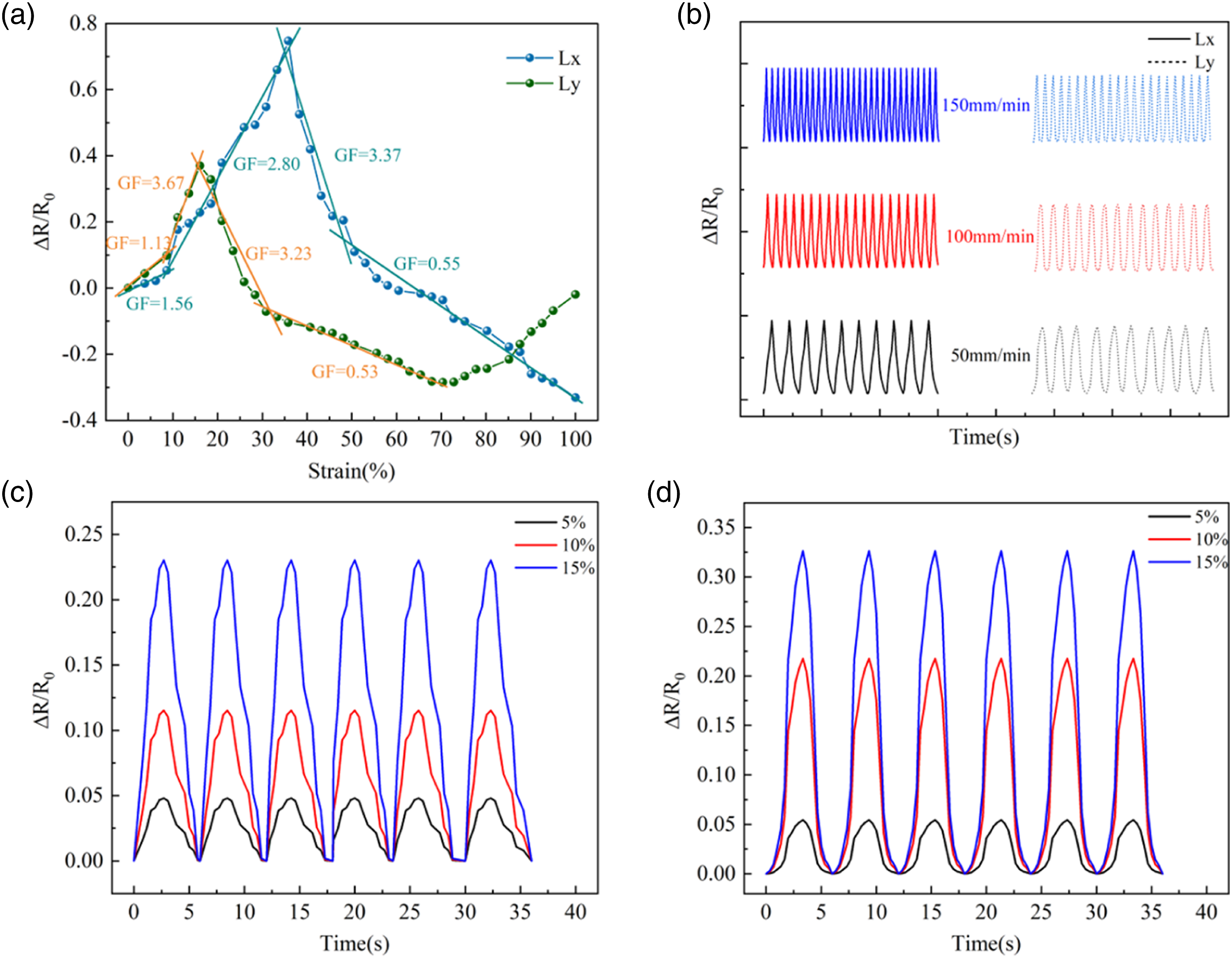
Different strains and stretching speeds
In practice, sensors are subject to dynamic stress as they experience varying speeds and forces from external factors. Therefore, it is crucial to investigate the sensor's properties under different strains and stretching speeds. In this research, strains of 5%, 10%, and 15% were applied to the sensor in the Lx-axis and Ly-axis directions, while the stretching was conducted at a rate of 50 mm/min. The main objective was to examine the dynamic response performance of the sensor, particularly its ability to produce different output curves in response to different strains. The experimental results, as depicted in Figure 8(c)-(d), clearly demonstrate that ΔR/R 0 remains almost consistent for the same strain, gradually increasing with higher applied strains. This observation indicates that the sensor is capable of differentiating between various deformations. Additionally, Figure 8(b) presents the ΔR/R 0 of the sensor at 10% for three stretch rates: 50 mm/min, 100 mm/min, and 150 mm/min. Notably, the height of ΔR/R 0 remains consistent across different rates, implying that the sensing performance of the sensor remains stable regardless of the stretching speed.
Response time
To measure the response time of the sensor, the simulation is conducted. Response time is generally described as the duration needed for a sensor to reach its desired value following a rapid signal stimulation. In this paper, a further stretching test is employed to evaluate the response time of the sensor. For the purpose of rapid stretching, the sensor is maintained at 500 mm/min at 5% strain. Figure 9 depicts the response time of the sensor under the stimulus. Evidently, the response time in the Lx and Ly directions are 300 ms and 450 ms, respectively. It is worth noting that the sensor demonstrates an excellent fast response time. The presence of the tuck loop limits the stretch in the Ly-axis, thereby resulting in a faster response performance in the Lx-axis direction compared to the Ly-axis. Response time of the sensor.
Repeatability
The sensor's repeatability is an important index that characterizes its good dynamic sensing performance, referring to the degree of coincidence of the characteristic curves of the sensor in the same state of repeated testing. To investigate the repeatability of the sensor, 1000 stretch-release cycles at 20% strain were applied to both stretch directions of the sensor. A smaller error in the curve indicates better repeatability in practical applications. From Figure 10(a) and (b), it is observed that the ΔR/R
0
slightly increases with increasing stretch time due to fatigue generated by the fabric. During the release process, the fabric does not fully return to its initial starting position, causing an upward shift in the rate of change of resistance. After 1000 stretch-release cycles, the offset of the transverse resistivity change rate accounted for 5.1% of the original value, while the offset of the longitudinal resistivity accounted for 6.2% of the original value. Overall, the sensor demonstrates good repeatability. 1000 cycles tensile recovery test of resistive sensor (a) Lx axis stretching; (b) Ly axis stretching.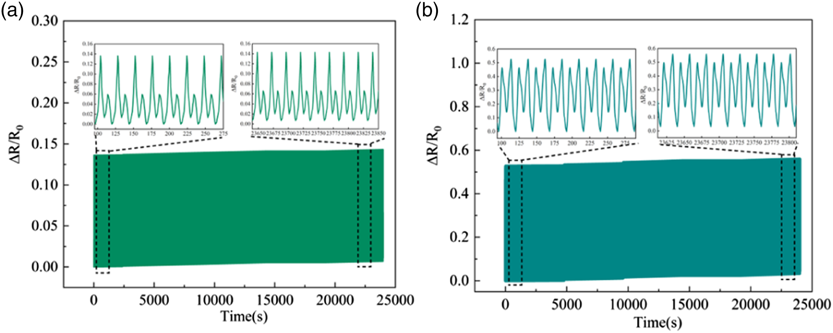
Applications and human motion detection
The designed knitted strain resistance sensor exhibits stable resistive responsiveness under various tensile conditions. It can be immobilized on the volunteer (Female, 162 cm, 50 kg) as a wearable electronic device to monitor human body motion detection. Three types of tubular fabrics prepared by the flat knitting machine—finger sleeves, sleeve sleeves, and knee pads—are expected to monitor the behavioral characteristics of the fingers, elbows, and knees during human activity. To further investigate whether the sensor can monitor continuous body motion behavior, bending behavior was performed on the fingers and elbows, and the change in the value of ΔR/R
0
was recorded simultaneously (Figure 11(a) and (d)). These graphs show that the resistance changes synchronously with the degree of bending when the finger or elbow is bent or extended, indicating the stability of the sensor in terms of limb behavior monitoring. In real-time, the value of ΔR/R0 follows the knee movement as the knee bends back and forth during human walking (Figure 11(b)). Overall, these results demonstrate the excellent performance of the proposed sensor, suggesting potential applications in the field of human body-hugging wearable flexible smart devices in the future. Application of strain sensors in monitoring limb motion (a) elbow bending at different angles; (b) walking; (c) response curves of fingers during different motion phases.
Conclusion
In this work, silver-plated and elastic yarns were introduced into the conductive area of the sensor by the techniques of intarsia and plating. Five types of samples with different content of tuck loops were designed for the conductive region. By exploring their electro-mechanical properties and air permeability and moisture vapor transmission, the optimal one was selected for the final study of the sensor. The combination of knitted loop structure and elastic yarn allows the sensor to reach a 100% stretching range. It also exhibits fast resistance response when stretched in two directions. The sensor exhibited a wider linear operating range in the stretching direction when the amount of tuck loop was 30%. The sensitivity of longitudinal stretch is higher than that of transverse stretch. The GF can reach 2.80 kPa−1 when the Lx-axis strain is 0%–35%, and the GF is 3.67 kPa−1 when the Ly-axis strain at 0%–16%. Moreover, the sensor exhibits good durability and stability within 1000 cycles, resistance differentiation for different rates, and the ability to synchronize between output resistance and input pressure in real-time. The proposed sensor is a flexible fabric that is seamlessly embedded into the clothes and can be directly attached to human skin to monitor human limb motion, such as joint flexion. If the sensors and electronic information technology are combined, it is hoped that the introduction of daily clothing on the human body’s limb movement for truly effective real-time monitoring in the future.
Footnotes
Declaration of conflicting interests
The author(s) declared no potential conflicts of interest with respect to the research, authorship, and/or publication of this article.
Funding
The author(s) disclosed receipt of the following financial support for the research, authorship, and/or publication of this article: This study is supported by National Natural Science Foundation of China (61902150) and Natural Science Foundation of Jiangsu Province (BK20221094).