
Abstract
Two modification methods, including low temperature plasma treatment and HNO3 oxidation, used to modify double-layer knitted fabric (DLKF) with UHMWPE yarn and CFs respectively. Contact angle, Fourier transform infrared spectroscopy (FTIR), Scanning electron microscopy (SEM) are used to evaluate the modification effect of the fabric or CFs. Epoxy resin (ER) is used as adhesive to prepare composite, and the effect of modification on the stab resistance is further studied through the test of stab resistance. In addition, the damage mechanism of DLKF and R-DLKF are analyzed. The results showed that the plasma treatment has a great effect on the modification of DLKF. After 15–20min of modification, the stab resistance of the composite is the best. The peak load and energy can be increased by about 19.1% and 23.1%. HNO3 oxidation has a great effect on the modification of CFs, the stab-resistance of CFs reinforced DLKF (R-DLKF) can be improved by about 17.3% after being treated with 60% HNO3 for 24h. DLKF fails mainly due to the stretching and cutting action of the yarn. Fabric as matrix can prevent crack propagation further, and the shear force, yarn cutting and pullout action within the composite is the key to improve the stab resistance. This work opens up the possibilities for the industrial production of personal protection products and devices, which is expected to provides a reference for the modification of fabrics and fibers in the production of composite.
Keywords
Introduction
Ultra-high molecular weight polyethylene (UHMWPE) fibers and carbon fibers (CFs) have excellent mechanical properties such as high specific strength, specific modulus, low specific density, lightweight, good fatigue resistance, outstanding insulation performance,1–3 etc. Holds a great potential for applications in military, aerospace, transportation, architecture, versatile protection field,4,5 and high-end manufacturing industries,6,7 in these fields, composites are often damaged by puncture of tools, this has caused great losses to people’s lives and economic losses. However, UHMWPE and CFs are chemically inert due to their smooth surface and do not contain hydrophilic groups,8,9 resulting in poor interface adhesion between unmodified fiber and resin matrix. Uneven impregnation of resin in fiber and easy to form voids and defects on the interface, which hinders its application in composites.10,11 From this, the interfacial adhesion behavior between matrix and reinforcement materials directly affects the transmission and dispersion of internal stress.12,13 The interfacial adhesion behavior is related to the interfacial interaction,14,15 it depends not only on the atomic arrangement, molecular conformation and chemical composition of the fiber and matrix, 16 but also on the surface morphology of the fiber and the diffusion ability of the reinforcement, which has a great influence on the mechanical properties of composites.17,18 Therefore, the surface modification of fabric and CFs are very necessary.
Comparison of previous studies.
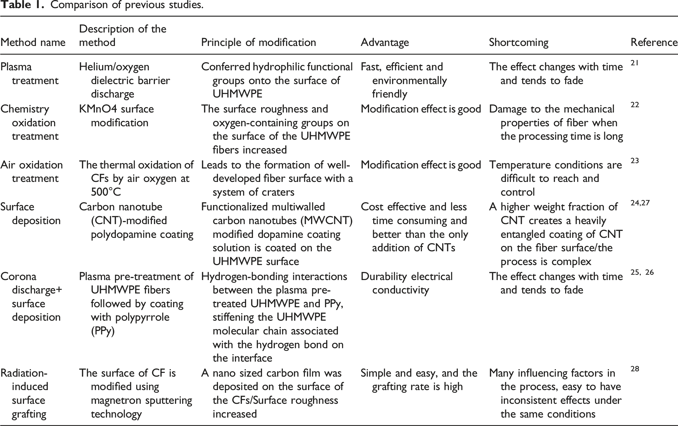
In this work, two modification methods, including low-temperature plasma treatment and 60% HNO3 oxidation treatment, are used to modify the surface of DLKFs and CFs respectively. Stab-resistant composite is prepared based on DLKF. Specifically, the DLKF is knitting using twisted UHMWPE yarn by high-speed fully formed knitting equipment, overcome the difficulty of knitting-high performance yarn, simplified the production process, reduced the production cost. The modification of fabric and CFs greatly promotes the interface bonding ability between the reinforcement and the matrix by improving hydrophilicity and surface roughness, which is also an important reason for the improvement of the stab resistance of the composite. In all, this work presents a simple/effective modification method, which can provide a reference for the industrial production of stab-resistant composites.
Experimental
Materials
In this experiment, DLKFs are fabricated by the weft-knitted machine (Longxing KSC-132, 14 stitches, double-needle bed). The yarn used is UHMWPE, 600D, 80 twist/m, melting point is 130–136°C, (Hangzhou Kezhongyuan Wire Belt Co, Ltd). A polyamide /spandex core-spun yarn 3070 is used for knit together, the addition of elastic yarn is conducive to the shrinkage of the fabric, making the structure more compact. The fabric has a certain thickness, and can be used as an excellent carrier of reinforcing material. The upper and lower layers of the fabric are connected in the form of loops, the warp and weft densities of fabric is about 8.5 loop/cm and 6.5 loop/cm. The structure simulation diagram and process of DLKF are shown in Figures 1(a) and (b). The structure simulation diagram and process of DLKF. (a) Structure simulation diagram of DLKF; (b) process drawing of DLKF.
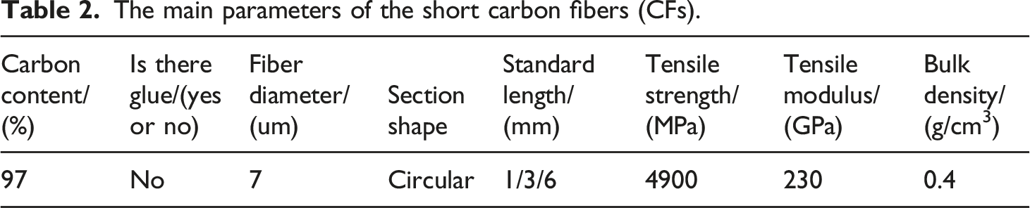
The main parameters of the short carbon fibers (CFs).
Modification of DLKF and CFs
Process of plasma treatment is shown in Figure 2(a) to (d). The low-temperature plasma treatment instrument (SY-DT03S, Suzhou Aopusi Plasma Technology Co, Ltd) is used to modify the surface of the DLKFs.
30
First, O2 is on the left and N2 is on the right in the cylinder cabinet, both gas valves need to be opened. Second, place the fabric in the processing box of the instrument. Third, set the processing parameters, as shown in the Table 3. Then, close and press the cabin door tightly, click the start button, and the instrument starts vacuuming, the gas flows up and down the fabric. After one treatment, turn the fabric over and treat it again, 5 minutes for each treatment. Modification DLKFs and CFs. Plasma treatment instrument of (a) cylinder cabinet and (b) treatment cabinet; (c) principle of plasma treatment; (d) the fabric is placed in the reprocessing cabinet. (e) Oxidation treatment process of short carbon fiber. Parameter of plasma treatment.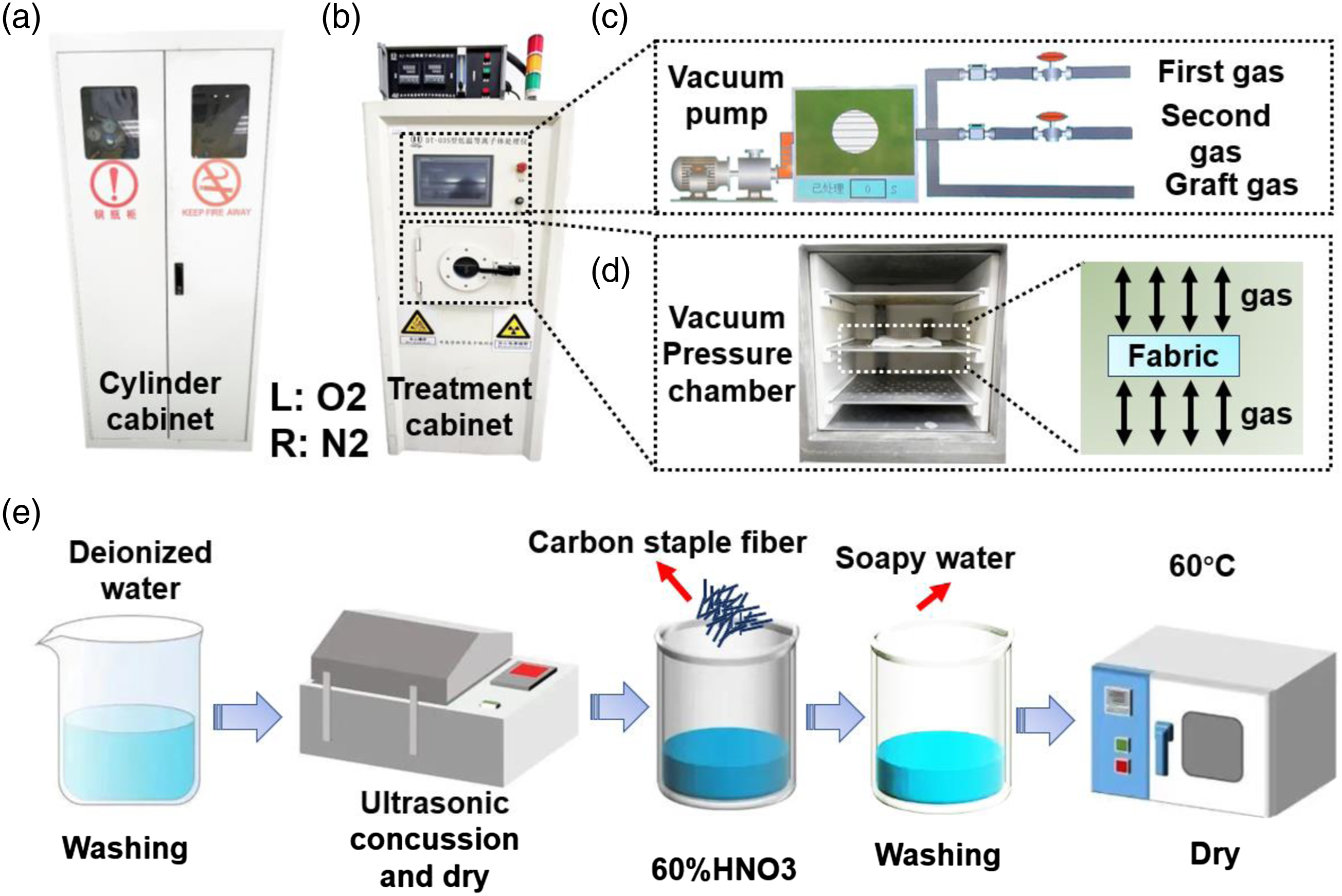

Process of oxidation treatment of CFs is shown in Figure 2(e). Clean the CFs with deionized water and shake them with ultrasonic vibration instrument for 30min to remove impurities on the fiber surface, and then dry it in the oven. The fibers are placed in 60% HNO3, stirred evenly, and treated with 24h/48h/72h respectively. After treatment, the fibers are soaked in alkaline soapy water to neutralize the acid and washed with deionized water for many times, until the foam disappears, and the fibers are dried in oven at 70。C for 6 ∼ 8h.
The preparation of reinforced composites
Using modified DLKF and CFS to preparation reinforced double-layer knitted fabrics (R-DLKFs), ER plays a role in bonding fiber and dispersing CFs. The specific preparation process is as follows: Firstly, the modified fabric is cut to a size of 5x5 cm, weigh and record the weight of each sample. It should be noted that this step needs to be completed within about 5h after the modification, to avoid changes in the fabric surface. Secondly, use silica mold with the same specification, and the mold has a certain thickness, spray release agent in the mold, so the composite can be better removed from the mold. Thirdly, put fabric in mold and quantitatively impregnated with a certain amount of reinforcement, due to the great fluidity of the reinforcement, the coating is uniform. Finally, put the mold into an oven at 60°C, dry for about 2 ∼ 3h and take out.
Characterization of the reinforced composites
The functional group of the DLKF and CFs are characterized by FTIR (Nicolet is 10, Thermo Fisher Scientific). Optical sample images are taken by a digital camera (Nikon DSLR D5100) under ordinary white light. The surface morphologies of the fabric and composite are characterized by scanning electron microscopy (SEM, JSM 7401, JEOL Co Ltd, Japan).
A digital contact angle tester (JC2000DM, Zhong Chen Digital Technology Co, Ltd, China) is used to evaluate the wettability of the fabric samples with a droplet volume of 5 μL.
31
Schematic of setup for contact angle test is shown in Figure 3. The fabric needs to be flat to better observe the hydrophilicity of the fabric. Schematic of setup for contact angle test. (a) Contact angle test details; (b) Contact angle tester.
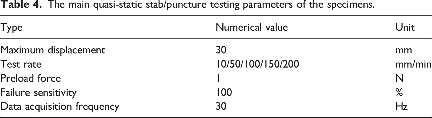
Quasi-static properties can reflect the stab-resistance of materials. Accordingly, displacement-load is recorded, the puncture displacement and load are the maximum displacement and load before puncture, the puncture energy can be obtained by calculating the curve before puncture, the larger the puncture load and energy, the better the stab-resistance.32,33 The quasi-static test equipment is self-designed based on the MTS universal testing machine (MTS Systems (China) Co, Ltd, Shenzhen, China), schematic of setup for quasi-static stab test is shown in Figure 4(a). The fabric and composite are clamped in a ring clamp, the aperture of the ring is 4.5 cm (Figure 4(b)), and a sufficient force is used to clamp the specimen to avoid its slippage. The knife D1 is used (Figures 4(c) and (d)), replace the blade after three tests. The knife penetrated the center of the target at a rate of 10 mm/min, the specific parameters of puncture are shown in Table 4. The length of the blade D1 is 30 mm, so the experimental process of the material within 30 mm is recorded. Some experimental details need to be paid attention to in the experiment, the center position of the materials should be chosen as the puncture points and the deviation of penetration angle of test tool should be less than or equal to 5。. The reference standard for the experiment is the 《Police stab-resistant armor》 (GA 68–2019, China). The standards of composite can be referred to standard 《Test Method for Measuring the Damage Resistance of a Fiber-Reinforced Polymer Matrix Composite to a Drop-Weight Impact Event》 (2015-US-ASTM D7136/D7136M-15). Schematic of setup for quasi-static stab test. (a) MTS puncture instrument; (b) schematic diagram of stab puncture test device and (c) blade; (d) details of the stab blade. The main quasi-static stab/puncture testing parameters of the specimens.
Results and discussion
Parameters of specimens for quasi-static stab/puncture test.

Plasma treatment on stab-resistance of the ER reinforced composite
Plasma treatment is mainly used for fabric surface cleaning, surface activation, surface grafting, surface polymerization, and assisted chemical vapor deposition.34–36 Not only increases the roughness of fiber surface, but also increase hydrophilicity. To determine optimum time of plasma treatment, different plasma treatment times, including 0min, 5min,10min, 15min, 20min, 25min, 30min, are used to comparative experiments. The following results are obtained:
After the plasma treatment is completed, equivalent ER is impregnated. Due to the different modification time, the composite presents different colors after impregnating the resin. The longer the modification time, the darker the color, the greater the oxidation degree, as shown in Figure 5(a). The contact angle of DLKF with different treatment time is tested, the results are shown in Figures 5(b) to (d). When unmodified, the water droplets adhere to the fabric surface, after 148s, the water droplets hardly penetrate the fabric. After modification for 5min, the hydrophilicity of DLKF is effectively improved, after about 2s, the water droplet is completely immersed in the fabric. After 10 min of modification, the hydrophilicity of DLKF is greatly improved, when the water droplets contact the surface of the fabric, they instantly penetrate the fabric. The fabric treated for 15–30min has the similar effect as the fabric treated for 10min, the same contact angle pictures are not shown in this paper. Optical pictures of R-DLKF (ER) and contact angle test results. (a) Optical pictures of R-SLKF (ER) at different plasma treatment times; (b) Contact angle of DLKF before modification; (c) Contact angle of DLKF after modification for 5 min; (d) Contact angle of DLKF after modification for 10 min.
The FTIR result of the DLKF before and after modification is shown in Figure 6(a). Before modification, the fabric is mainly composed of C and H elements, the small wave crest indicates some impurities on the fabric surface. After modification, the main wave crest of the fabric has not changed, indicating that the main components of the fabric are not change, and no O-H groups are formed on the fabric’s surface. However, the small wave crest is disappeared, this shows N2 played a role in cleaning the fabric surface. To explore whether plasma treatment improves the stab-resistance or not, the R-DLKF (ER) is prepared, based on the DLKF before and after modification, the puncture results are shown in Figure 6(b) to (d). After modification of the DLKF,the stab-resistance of the composite has been greatly improved, as shown in Figure 6(b). The puncture load is the maximum force before the fabric is pierced, as shown in Figure 6(c). Compared with unmodified fabric matrix composites (213.15 N), the peak load of modified fabric (15min) matrix composite (253.82 N) increased by about 19.1%. However, the change of puncture displacement of the composite is very small. The energy generated by the composite before being punctured is recorded, from Figure 6(d) that the puncture energy of the modified fabric (20min) matrix composites (1.27 J) has increased by about 23.1% than unmodified fabric matrix composites (1.0 J). To explore whether plasma treatment damage the fabric or not, the stab-resistance of the fabric before and after modification has been tested. As shown in Figure 6(e), the fabric before and after modification has a similar puncture process. From Figure 6(f) that the peak load of the fabric is irregular, after modification for 25min, the peak load is even bigger, this phenomenon may be caused by errors. All in all, this shows plasma treatment has little damage to the DLKF. Plasma treatment results. (a) The FTIR result of the DLKF before and after modification. (b) Stab-resistance of R-SLKF(ER) based on modified fabric and unmodified fabric; (c) peak load of R-DLKF (ER) with different Plasma treatment time; (d) Energy of R-DLKF (ER) with different Plasma treatment time. (e) Stab-resistance of DLKF before and after modification; (f) peak load of R-DLKF(ER) before and after modification. (g) Surface of fabric before modification, and (h) after modification; (i) SEM image of the fabric before modification, and (k) enlarged picture; (j) SEM image of the fabric after modification, and (l) enlarged picture.
The stab-resistance of the R-DLKF (ER) has been improved, it may be that the surface morphology of the fabric has changed. After oxidized by plasma, the fabric feels rough, optical picture of fabric is shown in Figures 6(g) and (h). Under the SEM instrument, the surface of the unmodified fabric is smooth (Figures 6(i) and (k)), and without any damage and groove. However, the surface of the modified fabric (15min) has obvious irregular damage (Figure 6(j), 6L). This shows that the irregular grooves improve the interfacial adhesion between the fabric and ER, so as to improve the stab-resistance of the composite.
The puncture process of DLKF can be divided into five stages, as shown in Figure 7(a). 0∼a, The fabric deforms under stress and absorbs energy quickly, the puncture load gradually increases; a∼b, The blade penetrates the fabric, there is a small fluctuation on the curve. Because DLKF has a double-layer structure, the fabric has not been pierced yet, and the puncture load is still gradually increased. b∼c, The blade tip is stabbed out from the back of the fabric, and the blade tip is locked, becoming a “self-locking effect”
37
; c∼d, The yarn near the blade tip is cut, the fabric broken failure, the puncture load is greatly reduced; d∼e, After the yarn around the knife tip is cut, a new break occurs, and the knife begins to cut the yarn around the circumference again. This phenomenon occurs repeatedly. Since the contact area of the knife blade in the fabric gradually increases, the curve gradually increases in the upward and downward fluctuations. Damage morphology of DLKF shown in Figures 7(b) to (d). Since the blade tip is small, the damage area is small, about 0.5 cm, as shown in Figure 7(b). The surface of the damage area has rough short fibers, as shown in Figure 7(c). It can be seen by observing the fibers at one side of the damage area, the puncture failure of the DLKF is accompanied by fiber cutting and stretching, as shown in Figure 7(d). Puncture process and damage morphology of DLKF. (a) Puncture process of DLKF; (b) Damaged area of DLKF and (c) enlarged image, (d) SEM images from (c).
Oxidation treatment on stab-resistance of CFs reinforced composite
CFs is an inorganic substance with stronger surface inertia. 38 For reinforced composites, the mechanical properties are not only affected by the matrix, but also the interface bonding ability. 39 The experiment is carried out in a vacuum oven with constant temperature of 25°C.
As shown in Figure 8(a), the FTIR result shows that after low-temperature plasma treatment and HNO3 (60%) oxidation treatment, the main elements of CFs do not change. However, the small wave crest is disappeared after modification, this shows that the impurities on the surface of CFs after plasma treatment and oxidation treatment are removed. Use 2.5% modified CFs mixed with ER as reinforcement, and evenly coated on modified DLKFs to prepare CFs reinforced composite. Figure 8(b) shows the stab-resistance of the CFs reinforced composite. Before modification, the bonding ability between CFs and ER is poor, and embrittlement easy occur. The stab-resistance of CFs reinforced composites after oxidation treatment is better than that of after plasma treatment, this shows that low-temperature plasma (389.2 N) modification has little effect on CFs. After HNO3 oxidation for 24h, the stab-resistance of CFs reinforced composite is the best, about 456.7 N (Figure 8(c)). When the oxidation time exceeds 24h, the mechanical properties of CFs are easy to be damaged,22,23 which is not conducive to the stab-resistance of composites. Results of oxidation treatment. (a) The FTIR result of the CFs before and after modification. (b) Stab-resistance of CFs reinforced composite; (c) puncture load of CFs reinforced composite. SEM picture of (d) CFs aggregate before modification, and (g) enlarge picture. SEM picture of (e) CFs aggregate after plasma treatment, and (h) enlarge picture. SEM picture of (f) CFs aggregate after washing and drying, and (i) enlarge picture. SEM picture of CFs after oxygen treatment and treat for (j) 24h (k) 48h (l) 72h.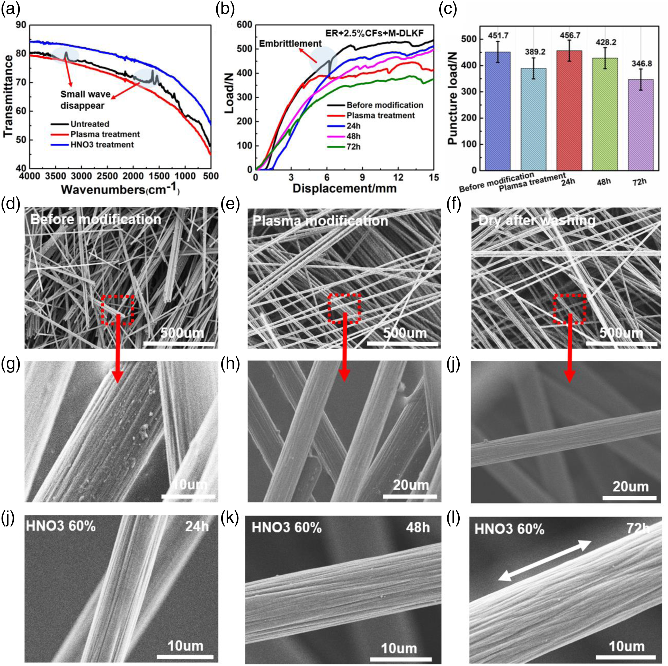
Figures 8(d) and (g) shows the SEM picture of CFs without any treatment, there are obvious impurities on the fiber surface, which will affect the bonding ability between ER and CFs. After plasma treatment or washing, the impurities on the surface are almost completely removed, SEM images of Figure 8(e) to (i) can illustrate this phenomenon. After oxidation treatment of 60% HNO3, the CFs become significantly softer, and the surface of CFs becomes rough, SEM images are shown in Fig. 8(j)∼(l). The surface roughness of CFs is more obvious after oxidation, this shows that the oxidation method has a good effect on the surface modification of the CFs.
Figure 9(a) is optical picture of DLKF treated with ER. The fabric is completely immersed with ER, as shown in Figure 9(b). It shows that the interface between ER and DLKF is good. From Figure 9(c) that there are small particle crystals on the surface of the fabric, this is related to the characteristics of ER material. Figure 9(d) is optical picture of DLKF treated with ER+2.5%CFs. CFs have a certain length, and the clearance of DLKFs is small, which leads to the CFs cannot penetrate the interior of DLKFs, so CFs are evenly covered on the surface of the fabric due to the viscosity of the ER, as shown in Figure 9(e). From the picture the interface between CFs and ER is great. Due to the addition of CFs, the composite surface is very flat, as shown in Figure 9(f). These fibers are amorphous on the surface of the DLKF, the puncture force is well received and dispersed along these amorphous fibers. The cross section of the R-DLKF (ER) and enlarged picture are shown in Figures 9(g) and (h), the R-DLKF (ER+2.5%CFs) and enlarged picture are shown in Figures 9(i) and (j). The combination between fabric and resin is relatively tight, and a single fiber is easily broken. Optical picture and SEM images of reinforced composite. (a) Optical picture of DLKF treated with ER; SEM picture of (b) DLKF treated with ER, and (c) enlarged picture. (d) Optical picture of DLKF treated with ER+2.5% CFs; SEM picture of (e) DLKF treated with ER+2.5% CFs, and (f) enlarged picture. (g) The cross section of the R-DLKF (ER) and (h) enlarged picture. (i) The cross section of the R-DLKF (ER+2.5%CFs) and (j) enlarged picture.
Stab-resistance of CFs reinforced composites
The interface between composites directly affects the direction of stress propagation, and the failure mode of the whole material.40–42 Fabric matrix plays an important role in composite materials.
43
Figure 10(a) shows the stab-resistance of two CFs reinforced composites, one takes the DLKF as the matrix and the other has no fabric matrix. From Figure 10(a) that when the load value of composite with the fabric matrix reaches a certain value, this indicates that the material has a brittle fracture, and the puncture load of this composite is only about 300N. Figure 10(b) shows the brittle fracture of CFs reinforced composites without fabric matrix, this phenomenon greatly reduces the stab-resistance of the composite and limits its application in practice. Photo and SEM images of damaged area for R-DLKFs after quasi-static stab test. Photo images of the damaged area (a) on the front, and (b) back of ER reinforced composite. Photo images of the damage area (c) on the front, and (d) back of the CFs reinforced composite. Optical picture of the damaged area (e) on the front, and (f) back of R-DLKF treated with ER. Optical picture of the damaged area (g) on the front, and (h) on the back of R-DLKF treated with ER reinforced composite. SEM picture of the damaged area of (i) ER reinforced composite, and (k) enlarged picture. SEM picture of the damaged area of (j) CFs reinforced composite, and (l) enlarged picture. Properties of CFs reinforced composites. (a) Stab-resistance of CFs reinforced composites. (b) Brittle fracture of CFs reinforced composites without fabric matrix. (c) Preparation of CFs reinforced composite with fabric matrix; (d)the damage extends in the direction of the fabric coil.

The structure of CFs reinforced composite with fabric matrix is shown in the Figure 10(c). The DLKF has a double-layer structure, and is connected in the way of tuck stitch. One part of ER is immersed in the fabric, the other part is wrapped in CFs, and pasted on the fabric surface together. Fabric plays a role in bearing stress and transmitting stress between fibers, in the puncture process, the force on the material is dispersed by the fabric matrix, and the snared coils of fabric structure (The coils are sleeved with each other, and the single fiber is not easy to be pulled out and broken) enables the composite to be toughened through crack twist bending (The crack propagates along the direction of yarn arrangement, the arrangement of yarns in fabric is twisted and bent) and fiber connection (Connecting coil between upper and lower layers of DLKF), the puncture force propagates along the weaving direction of the yarn, as shown in Figure 10(d). Fabric matrix can prevent brittle fracture phenomenon of composites. Therefore, the stab-resistance of the material is greatly improved under the same conditions.
Puncture process and damage mechanism of R-DLKFs
The puncture progress of R-DLKF is shown in the Figure 11(a) and (b). The two composites have similar puncture curves, but the peak load of R-DLKF(ER+2.5%CFs) is larger. According to the curve, the puncture process can be divided into five stages (Take R-DLKF (ER) as example).44,45 0∼a, The blade starts to contact the surface of the composite, the hardness of the composite surface is large, which can play the role of passivating the blade tip. Due to the rigidity of composite, the blade tip cannot penetrate the composite, so the puncture load gradually increases. a∼b, With the increase of puncture load, the knife begins to penetrate into the R-DLKF, the load immediately decreases to point b by a small margin, which can be attributed to the mechanical response behavior of continuous resistance failure in the interior of the fabric. b∼c, With the increase of puncture force, a new fracture surface is produced, so the load value increases. c∼e, This stage is the repetition of a∼b and b∼c. Puncture process of R-DLKF. (a) Puncture process of R-DLKF(ER); (b) Puncture process of R-DLKF(ER+2.5%CFs); (c) I–X: Optical images of R-DLKF (ER) puncture process; (d) I-VIII: Optical images of R-DLKF (ER+2.5%CFs) puncture process.
The puncture process of R-DLKF is recorded, as shown in Figure 11(c) and (d). There are cracks around the blade tip. In Figure 11(c), (I)∼V corresponding curve 0∼a, at this time, the composite has not been penetrated; V∼VI corresponding curve a∼b, the tip of the knife is exposed from the back of the composite; VI∼VII corresponding curve b∼c, the load continues to increase, but the amplitude is small; VII∼X corresponding curve c∼d, the knife continues downward, and the curve gradually rises in the fluctuation. Similarly, in Figure 11(d), (I)∼IV corresponding curve 0∼a; IV∼V corresponding curve a∼b; V∼VI corresponding curve b∼c; VI∼VIII corresponding curve c∼d.
Figures 12(a) to (d) shows the images of the damaged area on the front, and back of the ER reinforced composite and CFs composite, 1 mm+2.5%CFs+DLKF are observed, the puncture displacement is 30 mm. Figure 12(e) and (h) shows the corresponding optical picture of the damaged area on the front, and back. The damage area of the ER reinforced composite presents a triangular shape, the length is about 1 cm, which is consistent with the shape of the blade D1. The prick on the surface of ER reinforced composite is uniform and flat. In contrast, CFs are pushed out of the CFS reinforced composite surface due to the extrusion of the knife tip. Figure 12(i) and (k) shows the SEM picture of the section damage area for ER reinforced composite. As can be seen from the picture, the UHMWPE yarn is completely covered with ER, UHMWPE cannot move due to the binding effect of ER. Therefore, the damaged area in the middle of the section is neat and consistent. However, at the edge of ER reinforced composite, UHMWPE yarn is pulled out. Figure 12(j) and (l) shows the SEM picture of the section damaged area for CFs reinforced composite. As can be seen from the picture, the damage area of the section is irregular, and shear force and pulling effect mainly exist in the CFs reinforced composite.
In all, when R-DLKF is punctured, the initial crack is transmitted to the adjacent fibers through the matrix, forming stress concentration, resulting in the further fracture of the fibers. With the continuous increase of the broken fibers, the critical clusters are finally formed, resulting in the failure of the composites.
Conclusions
In this paper, low temperature plasma treatment and HNO3 oxidation are used to modification DLKFs and CFs respectively, ER is used as adhesive prepared two kinds of stab-resistant composites, including R-DLKF (ER) and R-DLKF (ER+2.5%CFs). The effect of modification time on the interface of the composite is studied, and characterized by contact angle, FTIR, SEM, and stab resistance of the composite. The puncture process and damage mechanism of DLKF and R-DLKFs are studied too. The following conclusions can be reached: (1) The modification effect of DLKF by plasma is great. After modification, the hydrophilicity of the fabric is greatly improved. FTIR showed that the functional groups on the fabric surface did not change significantly. However, SEM observation showed that the roughness of the fabric surface increased. Through the study on the stab resistance of R-DLKF, it is found that the stab resistance of the composite reached the best after the DLKF treated with low temperature plasma for about 15–20 min. (2) HNO3 oxidation has a good effect on the modification of CFs, irregular grooves are formed on the surfaces of CFs after modification, so as to effectively improve the stab-resistance of R-SLKF (ER+2.5%CFs). The stab-resistance of R-DLKF (ER+2.5%CFs) can be improved by about 17.3% after being treated with 60% HNO3 for 24h. (3) The puncture process of DLKF can be divided into five stages, including deformation, stab into fabric, “self-locking effect”, etc. Yarn stretching and cutting are the principal consideration of fabric broken failure. The puncture process of R-DLKF can also be divided into five stages too, the passivation of the surface to the blade tip, the cutting and stretching of the internal yarn, and the friction between the blade and the composite, are the reasons for the better stab resistance of R-DLKF.
Footnotes
Declaration of conflicting interests
The author(s) declared no potential conflicts of interest with respect to the research, authorship, and/or publication of this article.
Funding
The author(s) disclosed receipt of the following financial support for the research, authorship, and/or publication of this article: The authors acknowledge the financial support from the National Science Funds of China (11972172), the Fundamental Research Funds for the Central Universities (JUSRP22026), and 2020 University Key Platform and Projects in Guangdong Province (2020ZDZX2012).