
Abstract
Disposable face towel derived amorphous carbon prepared by annealing for broad and exacting applications in electromagnetic shielding, electrical heating, etc. This mat with 3D conductive network formed by nonwoven viscose fiber structure gives an outstanding electromagnetic shielding performance of 30 dB and 8161 dB/(g/cm2) at a thickness of 0.168 mm in the frequency range of 0.3–3.0 GHz. In addition, the as prepared mat presents excellent temperature & strain sensing with exceptional sensitivity (BS = 5.5%), and favorable flexibility (1000 bending cycles without fracture). Moreover, the mat provides well Joule heating performance, and the heating temperature can reach over 60°C in 32 seconds under 0.25 A current. More interestingly, the mat shows excellent fire alarm with a fast response (84 ms) and high operating temperature (>500°C). This method provides a simple and low-cost new method for radiation protection, temperature detection, fire alarm and other fields.
Introduction
Wearable smart textiles, strain sensors are widely used in electronic skin1–4 and health monitoring,5–8 and have a broad prospect. But at the same time, the electromagnetic radiation generated by electronic equipment will interfere with human health and instrument accuracy, affecting the normal operation of electronic equipment such as mobile phones, radars and medical instruments. Electromagnetic shielding materials can effectively shield electromagnetic waves through the reflection and absorption of electromagnetic waves. 9 In addition, fast and safe temperature control are highly needed in extreme climates or health testing (fever, neurological disorders, etc.)10–12 and high temperature warning. 12 Therefore, a multifunctional flexible electronic smart textile that integrates strain & temperature sensing, electromagnetic shielding and electric heating performance can be designed to meet the demand.
Generally speaking, there are two ways to obtain textile based electromagnetic shielding materials. One is to prepare functional fibers for weaving, 13 and the resulting fabrics can achieve electromagnetic shielding effect. For example, Zheng Ian Lin 14 and others used polypropylene (PP)/multi-walled carbon nanotube (MWCNT) coated polyethylene terephthalate (PET) yarn to make conductive woven/knitted fabrics. However, the cost of this method is high, and it cannot be popularized on a large scale. Another method is to directly coat traditional textiles. This method is widely used. In previous reports, common coating materials include AgNWs, 15 Mxene 16 and graphene, 17 but this method cannot guarantee the firmness of conductive materials on the surface of fabrics. Therefore, the invention provides a different method to carbonize cellulose nonwovens and realize electromagnetic shielding performance by using the internally formed conductive network. The process is simple and overcomes the above problems.
Cellulose is the most abundant biological material in nature. Cellulose fiber is widely used to prepare sensors. When subjected to simple heat treatment, these cellulose materials can be turned into biomass carbon materials to achieve excellent conductivity, making them suitable for conductive materials used in sensors. Weihong Zhou et al. 18 Prepared a new Fe3O4/cellulose carbide micro nano hybrid microwave absorber with self-assembled porous structure by loading a simple process of hydrolyzing Fe3+ polymer, freeze-drying and annealing. Renewable biomass carbon material has attracted much attention in terms of its rich source, low cost and adjustable structure. Biomass carbon materials such as wood,19,20 bamboo, 21 cotton,22–24 lotus leaf 25 and water chestnut shell 26 have been reported so far. Viscose fiber is a kind of renewable cellulose fiber, with good moisture absorption, softness and smoothness, is widely used in all kinds of textiles, especially through the non-woven technology made of disposable products such as wet towels, face towels, resulting in inevitable waste. Every year, more than 40 million tons of waste textiles are produced all over the world. Therefore, from the perspective of environmental protection and economy, the recycling of textiles has become an urgent problem to be solved. 27 Besides, viscose fiber has good flexibility, ion exchange capacity and biodegradability, and is widely used in textile and chemical industries. 28 Nowadays, most of the research performed on viscose is done by modifying viscose with chemicals, in use of Ag/AgX (X = Cl, I) NPs, 29 alginate,30,31 chitosan 32 and metal nanoparticles. 33 However, to the best of our knowledge, there are few reports on disposable viscose mat by annealing and utilizing up to now, which is of significance for recycling use of textile waste, waste management and circular economy.
Herein, the disposable viscose face towel was carbonized by annealing to form amorphous carbon mat with the concept of green environmental protection. Wherein, the amorphous carbon mat with 3D conductive network endows with outstanding electrical performances, including electrical conductivity of 42 S/m, electromagnetic shielding performance of 30 dB and 8161 dB/(g/cm2), and the heating temperature can reach over 60°C in 32 seconds at 0.25 A current, further showing fast and stable Joule heating performance. In addition, the prepared mats have excellent temperature and strain sensing properties as well as good flexibility. More interestingly, this mat provides excellent fire alarm with a fast response (84 ms) and high operating temperature (>500°C). This carbonized viscose fabric made by simple preparation method has capacity in electromagnetic shielding, electric heating, temperature alarm and so on.
Materials and methods
Preparation of Carbonized face towel
Disposable face towel (JM102, 20×20 cm, 230 g) was purchased from Zhejiang Keer Cosmetics Co., LTD, China. The preparation process of carbonized viscose fabric is shown in Figure 1. First, put the dried sample into the tubular furnace (OTF-1200X). In order to compare the performance of the sample under different carbonization temperatures, raise the temperature to 300°C, 600°C and 900°C respectively under the protection of nitrogen, annealing at the heating rate of 5°C/min, N2 inlet rate of 2.5 ml/min, carbonize at the corresponding temperature for 2 h, and cool at room temperature. The prepared samples were named CVM-300, CVM-600 and CVM-900, respectively. To compare the samples before and after carbonization, the original disposable face towel without carbonization was named CVM-0. Preparation process of CVM fabric and application in electromagnetic shielding, piezoresistive strain and electric heating.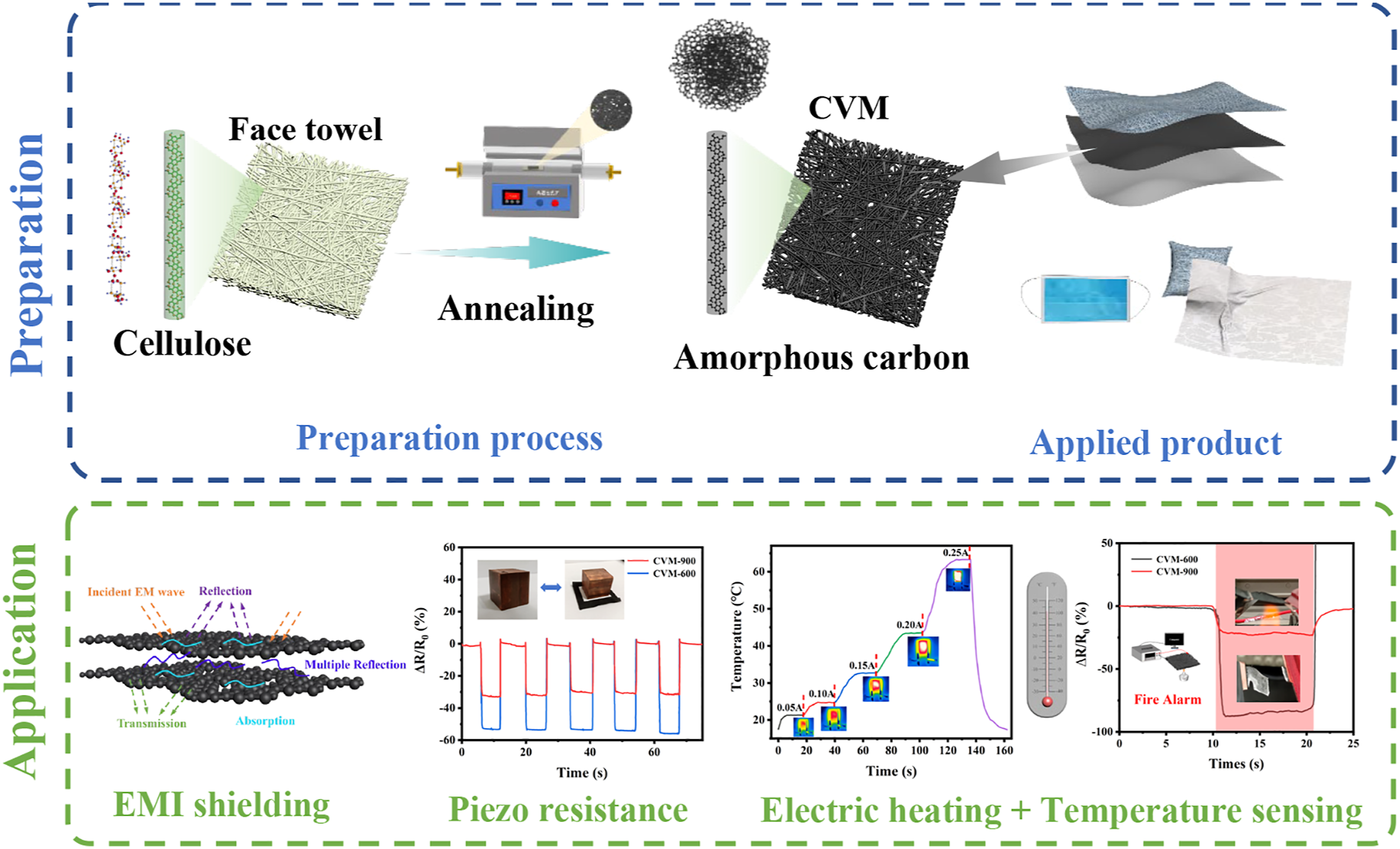
Characterization
The morphology of the carbonized viscose fabrics was characterized using a scanning electron microscope (SEM, Sigma 300, Zeiss, Germany); the functional group of material was analyzed by a Fourier infrared spectroscopy (FT-IR, Nicolet Fourier infrared spectrometer, Thermoelectric Negoly Company) in the spectral range of 500–4000 cm−1; the X-ray photoelectron spectraof the samples were obtained using an X-ray photoelectron spectrometer (XPS, K-alpha, Thermo Scientific, USA); the resistance of the samples was measured using a resistance tester (DMM 6500. Tektronix Co, Ltd., China). The electromagnetic shielding effectiveness of the samples was measured by a fabric anti-electromagnetic radiation performance tester (EMI SE, FY800, Wenzhou Fangyuan Instrument Co., Ltd, China); a self-assembled dynamic resistance tester was used to record the resistance changes of the samples under different strains, including resistance tester (DMM 6500. Tektronix Co, Ltd., China) and mechanical test system (EJA SERIES, Thwing-Albert Co., USA); an infrared thermal imaging camera (InfraTec, FLIR System, Germany) was used to record the temperature distribution and thermal images of the samples, and the applied constant current was provided by a three-way programmable DC power supply (IT6322, ITech, USA).
Result and discussion
Figure 2 shows the basic morphology, composition and structure of the carbonized viscose at different carbonization temperatures. As Figures 2(a)-(d) shown, the impurities and grooves on the fiber tow surface gradually decrease with the increase of carbonization temperature and the micro voids can be observed on the surface of single CVM-900 fiber. Figure 2(e) shows the infrared spectra of CVM-0, CVM-300, CVM-600 and CVM-900, the absorption peaks at 3351 cm−1 (corresponding to hydroxyl group of -OH) and 995 cm−1 (corresponding to -CH) gradually decrease with the increase of temperature. Which is mainly ascribed to that the carbonization process of cellulose viscose fiber is a pyrolysis process,
34
with the increase of carbonization temperature, the hydroxyl group (-OH) in the viscose is destroyed and gradually change to carbon mat structure, while the decrease of R1CH=CH2 was due to the small amount of olefins contained in the production of disposable washcloths during the carbonization process gradually volatilized with the increase of carbonization temperature. The polar functional groups that may be contained in disposable face towels have been removed during the carbonization process, and they are chemically inert and harmless to human body. Moreover, carbonated CVM-900 has good air permeability and will not affect its function as an intelligent wear-resistant textile (Figure 2(i)). The XPS spectra of the carbonized samples are shown in Figure 2(f), where the C1s and O1s peaks can be observed at 284 eV and 533 eV, respectively. The C1s and O1s XPS spectra of the carbonized samples were peak fitted and the results are shown in Figures 3(g) and (h). The C1s spectra of the three fabric samples can be fitted by three sub-peaks of C-C, C-O and O=C-O bonds with centers of 284.7 eV, 286.5 eV and 288.2 eV, respectively.
35
The O1s spectrum can be fitted by one peak of the C-O-H bond, centered at 532.6 eV, indicating that as the carbonization temperature increases, the C=O, hydroxyl and hydrogen bonds in the cellulose molecule are destroyed,
36
water molecules and CO2 are precipitated, and the graphitization of the fabric is increased. To sum up, the increased graphitization incorporates into nonwoven network structure provides a 3D conductive network of the internal electron transfer, which improves the electromagnetic shielding, electrical heating, and fire alarm properties of CVM. SEM images of (a) Pristine、(b) CVM-300、(c) CVM-600 and (d) CVM-900. (e) FTIR spectra of Pristine、CVM-300、CVM-600 and CVM-900. (f)-(h) XPS spectra, C1s spectra and O1s spectra of CVM-300、CVM-600 and CVM-900. (i) Permeability test of CVM-900. (a) Electromagnetic shielding mechanism diagram. (b) Electromagnetic shielding effectiveness of Pristine, CVM-300, CVM-600 and CVM-900. (c) EM shielding effectiveness of CVM-900 with different layers. Plots of (d) thickness/SE versus thickness and (e) grammage/SE versus grammage for CVM-900 (curve is a linear fit). (f) X-band electromagnetic shielding radar maps of Pristine, CVM-300, CVM-600, and CVM-900. (g) Radar plots of X band electromagnetic shielding for CVM-900 at different layers.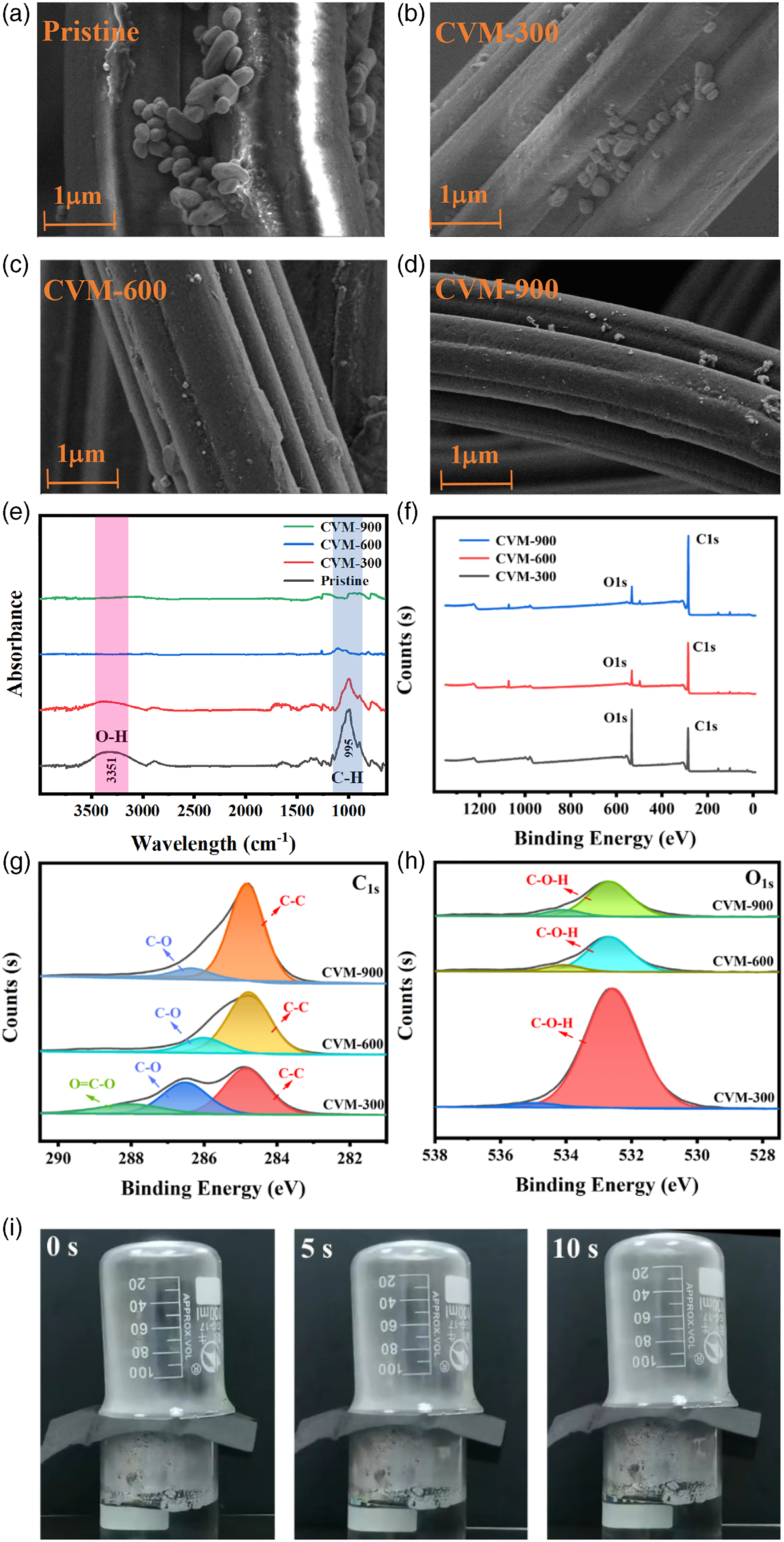

Figure 3(a) shows the electromagnetic shielding mechanism of carbonized viscose. When the incident electromagnetic wave collides with the carbonized viscose surface, the movable carriers on the material surface interact with the incident electromagnetic wave, so that part of the incident electromagnetic wave will be reflected. When the remaining electromagnetic wave propagates into the sample, part of the electromagnetic wave will be absorbed due to ohmic loss and polarization loss. Also, the porous structure of the nonwoven material, repeated reflections and scattering further lead to absorption of electromagnetic waves, so that only a small fraction of the electromagnetic waves pass through the fabric. 37
Figure 3(b) shows the electromagnetic shielding efficiency (SE) of three samples with different carbonization degrees. The electromagnetic shielding ability of CVM-300 and CVM-600 remains unchanged, basically the same as CVM-0, while the electromagnetic shielding ability of CVM-900 is significantly improved up to 30 dB. This is mainly as ascribed to that in the early stage of carbonization, the pyrolysis of cellulose is mainly controlled by dehydration and depolymerization. After carbonization, the cellulose presents a porous structure, which is evenly distributed in the whole sample. Many carbon nanofibers are wrapped around the mesopores, which can provide electron transfer paths and form conductive networks, significantly improving the conductivity of carbon electrodes. At 600°C, the cellulose bundles still maintain a fairly crystalline structure. With the increase of temperature, this crystal shows signs of instability, because some cellulose chains are misplaced from their original positions, and the further increase of temperature leads to the gradual decomposition of fiber bundles. At 900°C, the main part of the beam has been depolymerized into various types of segments, so the electromagnetic shielding at 600°C is quite different from that at 900°C. 38
As shown in Figure 3(c), the SE of CVM-900 becomes stronger when the number of sample layers increases. When the CVM-900 is four layers, the thickness is 0.672 mm, the electromagnetic shielding efficiency can reach 52 dB, and the minimum is 37 dB, is three layers, the thickness is 0.507 mm, the minimum electromagnetic shielding efficiency is 33 dB, meeting the industrial electromagnetic shielding fabric and microwave radiation anti-chemical suit class B standard based on standard of GB/T 23463-2009.
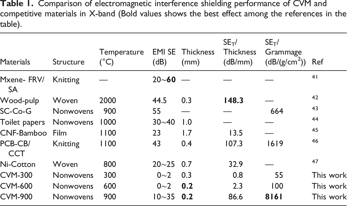
Comparison of electromagnetic interference shielding performance of CVM and competitive materials in X-band (Bold values shows the best effect among the references in the table).
Figures 3(d)-(e) shows the linear relationship between thickness/SE vs. thickness, grammage/SE vs. grammage for CVM-900. The reciprocal of the slope gives values of SE, namely 71 dB and 60 dB. The main mechanism is that the electromagnetic shielding does not reach saturation reflection when the thickness and grammage of the prepared carbonized viscose is low mass and low bulk density. Overall, the linear trend of grammage/SE vs. grammage of the carbonized material is obvious. This trend means that a smaller amount of CVM makes more efficient in providing shield of the microwave.
The EMI SE of material is closely related to the thickness and grammage of the sample. To study the influence of sample thickness on the electromagnetic shielding performance, CVM-900 was stacked together for electromagnetic shielding test. Figure 3(f) provides the SE, SE/thickness and SE/grammage of the CVM under different temperatures, and Figure 3(g) shows the radar plots of SE, SE/thickness and SE/grammage of CVM-900 at different layers in X-band. The EMI SE increases from 0.45 dB to 17.14 dB with the annealing temperature increases from 300°C to 900°C, which is caused by the degree of carbonization of the viscose. And EMI SE increases from 17.1 dB to 37.8 dB with the increase of thickness. Obviously, SE/grammage increases with the increase of carbonization temperature and thickness, from 55 dB/(g/cm2) (300°C, 0.266 mm) to 8161 dB/(g/cm2) (900°C, 0.168 mm), mainly owing to mass and thickness are the main factors that determine the electromagnetic shielding performance of the material within skin depth.39,40
Figures 4(b)-(c) shows the ΔR/R0 curves of the CVM-600 and CVM-900 fabric sensors response to different pressure actions. The strain of the fabric is generally sensed by the change in resistance ΔR/R0 in response to the strain. The relative resistance change of CVM-600 under the same pressure is larger than that of CVM-900, indicating that the contact resistance of CVM-600 plays a greater role than that of CVM-900. And the relative resistance change of CVM fabric sensor increases with the increase of pressure. (a) Schematic diagram of the bending sensing test system. (b–c) Response curves of ΔR/R0 under different pressures for CVM-600, CVM-900 fabric sensors. Durability of (d) CVM-600, (e) CVM-900 fabric sensor for 100 and 1000 bending cycles. (f) Schematic diagram of the electrical contact of the fabric sensor under bending and releasing. (g) ΔR/R0 of CVM-600 and CVM-900 after 1000 bending cycles.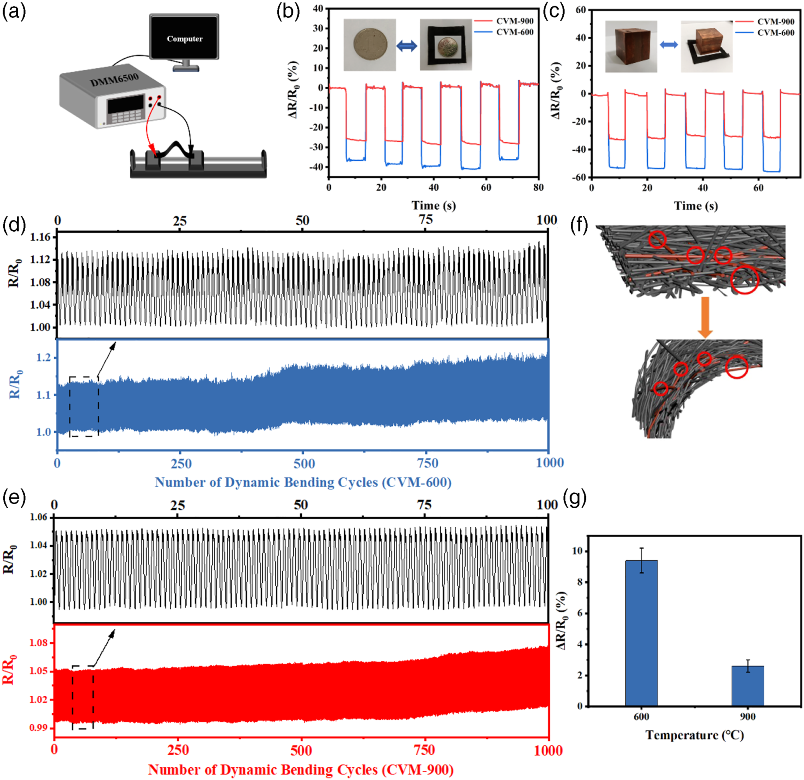
Figure 4(d)-(e) shows the resistance changes of CVM-600 and CVM-900 fabric sensors for 100 and 1000 bending cycles, with the increase of dynamic bending cycles, the resistivity tends to increase, where the fluctuation of CVM-600 is larger. In order to express the sensitivity of bending sensing, BS (bending sensitivity) is defined. This value represents the change of resistance per unit bending angle, so the greater the value, the higher the sensitivity. The calculation formula is defined in equation (1):
From the figure, it can be calculated that the BS value of CVM-900 is 5.5%. The relatively low sensitivity of CVM-900 is ascribed to the fast recovery of 3D conductive network contact points. Therefore, the sensitivity of CVM-900 is lower than that of prior works.48,49 The relative resistance change of CVM-900 is smaller than that of CVM-600 (shown in Figure 4(g)), which is only 2.6% and has better stability.
Figure 4(f) is a schematic diagram of the principle of resistance change of the fabric sensor under bending and releasing. When the fabric is bent, the contact points between the fibers become less, and the corresponding fabric resistance increases. As the bending cycles increases, few permanent displacements or damage has occurred in nonwoven fabric, leading to an increase in its resistance compared with the initial state. These results vividly illustrate the better durability of the carbonized viscose material and expect more stable performance in future studies.
Figure 5(a)-(b) shows the change of CVM-600 and CVM-900 resistance with data acquisition frequency. According to Formula 1, when the data acquisition frequency is 0.02s, the BS values of CVM-900 and CVM-600 are 5.5% and 14.3% respectively, and when the data acquisition frequency is 0.68s, the BS values of cvm-900 and cvm-600 are 4.4% and 6.2% respectively. When the acquisition frequency decreases, the corresponding sensitivity of the sensor will also decrease, which indicates that the data acquisition frequency has a negative effect on ΔR/R0 has a great impact on the results. Which may lead to errors during experimental analysis, so the selection of data acquisition frequency is important for the sensitivity, gauge factor (GF), and response time of the sensor. Figure 5(c) shows the correspondence between the fabric ΔR/R0, the deformation, and deformation speed in the cyclic process, which can be divided into four stages. (i) Sample bending deformation and bending speed gradually accelerated, at the same time, the fiber began to slip between the contact points become less, the resistance began to rise. (ii) Bending speed gradually decreases until it stops, the fiber bending deformation to the maximum, the contact point begins to slip, the resistance gradually increases and returns to a small section. (iii) Bending deformation began to recover and gradually accelerate, the contact point decreases, the resistance increases slightly. (iv) Bending deformation is completely restored, the contact point continues to return, and the resistance decreases sharply. In summary, the resistance change of the textile sensor mainly occurs to the beginning and end of the deformation, mainly related to the structure of the sensor and deformation. Schematic diagram of (a) CVM-600, (b) CVM-900 resistance vary with the data acquisition interval, indicating the influence of data acquisition frequency on the ΔR/R0 plots. (c) Schematic diagram of corresponding relationship between ΔR/R0, deformation and deformation speed during bending cycle.
Figure 6(a) shows the schematic diagram of the electrothermal test setup, and Figure 6(b) is thermal imaging of CVM-900, indicating that the CVM-900 converts electrical energy into thermal energy at the applied current, showing a relatively uniform temperature distribution image. Figure 6(c) represents the equilibrium temperatures of the CVM-900 are 21.3°C, 24.8°C, 32.8°C, 47.2°C and 64.6°C at different constant currents of 0.05 A, 0.10 A, 0.15 A, 0.20 A and 0.25 A, respectively, and the temperature rise rate of the CVM-900 is stable at about 3 s in low current and at about 32 s in high current.
50
As Figure 6(d) shown, the applied current increases from 0.05 A to 0.25 A, the which results in relative resistance ΔR/R0 of CVM-900 changes from −1.14% to −6.16%. After turning off the constant current, the relative resistance of the material return to the initial state. Figure 6(e) shows the temperature variation of CVM-900 within 4 min under different currents, indicating the well electrical heating stability. Figure 6(f) shows successive temperature evolution of CVM-900 under different currents. The steady-state temperature of CVM-900 under different currents is shown in Figure 6(g), and the equilibrium temperature is roughly linear with the square of the current. (a) Schematic diagram of the electrothermal testing setup for CVM. (b) Thermal imaging of CVM-900 under heating-cooling cycle. (c) Real-time temperature of CVM-900 under different currents. (d) Relative resistance of CVM-900 versus time under different currents. (e) Long time temperature variation of CVM-900 under different currents. (f) Successive temperature evolution of CVM-900 under different currents. (g) Plot of steady-state temperature of CVM-900 at different currents. (h) The 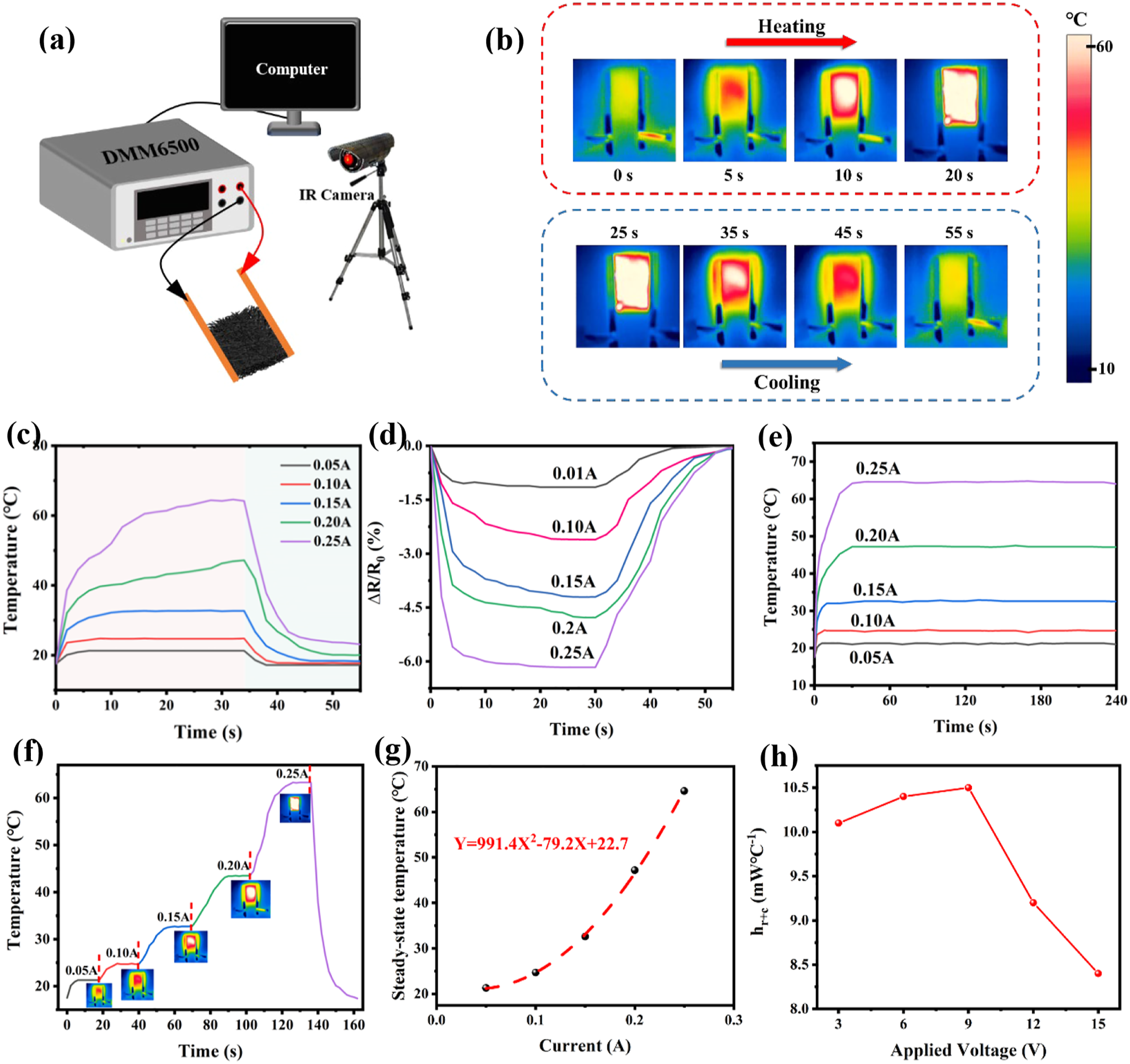
Since electric energy cannot be completely converted into heat energy in the process of electric heating, under the action of applied voltage, the steady-state maximum temperature of carbon felt remains unchanged. According to the law of conservation of energy, the thermal gain of electric power is equal to the heat loss of radiation and convection
51
, 
Figure 7 shows the temperature sensing performance of CVM fabric. As Figure 7(a) shown, when molecular thermal motion increases, the average speed of microscopic particle accelerates, followed by the external bound electrons transfer into free electrons, resulting in resistance decreases with the temperature increasing.
38
Figure 7(b) shows that the relative resistance of CVM-900 changes linearly with oven temperature, and its resistance temperature coefficient is −0.665%/°C, also indicating that the resistance change of CVM-900 is caused by temperature change. (a) Schematic illustration of CVM fabric temperature sensing. (b) Plot of the relative resistance of CVM-900 vs. oven temperature. (c) Curves of temperature vs. time (in blue) and corresponding ΔR/R0 vs. time (in red) and for CVM-900 at 0.25 A. (d) Plots of ΔR/R0 of CVM-600 (in black) and CVM-900 (in red) for fire alarm. The red color area indicates the change of relative resistance of the fabric under burning. (e) Plots of ΔR/R0 under fire alarm cycles for CVM-900, the flame contact zone is marked in red, and the flame removal zone is marked in blue. The responding time of ΔR/R0 to the flame are suspended.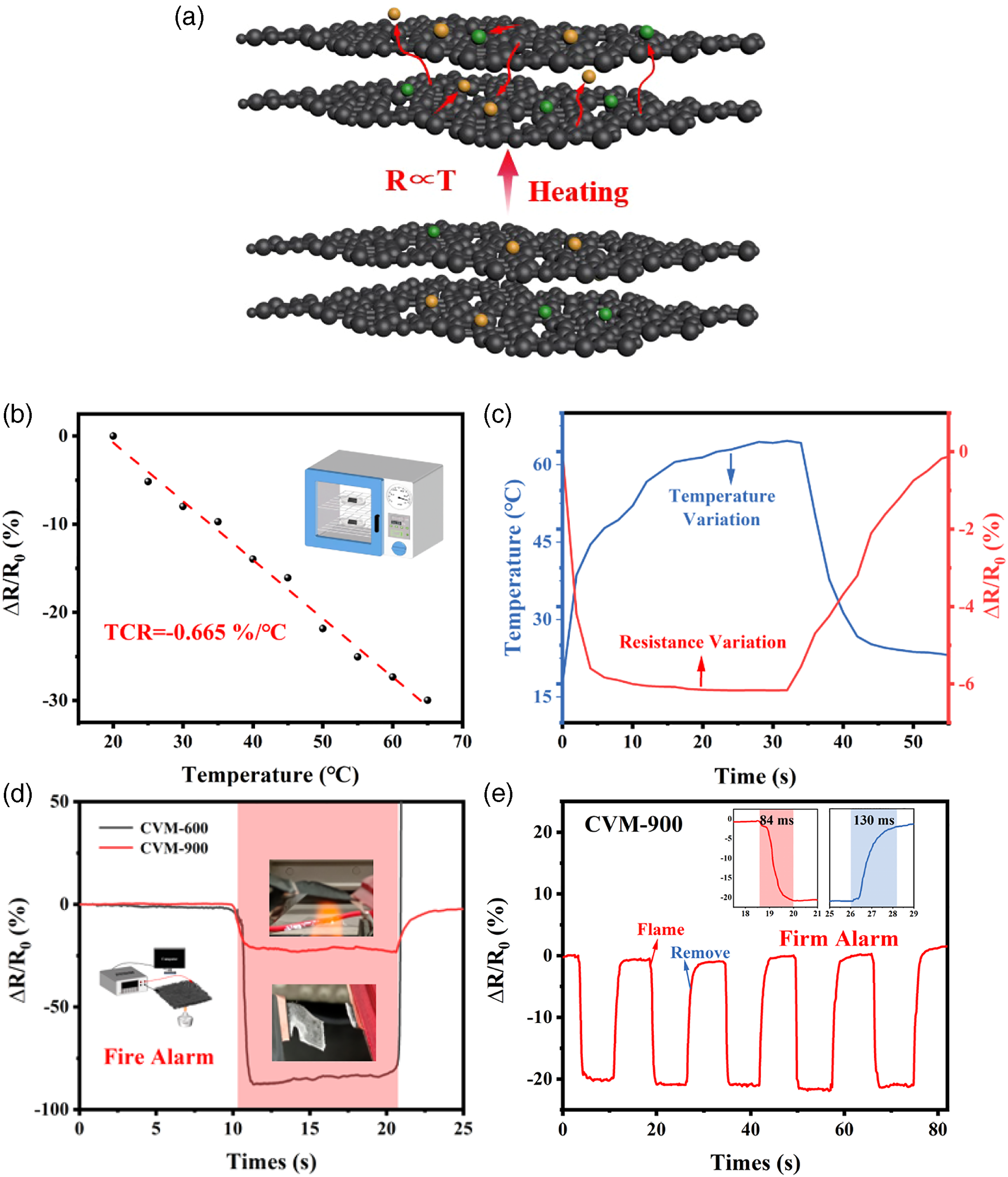
Figure 7(c) shows the curves of temperature and corresponding ΔR/R0 vs. time for CVM-900 at 0.25 A. The fire alarm can be achieved based on the change of the relative resistance of CVM-600 and CVM-900 fabrics as Figure 7(d) shown. The red color area indicates that the relative resistance of the fabric employed obvious variations of −90% (CVM-600) and −20% (CVM-900) within 79 ms and 84 ms when the flame operates to contact CVM, they have short response time and high sensitivity. This is due to the fact that flames are electrically conductive plasma. Therefore, the conductivity of the sample is instantly improved. After the flame move out, the CVM-600 breaks and the resistance rises to infinite immediately. More interestingly, the CVM-900 was completely carbonized and did not burn, when the flame left, the resistance returned to the original state in 103 ms, indicating the capability of multiple reuses. In sum up, CVM-600 and CVM-900 can be used for fire alarm, and CVM-900 can be reused to reduce the cost. Figure 7(e) shows the repeatability and stability of CVM-900 for fire alarm. When CVM-900 is placed on the alcohol lamp, its resistance will immediately decrease by to 20%, and the resistance will recover after the flame leaves. After repeated several times, it is found that the resistance change is basically stable, indicating this CVM can be recycled for fire alarm as an easily prepared, cost-effective and valuable material.
Figure 8(a) is the schematic diagram for measuring resistance of different lengths of CVM. Figure 8(b) shows the equivalent circuit model of CVM, which is used to decouple the contact resistance Ri. Wherein, the contact interface resistance is Ri, CVM self-body resistance is Ra, and gap resistance is Rb.
35
CVM in the circuit is in parallel with the air in the pores between the internal fibers, which is then connected in series with two electrical contacts. In order to explore the interface effect of CVM, resistance values of different lengths were tested, the results are shown in Figures 8(c)-(d). The resistance gives a linear relationship with thickness. Based on the equivalent circuit model (Figure 8(b)) and fitting results, the self-body conductivity and contact interfaces resistance Ri (half intercept) between CVM and copper electrode can be extracted. The self-body conductivity is 3×10⁻⁴ MΩ and 42 Ω respectively. The resistance of CVM in contact with copper electrode at 600°C and 900°C is 8.5 MΩ and 17 Ω respectively (Figure 8(f)), indicating that the contact resistance between copper electrode and CVM is remarkable in terms of self-body resistance of the material body. The contact resistance Ri has significant influence on the characterization and application of electrical characteristics such as electric heating. (a) Schematic diagram of resistance measurement of CVM in-plane direction. (b) Equivalent circuit model of the CVM. (c) Plot of resistance vs. thickness for CVM-600 and (d) CVM-900. A schematic diagram of the resistance R versus thickness d used to determine the contact resistance Ri of the specimen is placed internally. (e) Electrical conductivity of CVM-600, CVM-900 in plane direction. (f) Contact resistance Ri of CVM-600 and CVM-900.
Conclusions
To sum up, we developed a disposable face towel derived CVM, which is prepared by a simple annealing method. Suitable carbonization temperature gives the CVM well electromagnetic shielding performance (30 dB and 8161 dB/(g/cm2)), electric heating performance (can heat up exceed 60°C within 32 s under a low current of 0.25 A), strain and temperature sensing (TCR = −0.665%/°C). In addition, the CVM can be used for fire warning, where the carbonized CVM can detect the flame within 84 ms based on variation of resistance, and capable of reusability, costless and easily prepared. Therefore, this work provides a new idea and method in use of disposable face towel derived carbonized viscose mat for fabric heater, electromagnetic shielding, strain and temperature sensor, flame alarm and other technologies.
Footnotes
Declaration of Conflicting Interests
The author(s) declared no potential conflicts of interest with respect to the research, authorship, and/or publication of this article.
Funding
The author(s) disclosed receipt of the following financial support for the research, authorship, and/or publication of this article: This research was supported by the Public Welfare Project of Zhejiang Province (LGF21E030005), China Postdoctoral Science Foundation (2022T150581, 2020M681917), National Natural Science Foundation of China (NSFC 51803185).