
Abstract
In this study, the effects of both D-lactide content, that is, the change in PLA crystallizability, and molecular weight of polylactide (PLA) on its electrospinning behavior, along with thermal and mechanical properties of the electrospun mats were investigated. Although the effect of D-lactide content on processability of PLA has been studied in extrusion, thermoforming, foaming, and melt spinning, it has not been explored in electrospinning. The current study aimed to analyze electrospinnability of three different PLA grades; two amorphous with high and low molecular weights (i.e., aPLA-H and aPLA-L) and a semicrystalline with a high molecular weight (cPLA-H). PLAs were dissolved at different concentrations in chloroform (CHL)/dimethylformamide (DMF) at various volume ratios. Due to its high crystallizability and molecular weight, coarser nanofibers of cPLA-H were produced from solvents with high CHL content (≥75%), resulting in highest water vapor transmission rate (50,000 g/m2.day) of mats. aPLA-H revealed coarser nanofibers than that of aPLA-L due to its higher molecular entanglement. Although the increase in DMF content in the solvent hindered dissolving and electrospinning of cPLA-H, it caused the refinement of nanofibers in amorphous PLAs. Despite similar tensile strength, cPLA-H showed higher elongation at break (∼69%) than that of aPLA-H (∼59%) possibly due to the existence of some beads within the fibers in aPLA-H. Storage modulus of electrospun cPLA-H was also higher (∼15MPa) than that of other samples (∼10–12 MPa) due to high content of crystallinity (∼37%) while aPLA-L revealed the lowest storage modulus (∼10MPa) due to its amorphous structure and low molecular entanglement.
Introduction
The need of using sustainable and biobased polymers increases globally due to environmental concerns. PLA is a biodegradable and biocompatible aliphatic polyester, which is derived from renewable resources, thus, a good candidate for replacing petroleum-based polymers and decreasing carbon emission.1,2 PLA and its compounds can be used in wide commodity and engineering applications due to its good mechanical, physical, and thermal properties.3–6 In this context, PLA could also be employed for the production of nanofibers through electrospinning process with the potential use in the fields of tissue engineering,7–11 drug delivery,12–15 pH indicator,16,17 filtration,18,19 separation,20,21 sensor application, 22 and food packaging.23,24
Electrospun nanofibers, having significant properties such as a very high surface area to volume ratio,25,26 high porosity27,28 and small pore size,29,30 are produced by employing electrostatic forces. A polymer solution is fed to the syringe pump and then get electrically charged by applying an electric field between the metal tip of the needle and the collector.31,32 When the voltage exceeds a critical value, an electrically charged jet ejects from the tip of the needle and travels to the surface of the collector.33–35 During this motion, the polymer jet stretches and gets thinner forming fibers, the solvent evaporates, and the fibers would be spread onto the collector.36–40 The properties of nanofibers strongly depend on the parameters during electrospinning, which can be categorized into three groups: process parameters, solution parameters, and ambient parameters.20,40
Existing studies have mainly focused on the production parameters and the end-use performance of the electrospun PLA nanofibers. Selatile et al. 41 investigated the effects of solvent type, polymer concentration, voltage, and feed rate on fiber diameter; and the structural properties of nanofibers on the mechanical performance of the electrospun mats. Casasola et al. 42 conducted a comprehensive study on electrospinnability of PLA using seven different solvents [i.e., acetone (AC), 1,4-dioxane (DX), Tetrahydrofuran (THF), dichloromethane (DCM), CHL, DMF, and dimethylacetamide (DMAc)]; however, only AC produced decent electrospun fibers due to high dielectric constant and conductivity of AC and low surface tension of the solution. PLA nanofibers with specific surface or internal features, such as nano-pores on their surface, and porous or hollow interiors were produced by controlling production parameters such as voltage, feed rate, and needle-to-collector distance, environmental parameters such as temperature and humidity, and choosing appropriate solvent and non-solvent systems.20,43 To control the pore size of the electrospun mats and improve their mechanical properties, Li et al. 18 applied a post-treatment technique of annealing on the electrospun mats. They reported the effect of annealing on membrane structure, porosity, hydrophobicity, and mechanical properties. Post-treatment with ethanol was also applied to PLA electrospun mats by Pavlova et al. 11 to analyze the changes in structure and mechanical properties.
The molecular structure of PLA such as its molecular weight and D-lactide content could significantly influence the fiber formation and the properties of electrospun nanofibers. However, only the effect of molecular weight of PLA on its electrospinnability has been explored in few studies.44–46 However, in these studies, the direct effect of molecular weight has not properly been disclosed since each PLA with different molecular weight have been either incorporated at different concentrations or the crystallization differences of the PLAs could have also influenced the electrospinning behavior of the fibers. The findings of these studies are as follows: Li et al. 46 reported that uniform nanofibers could be produced from high molecular weight (503 kg/mol) PLA solutions even with a concentration of 0.5% w/v, which was below the corresponding entanglement concentration (1% w/v). It was concluded that the molecular weight was a critical factor for producing uniform PLA fibers rather than the entanglement concentration. In another study, 44 two different molecular weights of PLA were used, and it was found that at lower viscosities, beads were formed due to the surface tension being the dominant factor. They also showed that with increasing solution concentration, the fiber diameter increased. In addition, the average fiber diameter produced from the low molecular weight PLA at 9 wt. % was around 400 nm; however, high molecular weight PLA produced fibers with a similar diameter at 4.5 wt. %. Although the solution concentration was lower for the high molecular weight PLA, it formed enough entanglements to create a sufficient level of viscosity for restraining the effect of surface tension and producing fibers with uniform morphology.
Commercial PLAs are copolymers of poly(L-lactide) (PLLA) and poly(DL-lactide) (PDLLA) based on L-lactide and DL-lactide dimers, respectively, in which the molecules are rich in L-monomers, and contain D-monomers as co-monomers.1,3 Molecular configuration and the D-lactide co-monomer content in PLA molecules could be another determinative parameter on the formation of electrospun fibers. While PLA inherently possesses a slow crystallization, the change in D-lactide content could significantly influence its crystallizability.47–49 It has been reported that the PLA with D-lactide content beyond 8 mol% appears as a fully amorphous material without any crystallization-ability even after long annealing processes. When the D-lactide content is below 2 mol%, the crystallizability of PLA increases dramatically, and PLA products with certain contents of crystallinity could be manufactured.1,6,50
The effect of D-lactide content on the characteristics of PLA foams,51,52 extruded PLA films, 53 injection molded and annealed PLA films 47 and melt spun PLA fibers 54 was previously studied. On the other hand, in only one study, 55 PLA grades with slightly different D-lactide content (4.2 wt% and 2.0 wt%) were employed to produce electrospun scaffolds loaded with different drugs. In this study, the change in crystallinity of electrospun scaffolds was related to the amount of incorporated drugs rather than D-lactide content; hence its effect on crystallinity could not be revealed. The current study aims to contribute to the literature by analyzing the effect of D-lactide content, that is, the change in PLA crystallizability, on the electrospinning behavior of PLA along with morphological, thermal, and mechanical characteristics of the produced electrospun mats. The outcomes of this study could provide an insight into how the molecular configuration of different PLA grades change its processability in electrospinning. Accordingly, the effects of both D-lactide content and molecular weight of PLA on its electrospinning behavior were systematically studied through using CHL/DMF solvents at various volume ratios. The effect of CHL/DMF solvent blend ratio on the electrospinnability of the PLA materials was also elucidated.
Materials and methods
Materials

Properties of the solvents.

Preparation of electrospinning solutions
The polymer solutions were prepared by dissolving PLA in a single solvent (100% CHL or 100% DMF) and binary-solvent systems (CHL/DMF: 25/75, 50/50, and 75/25% v/v). Solvents were added to a pre-weighted amount of polymer pellets and 0.01 g of sodium chloride (NaCl) in glass conical flasks. The solutions including 100% DMF were magnetically stirred at 85°C for 3 h, whereas those of including 100% CHL were stirred at 50°C for 3 h. The binary-solvent solutions of amorphous PLAs (aPLA-H and aPLA-L) were also stirred at 50°C for 3 h. On the other hand, the binary solvent solutions of semicrystalline PLA (cPLA-H) were prepared by dissolving PLA in CHL at 50°C, and adding DMF as soon as polymer pellets were dissolved in CHL. Single solvent solutions with three different concentration ratios of 5, 7.5, and 10 wt% were prepared for each type of PLA. Binary-solvent solutions at three different concentration of PLA (5, 7.5, and 10 wt%) were also prepared for the solvent ratio of 50/50 using each type of PLA separately. On the other hand, solutions with solvent ratio of 75/25 and 25/75 were prepared at two different concentration of PLA (7.5 and 10 wt%). Thermal and mechanical analyses were conducted on the samples produced from a polymer concentration of 10 wt%, and a solvent ratio of 75% CHL/25% DMF since all PLAs could be dissolved and viable electrospun samples could be produced with these parameters. The electrospun samples were coded as “Sample code-Polymer concentration (%)/chloroform (C) content (%)-DMF (D) content (%)”. For instance, “cPLA-H-05/C0-D100” means 5 wt% of cPLA-H was in solvent ratio of 0% v/v CHL and 100% v/v DMF.
Electrospinning process
For the electrospinning process, a vertical electrospinning device of Inovenso NE300 was used. The polymer solution was fed into a 10-mL syringe, which was connected to the needle by a 4-mm polytetrafluoroethylene (PTFE) capillary tube. The syringe was placed on a pump system to feed a constant solution through the needle. A high voltage power supplier was used to generate an electric field between the aluminum foil covered rotating collector and the needle. Electrospinning experiments were performed at room temperature with a relative humidity (RH) of ∼55–60%. The applied voltage was in the range of 15–20 kV and tip-to-collector distance and feed rate were fixed at 15–17 cm and 0.6–0.9 mL/h, respectively.
Viscosity measurement of polymer solutions
Viscosity of the polymer solutions was determined using a Brookfield DV-E digital viscometer with R2 spindle at 100 r/min.
Morphological analysis
The morphology of the produced electrospun fibers was investigated using a JEOL 7600F FEG (Japan) field emission gun scanning electron microscope (SEM). Samples were first cut into a size of 1 cm x 1 cm, mounted on a stub, and were coated with a thin layer of platinum (Pt) for 90 s. The imaging was then conducted at 20.00 kV at different magnifications. To measure the diameter of the nanofibers, SEM images at high magnification (5kX) were analyzed with ImageJ software (National Institutes of Health, Bethesda, Maryland, USA, http://imagej.nih.gov/ij/).62–65 100 measurements were taken on each sample, and mean nanofiber diameters and fiber diameter distributions were calculated.
Water vapor transmission measurements
In order to evaluate the pore size of the electrospun mats, the water vapor transmission rate (WVTR) tests were performed using a water vapor permeability tester (Mocon Permatran-W, 101K) according to EDANA WSP 70.5 standard. The measurements were carried out at 38°C with 90% relative humidity.
Thermal and crystallization analysis
A differential scanning calorimetry (DSC), Perkin Elmer DSC400, was incorporated to analyze the thermal and crystallization behavior of PLAs under nitrogen atmosphere. The temperature and heat flow calibration of DSC was performed by using a high-purity indium (>99.9%). 5 mg indium was encapsulated in a standard sample pan, and placed into the sample area of the sample holder, whereas an empty pan was placed into the reference side of the sample holder. After the run was complete, DSC compared the measured onset temperature and heat flow values with the expected temperature (156.6°C) and heat flow (28.71 J/g) values of indium. 66
The sample weight was kept constant around 6 mg for all electrospun samples. The samples were heated from 25°C to 200°C at a heating rate of 10°C/min and then cooled to 25o at a rate of 10°C/min. Crystallization and melting enthalpies were calculated and the degree of crystallinity was calculated using equation (1).
67
In the equation, ΔHm is the melting enthalpy and ΔHcc is the cold crystallization enthalpy, and the Xc% value gives the percentage of crystallinity. A 100% crystalline melting enthalpy (ΔH0) was taken as 93 J/g for PLA
68

Dynamic mechanical analysis
In order to evaluate the thermal and viscoelastic behavior of the electrospun mats, dynamic mechanical analysis (DMA) was performed using a Mettler Toledo DMA/SDTA 861. The test samples were cut from the electrospun mats in a rectangular shape with dimensions of 19.5 mm × 4.8 mm × 0.1 mm. The storage (E′) and loss (E′′) moduli were determined in tension mode over a temperature range of 30–110°C at a heating rate of 3°C/min with a given frequency of 1 Hz. The tests were conducted at a preload force of 0.001 N and a displacement of 10 μm.
Tensile properties
In order to evaluate the mechanical performance of the electrospun mats, tensile testing was performed using a universal testing machine Zwick Roell according to EDANA 20.2.89. The test samples were cut from the electrospun mats in a rectangular shape with dimensions of 7.5 cm × 2.5 cm. Tests were then carried out at a constant rate of 10 mm/min, and a gauge length of 30 mm. Five measurements were taken for each electrospun sample, and the average values of tensile strength at break, elongation at break, and Young’s modulus were calculated.
Results and discussion
Structure of electrospun fibers
It should be noted that none of the solutions with 5 wt% PLA concentration produced fibers since the number of entanglements in the polymer solutions was inadequate.
Figures 1–3 illustrate the SEM images of aPLA-L, aPLA-H, and cPLA-H, respectively, at 7.5 wt% polymer concentration obtained with various CHL/DMF solution ratios, while Figure 4 compares their fiber diameters. Scanning electron microscope images and the fiber diameter distribution of 7.5 wt% aPLA-L at various solvent concentrations. (a) aPLA-L-7.5/C100-D0, (b) aPLA-L-7.5/C75-D25, (c) aPLA-L-7.5/C50-D50, (d) aPLA-L-7.5/C25-D75, (e) aPLA-L-7.5/C0-D100. Scanning electron microscope images and fiber diameter distribution of 7.5 wt% aPLA-H at various solvent concentrations. (a) aPLA-H-7.5/C100-D0, (b) aPLA-H-7.5/C75-D25, (c) aPLA-H-7.5/C50-D50, (d) aPLA-H-7.5/C25-D75, (e) aPLA-H-7.5/C0-D100. Scanning electron microscope images and fiber diameter distribution of 7.5 wt% cPLA-H at various solvent concentrations. (a) cPLA-H-7.5/C100-D0 and (b) cPLA-H-7.5/C75-D25. Fiber diameters of 7.5 wt% cPLA-H, aPLA-H, and aPLA-L PLAs at various solvent ratios.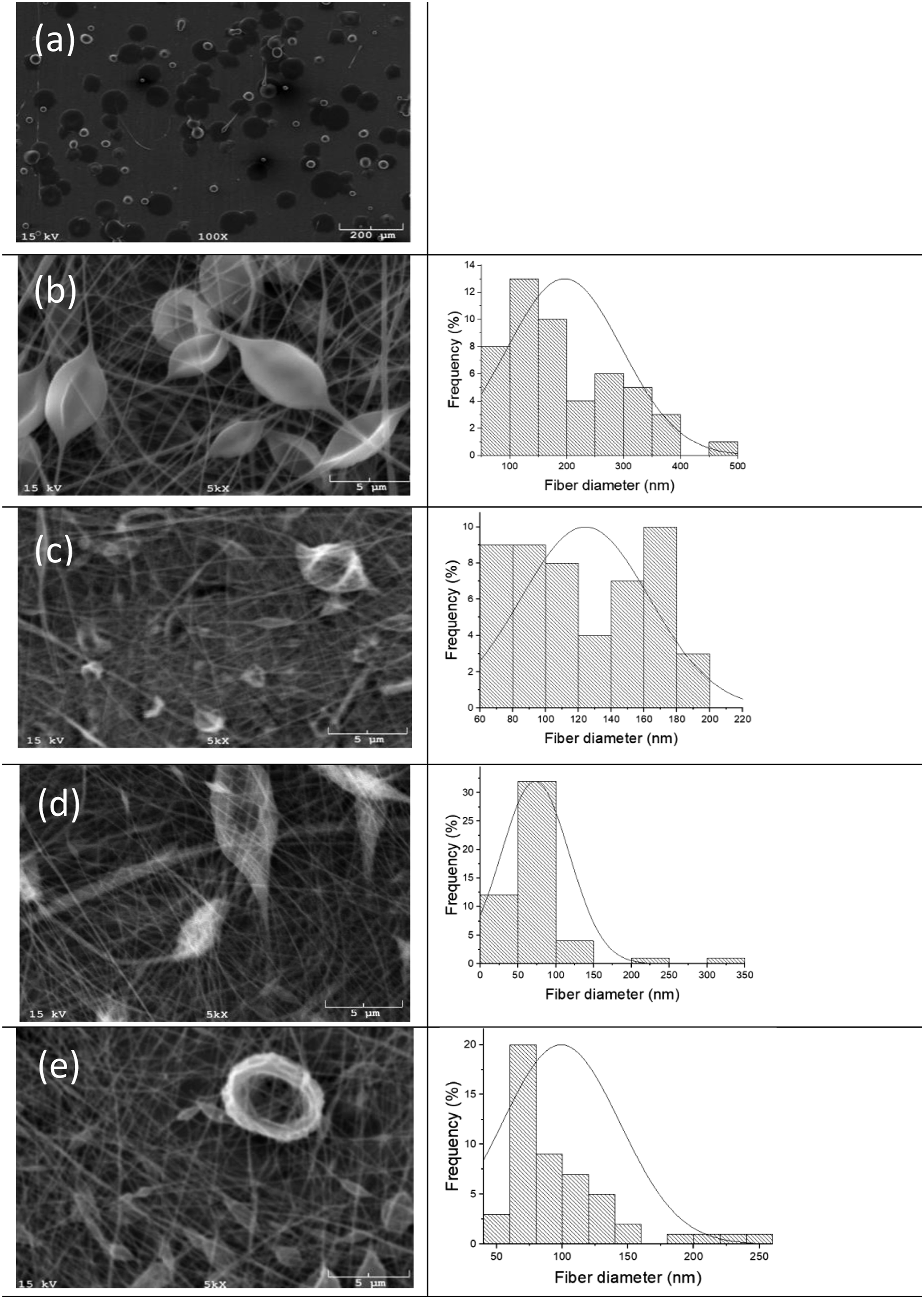
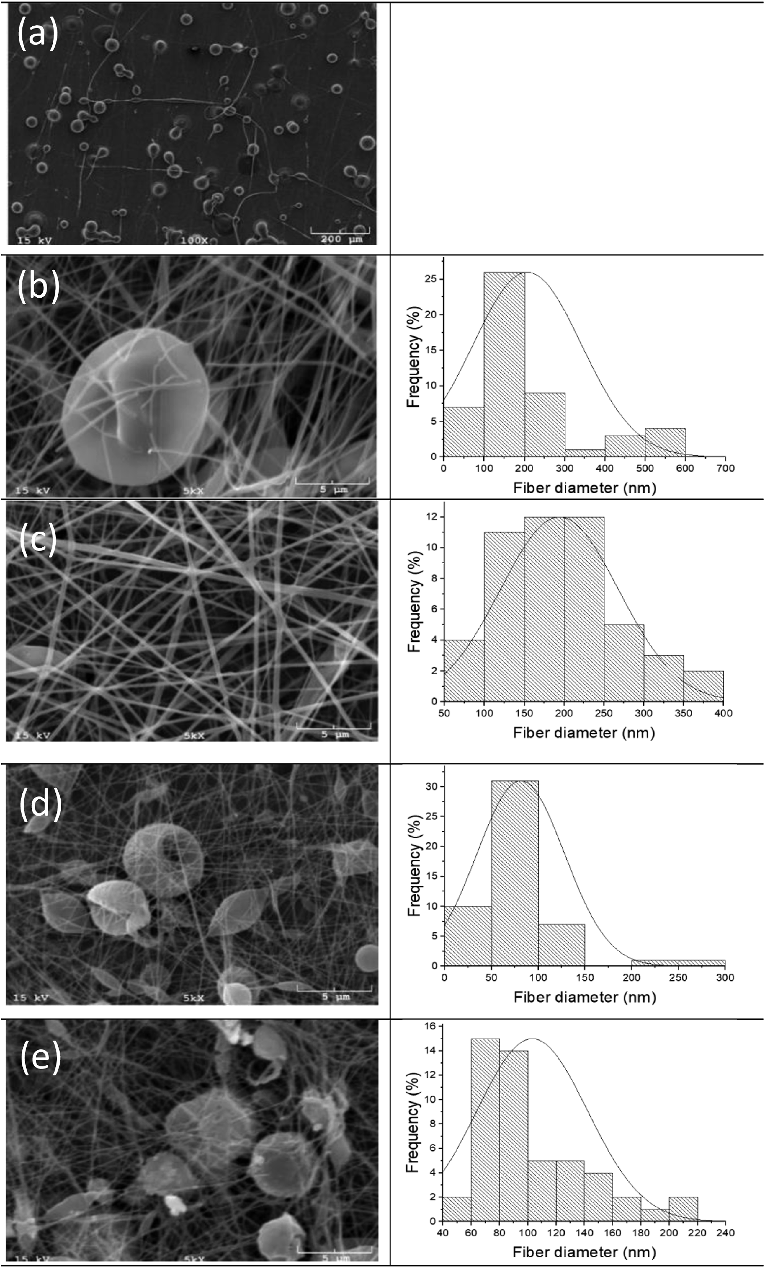


In Figures 1 and 2, showing the fiber structures produced from amorphous grades (aPLA-H and aPLA-L) at a concentration of 7.5 wt %, beads were observed almost at each solvent ratio. Bead formation was inevitable when an inherent amorphous structure and low polymer concentration were combined. On the other hand, dramatic changes on electrospinning parameters, that is, voltage, feed rate, and distance, could be implemented to improve the beaded fiber structure. However, electrospinning parameters were changed in a narrow range since it was aimed to exclude their effects on nanofiber production.
Viscosity values of the polymer solutions (mPa.s).

As could be compared in the SEM images of Figures 1(a), 2(a), and 3(a), only cPLA-H with 100% CHL led to the production of fibers. At 7.5 wt% concentration, sufficient number of entanglements did not form in the solutions prepared from aPLA-L and aPLA-H due to the amorphous structure of the polymers and low dielectric constant of CHL, hence only beads were formed (Figures 1(a) and 2(a)). This is while the crystallization of cPLA-H during injection could contribute to the molecular entanglements and caused the fiber formation (Figure 3(a)).
Since the dielectric constant of DMF is considerably more than that of CHL, the polymer jet carries more free charge and stretches more under an electric field.69,70 In addition, DMF has a higher boiling point, which increases the solvent evaporation time and provides the polymer jet with sufficient time for stretching. 71 Hence, at 7.5 wt. % concentration of amorphous PLAs, when the DMF content increased, the viscosity values of the polymer solutions decreased (Table 3), and the fiber diameter noticeably decreased (Figure 4). In a solvent ratio of 25/75 (CHL/DMF), the fiber diameter of amorphous PLAs decreased more and the finest fibers were obtained. As shown in Figure 4, the mean diameter for aPLA-L and aPLA-H were about 73 ± 44 nm and 81 ± 46 nm, respectively. When amorphous PLAs were dissolved in 100% DMF, aPLA-L and aPLA-H solutions at 7.5 wt% concentrations still resulted in fibers at nano scale. However, the mean fiber diameter produced from 100% DMF was higher than that produced from 25/75 (CHL/DMF). This is because the surface tension (35.0 mN/m) and viscosity (0.902 mPa.s) of DMF are higher than those of CHL, that is, 27.2 mN/m and 0.593 mPa.s, respectively. 71 Moreover, the solution viscosity of aPLA-L in 100% DMF was 62 ± 0.03 mPa.s, whereas it was 55 ± 0.09 mPa.s in 25/75 (CHL/DMF). Similarly, the solution viscosity of aPLA-H in 100% DMF was 66 ± 0.05 mPa.s, whereas it was 61 ± 0.01 mPa.s in 25/75 (CHL/DMF). Therefore, although the conductivity of DMF is high, the increased viscosity of DMF limited the stretching of the jet and produced coarser fibers. 72
Figures 5–7 illustrates the SEM images of aPLA-L, aPLA-H, and cPLA-H, respectively, at 10 wt% polymer concentration obtained with various CHL/DMF solution ratios, while Figure 8 compares their fiber diameters. In Figures 5 and 6, less beaded fibers were observed compared to Figures 1 and 2 since polymer concentration was increased from 7.5 to 10 wt. %. In addition, as noted earlier, due to the formation of a viscous gel at room temperature when using a high ratio of DMF (>50%), cPLA-H fibers were produced only at CHL/DMF solvent ratios of 100/0 and 75/25 which were given in Figure 7. Scanning electron microscope images and fiber diameter distribution of 10 wt% aPLA-L at various solvent concentrations. (a) aPLA-L-10/C100-D0, (b) aPLA-L-10/C75-D25, (c) aPLA-L-10/C50-D50, (d) aPLA-L-10/C25-D75, (e) aPLA-L-10/C0-D100. Scanning electron microscope images and fiber diameter distribution of 10 wt% aPLA-H at various solvent concentrations. (a) aPLA-H-10/C100-D0, (b) aPLA-H-10/C75-D25, (c) aPLA-H-10/C50-D50, (d) aPLA-H-10/C25-D75, (e) aPLA-H-10/C0-D100. Scanning electron microscope images and fiber diameter distribution of 10 wt% cPLA-H at various solvent concentrations. (a) cPLA-H-10/C100-D0 and (b) cPLA-H-10/C75-D25. Fiber diameters of 10 wt% cPLA-H, aPLA-H, and aPLA-L PLAs at various solvent ratios.
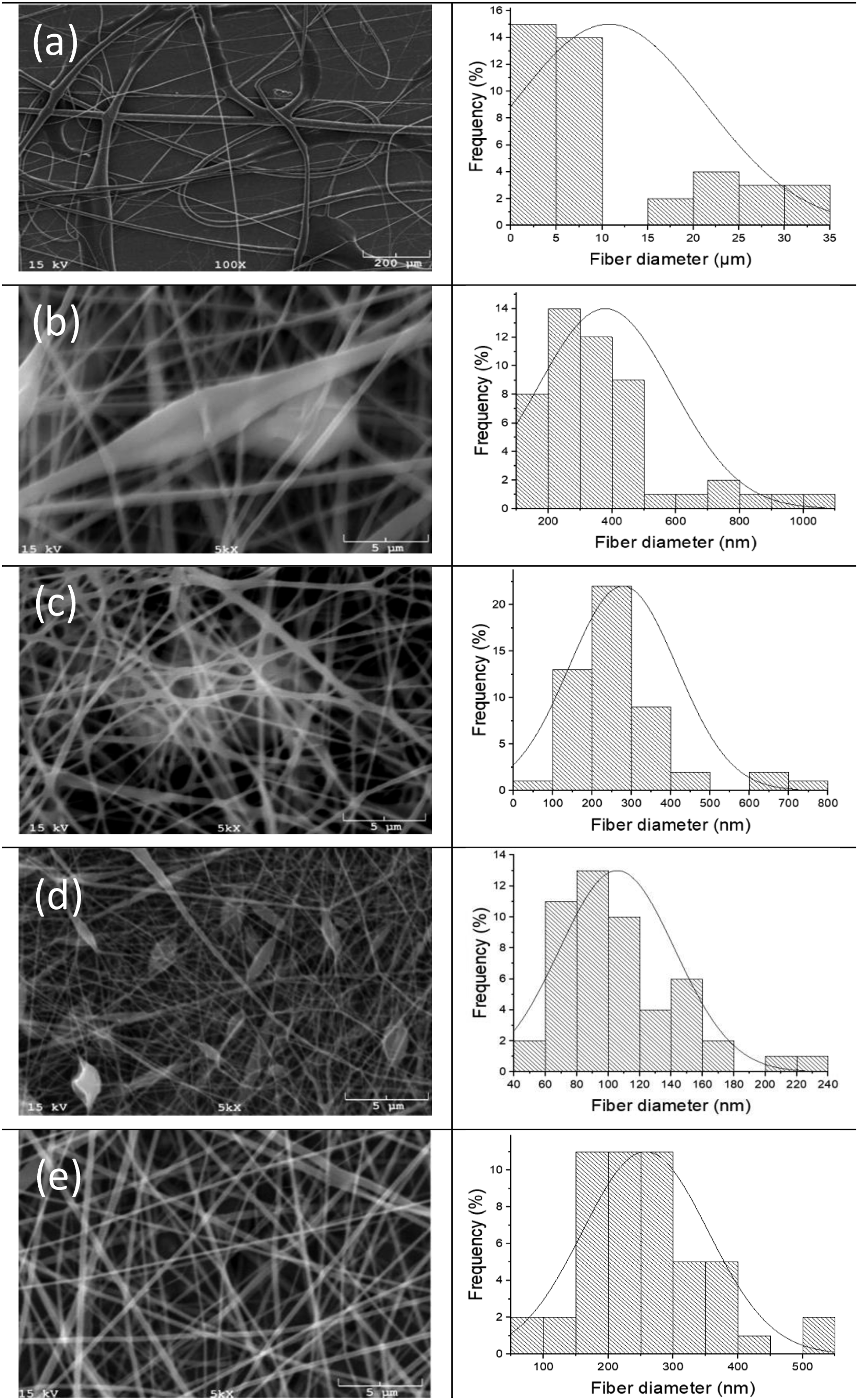
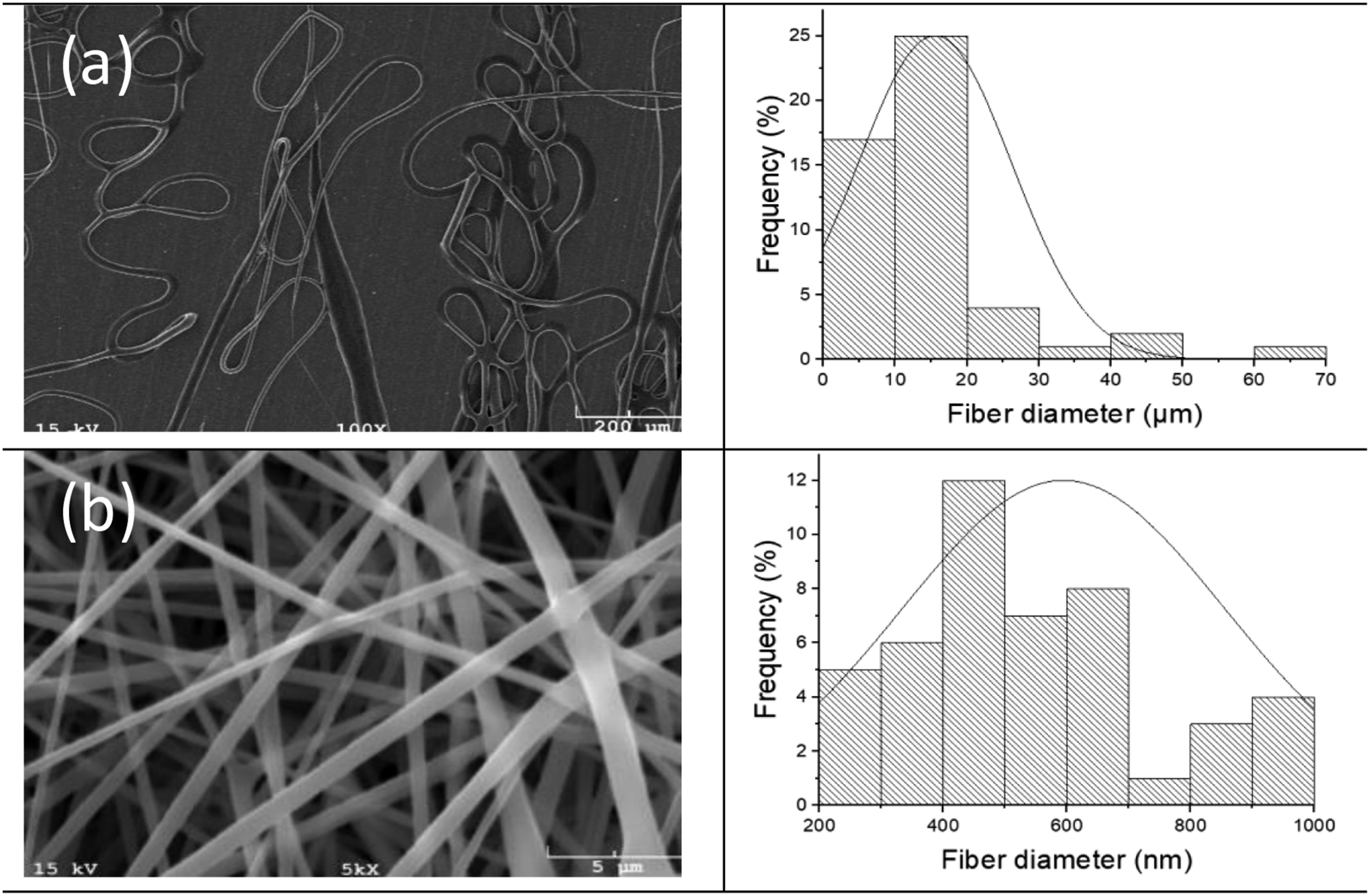
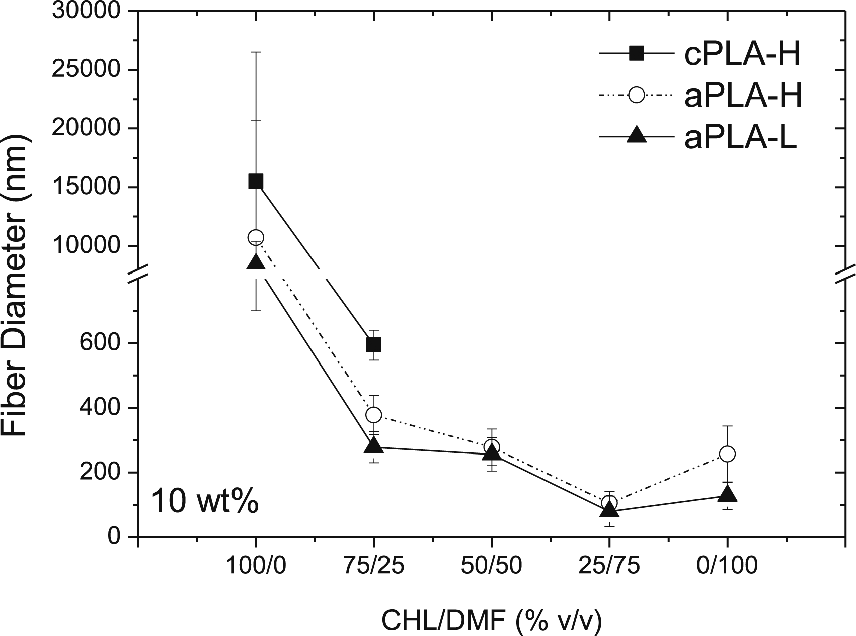
According to the SEM images shown in Figures 5(a), 6(a), and 7(a), all three types of PLA prepared with 100% CHL at 10 wt% polymer concentration yielded microfibers, due to low dielectric constant of CHL, and high solution viscosities (Table 3). In this context, at 10 wt.% polymer concentration with 100% CHL, the mean fiber diameters were around 15.5 ± 11 μm, 10.7 ± 10 μm, and 8.4 ± 2 μm for cPLA-H, aPLA-H, and aPLA-L, respectively (Figure 8). Even though both cPLA-H and aPLA-H have high and similar molecular weights, that is, 184 and 190 kg/mol, respectively, the polymer solution of cPLA-H had a higher solution viscosity, 184 ± 0.09 mPa.s, and produced much coarser fibers due to its crystallization during the fiber formation, which hinders the stretching to form thinner fibers. Nevertheless, it seems that the use of 100% CHL was not efficient since high volatility of CHL caused clogging of the needle during the electrospinning process. Moreover, since the dielectric constant of CHL is rather low, the polymer jet could not stretch enough to form fibers at nanoscale, and hence microfibers were produced. 71 Similar to those electrospun samples at 7.5 wt% concentration, the increase in DMF content in the solvent refined the fiber size and the finest fibers were obtained at the solvent ratio of 25/75 (CHL/DMF). At 10 wt. % concentration, the mean diameter of electrospun aPLA-L and aPLA-H was about 80 ± 47 nm and 105 ± 36 nm, respectively (Figure 8). As seen, aPLA-L revealed a finer fiber diameter than that of aPLA-H due to its lower molecular entanglement, which facilitates stretching and forming finer fibers. Moreover, compared to those at 7.5 wt% concentrations, it can be seen that an increase in the concentration caused the formation of coarser nanofibers due to the increased molecular interconnections. In other words, at higher concentrations, the increased viscoelastic force of the solution reduced bending instability of the polymer jet, which resulted in coarser nanofibers. 22 As presented in Figures 4 and 8, while aPLA-L and aPLA-H solutions at 10 wt% in 100% DMF resulted in fibers at nano scale, the increase in polymer concentration from 7.5 to 10 wt% increased the average diameter of fibers from 99 ± 44 nm to 128 ± 43 nm and from 103 ± 39 nm to 257 ± 87 nm for aPLA-L and aPLA-H, respectively. Similar trend was observed in other solutions prepared at different solvent ratios. As noted earlier, higher surface tension and viscosity of 100% DMF resulted in higher solution viscosity than that produced from 25/75 (CHL/DMF). In addition, the solution viscosity of aPLA-L in 100% DMF was 75 ± 0.08 mPa.s, whereas it was 59 ± 0.03 mPa.s in 25/75 (CHL/DMF). Similarly, the solution viscosity of aPLA-H in 100% DMF was 82 ± 0.06 mPa.s, whereas it was 69 ± 0.02 mPa.s in 25/75 (CHL/DMF). As a result, the mean fiber diameter produced from 100% DMF was higher than that produced from 25/75 (CHL/DMF) even though the conductivity of DMF is higher than CHL. 72
With the addition of 25% v/v DMF, the fiber diameter decreased from micro scale to nano scale and the problem of needle-clogging was resolved. The mean fiber diameters at 10 wt% polymer concentration in 75/25 ratio of CHL/DMF were about 594 ± 46 nm, 378 ± 61 nm, and 278 ± 48 nm for cPLA-H, aPLA-H, and aPLA-L, respectively (Figure 8). In Figure 9, SEM images of 10 wt% cPLA-H, aPLA-H, and aPLA-L samples in 75/25 CHL/DMF, at low magnification (500X), were given to compare their fiber structure in a large scale. As seen, cPLA-H showed bead-free morphology (Figure 9(a)), whereas aPLA-H and aPLA-L revealed some bead contents (Figures 9(b) and (c)). With the decrease in polymer concentration to 7.5 wt% in CHL/DMF solvent ratio of 75/25, the fiber diameters were about 291 ± 59 nm, 207 ± 65 nm, and 196 ± 50 nm for cPLA-H, aPLA-H, and aPLA-L, respectively (Figure 4). Although the fiber diameters further decreased in all three PLA grades, Figure 10 shows that more and larger beads were appeared among the fibers of all PLAs. While the fiber diameter reduced with a decrease in polymer concentration, cPLA-H showed the coarsest fiber diameter due to its high solution viscosity (Table 3), and the crystallization during the fiber formation. This is while the amorphous PLAs revealed finer fibers due to the absence of crystallization. The decrease in molecular weight in amorphous PLAs further caused the fiber diameter reduction due to the reduced viscosity and molecular entanglement in aPLA-L, which yielded the formation of finer nanofibers. In brief, even though both cPLA-H and aPLA-H possessed a high molecular weight, at a constant solvent ratio and polymer concentration, cPLA-H produced coarser fibers due to its high crystallizability. On the other hand, among amorphous PLA grades, at a constant solvent ratio and polymer concentration, aPLA-H produced coarser fibers than aPLA-L due to its higher molecular entanglement.
73
In all, an increased viscoelastic force due to more entanglements in the solution in relation with the presence of crystallites and high molecular weight limits the time for bending and stretching of polymer jet, which in turn, shortens the jet’s path from needle to collector and results in coarser fibers.
28
Scanning electron microscope images of three polylactide grades (10 wt%) in chloroform/dimethylformamide at solvent ratio of 75/25. (a) cPLA-H-10/C75-D25, (b) aPLA-H-10/C75-D25, and (c) aPLA-L-10/C75-D25. Scanning electron microscope images of three PLA grades (7.5 wt%) in chloroform/dimethylformamide at solvent ratio of 75/25. (a) cPLA-H-7.5/C75-D25, (b) aPLA-H-7.5/C75-D25, and(c) aPLA-L-7.5/C75-D25.

Water vapor transmission rate (WVTR)
Since all three types of PLA at a concentration of 10 wt% and in 75/25 (CHL/DMF) produced more uniform solid mats with more uniform fibers (Figure 9), these samples were selected for the characterization of the electrospun nanofiber mats. WVTR was incorporated to analyze the porosity of the produced electrospun mats. This is because the WVTR is affected by the nature of polymer (hydrophobicity/hydrophilicity and degree of crystallinity), and the pore size of electrospun mats.
74
It was previously reported that high degree of crystallinity reduces the solubility and permeability of water because crystallites act essentially as inert fillers that are impermeable to penetrants.75,76 Accordingly, it may be expected that cPLA-H presents lower WVTR than amorphous PLAs as previously reported for solution casted films.
75
However, Figure 11 shows that cPLA-H sample revealed a higher WVTR than amorphous PLAs. This is a result of thicker fiber obtained from cPLA-H. Therefore, it is shown that the WVTR is dominated mainly by the structure of the pores rather than the degree of polymer crystallinity. Accordingly, aPLA-L with finer fiber morphology depicted the lowest WVTR value among other PLAs. Water vapor transmission rates (WVTR) of the electrospun mats.
DSC analysis
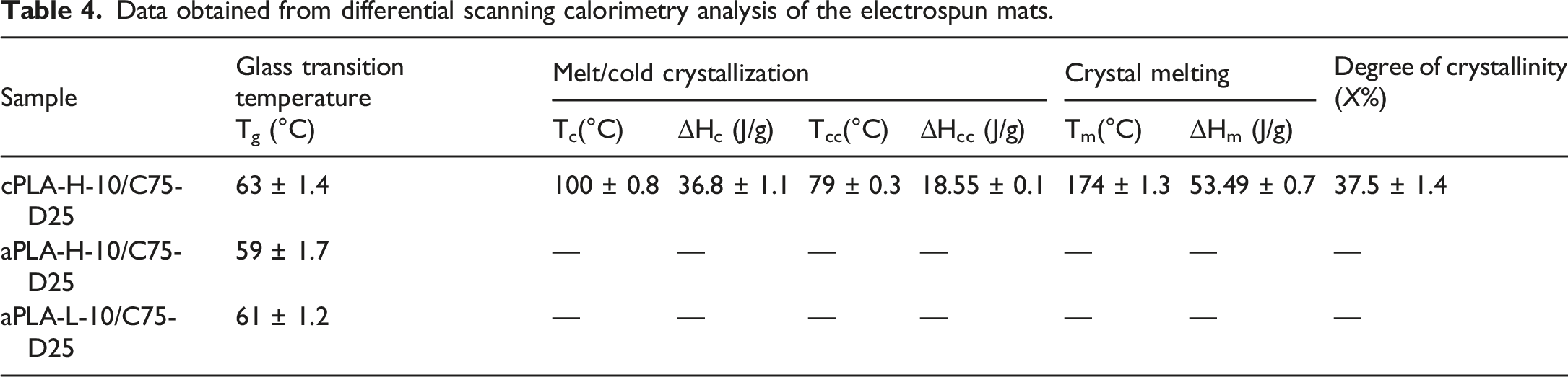
Figure 12 illustrates the DSC heating and cooling thermograms of the electrospun mats of cPLA-H, aPLA-H, and aPLA-L. The glass transition (Tg), melt and cold crystallization (Tc and Tcc), and crystal melting (Tm) temperatures, and degree of crystallinity of the electrospun samples were reported in Table 4. As shown, cPLA-H electrospun fibers contained around 37% of crystallinity indicating the significance of crystallization during the fiber formation, which hinders the formation of finer fibers. As expected, aPLA-H and aPLA-L did not show any crystallinity even under such stretching force during the fiber formation. It was obvious that the Tg of cPLA-H sample was higher than those of the other samples since the crystallites in the structure restrict the regularity of the amorphous region.
68
However, although the Tg of aPLA-H was expected to be higher than that of aPLA-L, the chance of maintaining more residual solvent in the high molecular weight PLA might have lubricated the molecules of aPLA-H more noticeably than that of aPLA-L and hence caused further Tg reduction.
77
Differential scanning calorimetry heating (a) and cooling (b) thermograms of electrospun mats. Data obtained from differential scanning calorimetry analysis of the electrospun mats.
Dynamic mechanical analysis
Figure 13 illustrates the effect of temperature on the storage and loss moduli of the electrospun samples, respectively. For all samples, the storage moduli were higher than the loss moduli indicating the elastic behavior of the investigated samples. The storage modulus of cPLA-H was higher than those of amorphous PLA samples due to the presence of certain content of crystallinity (∼37%).
78
On the other hand, aPLA-L showed lower storage modulus compared to other samples due to its lowest molecular entanglement. For all three samples, while the storage modulus was high in the glassy region,79,80 it significantly reduced with the increase in temperature beyond the Tg. This is while the storage modulus of cPLA-H was still higher beyond the Tg due to the existence of crystallinity. According to the loss moduli, it can be seen that despite the values reported in the DSC analysis, the Tg values are in a good agreement with the nature of PLA samples. As seen, cPLA-H revealed the highest Tg value due to its high molecular weight and existence of certain degree of crystallinity. aPLA-L sample also possessed the lowest Tg due to its low molecular weight compared to aPLA-H. The difference between the values obtained from DSC and DMA results could be attributed to the different operating principles of DMA, a dynamic mechanical technique, and DSC, an instrumental thermal analytical technique.81,82 In this context, loading frequencies and heating rates of the experiment could affect the Tg values.
83
The slow heating rate in DMA might have already caused the evaporation of residual solvent in PLA samples, which could differently affect the results obtained from those of DSC. Storage (a) and loss (b) moduli of electrospun mats.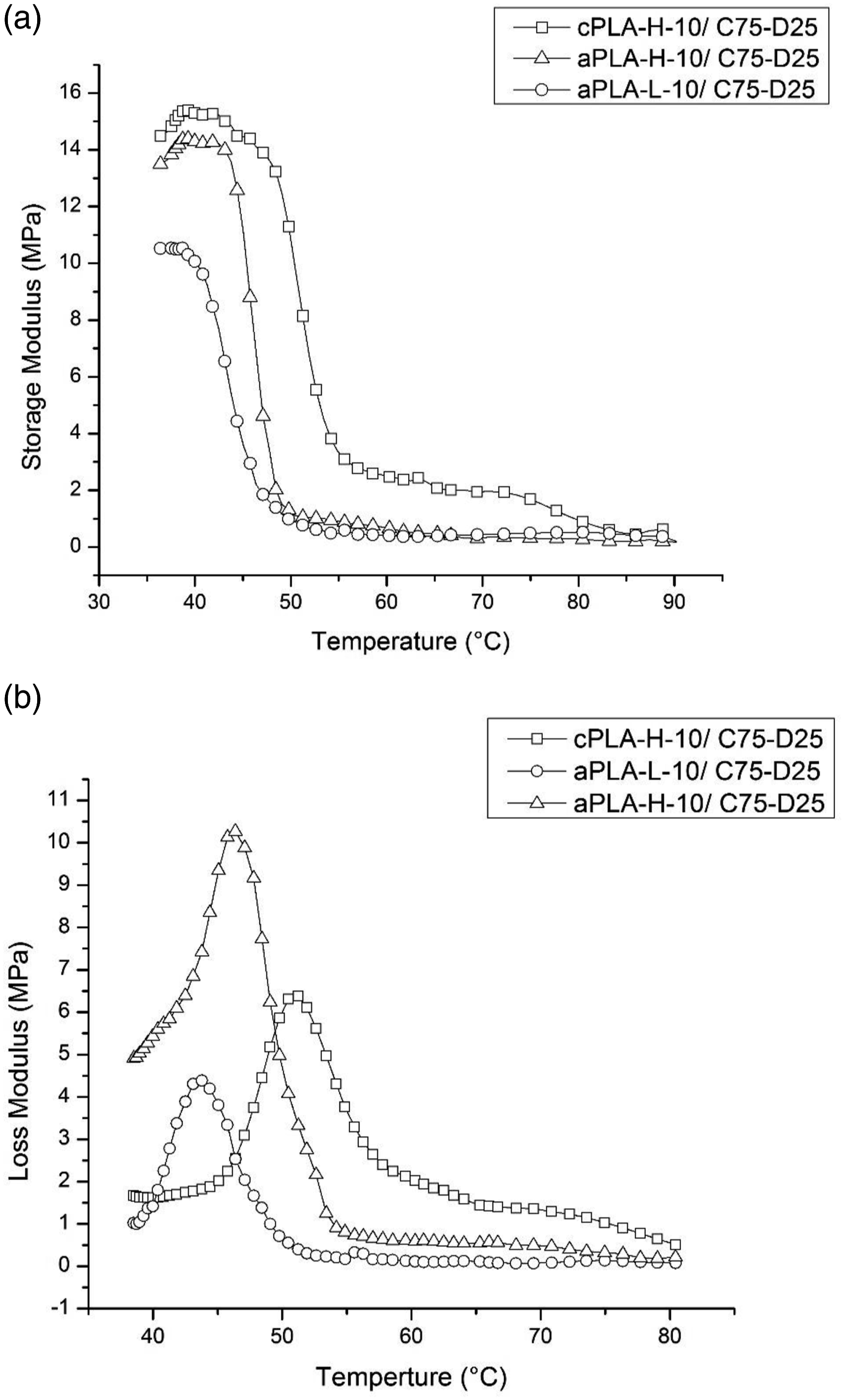
Tensile strength
Tensile strength, elongation at break, and Young’s modulus values of the electrospun mats of cPLA-H and aPLA-H samples are given in Figure 14. It should be noted that viable tensile test results could not be obtained with aPLA-L sample due to its weak structure as a possible result of fine fiber morphology, with an average fiber diameter of 278 ± 48 nm, together with its low molecular weight and amorphous structure. No significant difference was observed between the tensile strength performance of cPLA-H and aPLA-H.
84
This could be due to the inherent properties of the PLA samples as well as the obtained electrospun nanofiber morphologies. In other words, the large content of crystallinity (∼37%) in cPLA-H sample and the finer fiber morphology (378 ± 61 nm in diameter) in aPLA-H sample with more interconnections between the fibers allowed these samples to resist a tensile force of approximately 7N. On the other hand, it was observed that aPLA-H showed lower elongation at break (∼59%) compared to cPLA-H (∼69%). This might also be due to the beaded electrospun fibers in aPLA-H, which could limit its elongation at break.
85
In addition, cPLA-H sample showed higher Young’s modulus compared to aPLA-H due to the presence of certain content of crystallinity. Tensile strength (a), elongation at break (b), and Young’s modulus (c) values of the electrospun mats of cPLA-H and aPLA-H samples.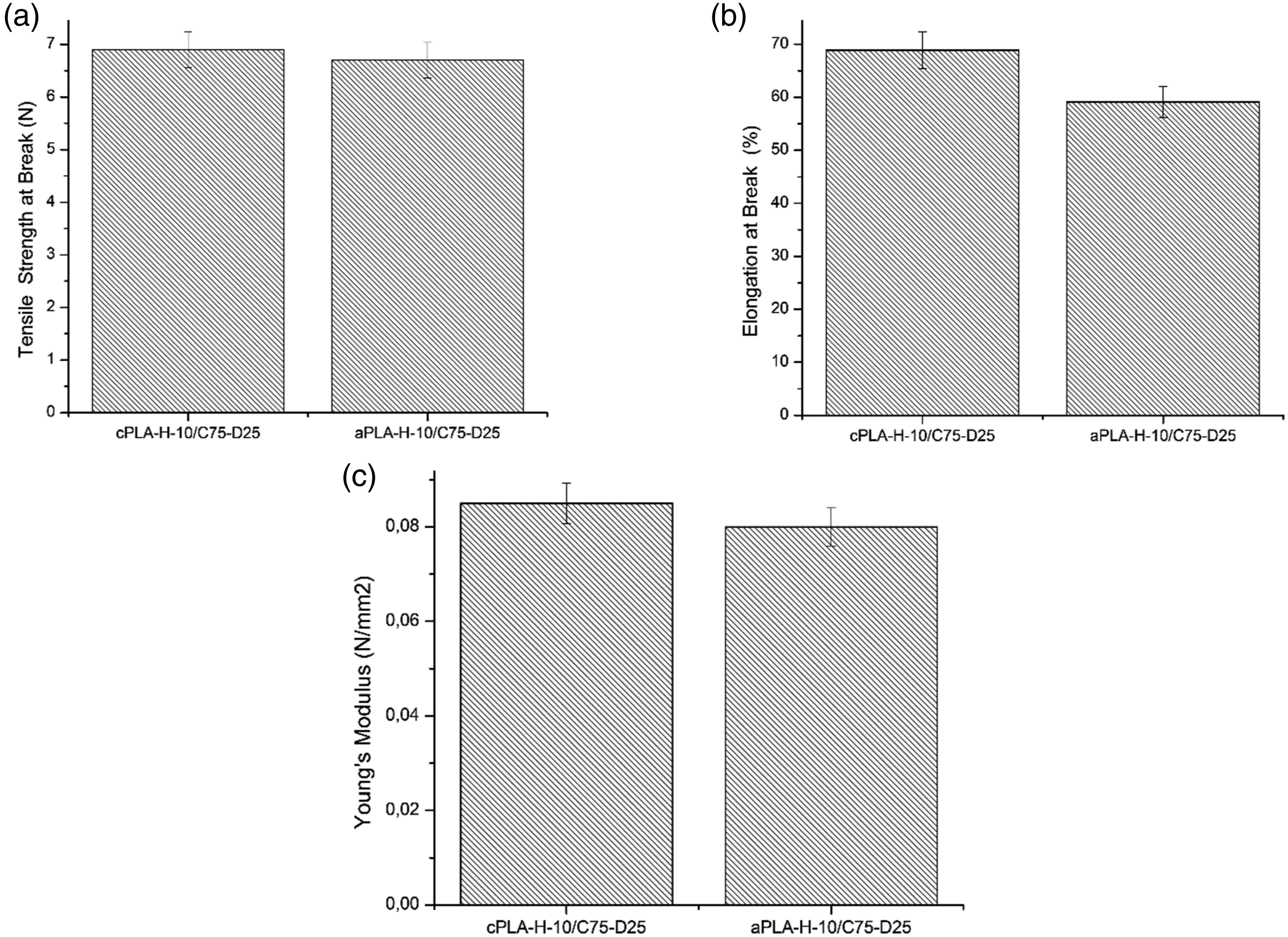
Conclusion
This paper revealed the effects of D-lactide content and molecular weight of PLA on its electrospinning behavior and characteristic of produced electrospun mats. At a constant solvent ratio and polymer concentration, aPLA-H always produced coarser fibers than aPLA-L due to its higher molecular entanglement as a consequence of its higher molecular weight. Even though both cPLA-H and aPLA-H had a similar high molecular weight, at a constant solvent ratio and polymer concentration, cPLA-H yielded coarser fibers due to the crystallization during the fiber formation, which limits its further stretching. The DSC analysis confirmed the formation of about 37% of crystallinity in cPLA-H. The higher WVTR of cPLA-H sample also confirmed its larger pores with thicker fibers. In contrast, aPLA-L with much finer nanofiber structure showed the lowest WVTR value among other PLAs. The storage modulus of cPLA-H was higher than those of amorphous samples due to the presence of certain content of crystallinity. According to the loss modulus peaks, it was confirmed that the Tg of the samples reduced with the increased D-lactide content and the decreased molecular weight. The tensile properties illustrated that cPLA-H and aPLA-H samples revealed similar tensile strength as both the inherent properties of the PLA and the formed fiber structures could concurrently affect such mechanical performance of the electrospun mats.
In summary, at the same concentration, although cPLA-H showed a uniform fiber morphology and better mechanical performance, coarser fibers were formed due to the crystallization during the electrospinning. In addition, processing window of cPLA-H was much narrower due to limited solubility in solvents, which further hindered its electrospinnability. The dissolubility and processability of amorphous grades were better than cPLA-H. However, the bead formation was observed in electrospun mats of amorphous grades. In order to eliminate the bead formation, the polymer concentration of amorphous grades could be increased (>10 wt%), which means polymer consumption will be higher. As a conclusion, even if it is possible to produce electrospun mats from each three different PLA grades successfully, limitations of each grade in electrospinning process and the characteristics of their electrospun mats must be taken into consideration for their selection in further studies.
Footnotes
Declaration of conflicting interests
The author(s) declared no potential conflicts of interest with respect to the research, authorship, and/or publication of this article.
Funding
The author(s) received no financial support for the research, authorship, and/or publication of this article.