
Abstract
Electrospinning is one of the most effective ways of preparing nanofibers with a broad spectrum of potential applications. Its products can be used in air filtration, oil-water separation, sensors, carbon dioxide capture, supercapacitor, lithium-ion batteries, catalysts, tissue engineering, drug delivery, enzyme immobilization, and in many other fields. In this review, the mechanism, basic setup, and processing parameters are presented. Different kinds of methods for mass preparation and production devices are summarized and compared. Applications of electrospun nanofibers in different fields are also briefly discussed.
Keywords
Introduction
Nanofibers are fibers with diameters in the nanometer range (1-1000 nanometers) and exhibit many unique properties, such as large surface area, compared with other known materials.1–3 There are many methods to prepare nanofibers such as stretching, template synthesis, phase separation, self-assembly, molecular spinneret spinning, and electro-spinning.4–9 Among these methods, electrospinning is the most simple and effective method for generating nanofibers.
Electrospinning Mechanism and Basic Setup
In 1934, Formhals invented a device for producing polymer fibers by electrostatic repulsion and applied for a patent. This was the first detailed description of the device for producing polymer fibers by high-voltage electrostatic force. This is recognized as the beginning of electrospinning technology for preparing fibers. 10 The electrospinning device consists of three basic parts: (i) high-voltage power supply, (ii) spinneret, and (iii) receiving device as illustrated in Fig. 1.
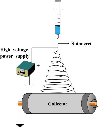
Schematic diagram of electrospinning device.
Electrospinning has become one of the main ways to effectively prepare nanofibers due to the advantages of a simple manufacturing device, low spinning cost, various kinds of spinnable materials, and good process controllability. Electrospinning technology is based on high-speed injection of conductive fluid under a high-voltage electrostatic field. During the spinning process, the polymer solution or melt becomes a cone (Taylor cone) when high-voltage current is applied. The electrostatic force on the polymer solution or melt can overcome the surface tension when the applied voltage reaches the critical value
Electrospinning Parameters
The electrospinning process is influenced by many factors, with major factors being environment parameters (temperature and humidity), spinning polymer parameters (viscosity, molecular weight, molecular structure, conductivity, concentration, solvent, and feed rate), and electrostatic field (voltage, spinneret, collector, and distance).
The influence of temperature and humidity on electros-pinning is mainly reflected in fiber diameter and the fiber formation. For solution electrospinning, the change of temperature and humidity can affect the solvent evaporation rate and viscosity of the solution. Higher temperatures may contribute to solvent evaporation and reduce the viscosity of the solution, and a thinner fiber can be obtained with greater ease. 14 The influence of humidity on electrospinning is more complex than that of temperature as two opposing influences on fiber diameter occur when only one parameter changes. Both higher or lower humidity can lead to an increase or decrease in fiber diameter; solvents used, as well as polymer species are all related to this.15,16 For melt electrospinning, humidity does not play a significant role during fabrication, but when the humidity is too high, it can cause air breakdown and even the device damage caused by the high-voltage loads.17,18 The effect of temperature on melt electrospinning is reflected in melt temperature (nozzle temperature) and spinning temperature, as both of them show strong influences on the average fiber diameter. As the temperature increases, the diameter of fibers has a tighter distribution,19,20 and, therefore, it is advantageous for preparing uniform-sized nanofibers.
Viscosity, as a basic fluid property, is an important parameter in both solution electrospinning and melt electrospinning. It is determined by many properties of polymers, such as molecular weight, molecular structure, concentration, solvent, and temperature. 21 As the viscosity increases, the critical voltage of initiation spinning increases.22,23 Depending on molecular weights, molecular structures, solution concentrations, and solvents, the fiber diameter, distribution, and morphology show significant differences.24–26 During electrospinning, a suitable feed rate determines the distribution of fiber diameter and throughput of the fiber; an increase in fiber diameter and the formation of droplets are related to excessive feed speed.19,27,28 The effect of conductivity on electrospinning is very basic, as it determines whether the polymer can be electrospun or not, based on the surface charge on the fluid droplet.29,30 For polymers with low conductivity, salts can be added to improve conductivity. Increased conductivity was shown to improve the spinnability and the quality of the fibers.31,32
Electric fields play a key role in the electrospinning process. Spinning voltage, spinning distance, and the shape and distribution of the spinneret and collector can affect the electric field intensity and distribution.33–35 In most cases, a higher spinning voltage leads to greater stretching, which can reduce the fiber diameter. 36 Many simulations and experiments about the conditions of spinning distance, spinneret and collector have been carried out for mass production of electrospun nanofibers.37–41 The spinning distance mainly affects the drawing time of the fibers, and a larger spinning distance is beneficial to the further drawing of the fibers. Too large or too small spinning distances are not conducive to spinning and fiber collection.42–48 To summarize, whether the critical voltage is high or low, or the spinning distance is big or small, there must be a series of optimal parameters for each polymer, and there must be a balance between the various parameters.
Preparation of Electrospun Nanofibers
To increase the output of electrospun nanofibers and obtain more functional nanofiber assemblies, many modifications have been made in the basic electrospinning devices. The modified electrospinning devices can be divided into two categories according to the spinning method: multi-needle multi-jet spinning and needleless multi-jet spinning.
Multi-Needle Multi-Jet Spinning
Multi-needle multi-jet spinning can be used for mass production of nanofibers by arranging a certain number of needles according to a specific array. There are two common arrangements: one-dimensional linear array and two-dimensional array. In the multi-needle electrospinning device, the interference of electric field between needles is the limiting factor affecting mass production of electrospinning nano-fibers. Therefore, the interference of electric field between needles should be minimized by adjusting the arrangement of needles when the spinning device is designed.
One-Dimensional Linear Array
A one-dimensional linear array is a way in which multiple needles are arranged according to a one-dimensional structure. By designing multiple needles, the number of jets increases, thereby increasing the productivity of nanofibers. Park et al. developed a robot-assisted angled multi-nozzle electrospinning set-up and compared the simulation and the experimental results. The study showed that by controlling the number and distribution of the spinneret, the fiber diameter could be regulated more easily. 49 Kim et al. developed a novel upward cylindrical-type electrospinning system with a 1-m length cylinder-type nozzle, which had 120 multi-nozzles installed into a cylinder block module. 34 The fabrication of polyurethane (PU) nanofibers showed a fast and convenient production and the investigation suggests that this electrospinning system can be applied for mass production of nanofibers on both laboratory and fabrication scale. Although the above modification can significantly increase the fiber yield, there is still some electric field interference between needles, which hinders the spinning fluid from forming a stable jet. In addition, when the spinning fluid forms a jet, because of the mutual exclusion between the jets, instability of the jet is increased, which makes defects in the fiber membrane more prone to occur.
Two-Dimensional Array
The two-dimensional array is a planar array formed by distributing needles in the same plane according to different shapes. Polygon, circle, and ellipse arrays are the most common two-dimensional array types. Varesano et al. used a multi-jet electrospinning system with 2 to 16 nozzles to prepare polyethylene oxide nanofibers. The results showed that the divergence angle between the jets could be reduced by adding a secondary electrode. Good quality nanofibers were obtained in this study. 50 Theron et al. studied the electric field distribution in multi-nozzle electrospinning by using linear and non-linear Maxwell models. The theoretical calculation and experimental results showed that the trajectory of charged jets changed due to Coulomb force interference—jets in the middle position were compressed, while jets at the edge were defected due to Coulombic repulsion. 37 Jets defections in the linear arrangement of the seven spinnerets occurred, and the fiber uniformity in the resulting fiber membrane was poor. The arrangement of nine-spinnerets in a square array could improve fiber uniformity. When the distance between the spinnerets was reduced, the deposition speed of the fiber in a small area accelerated and at the same time, good quality nanofiber membrane were obtained when the voltage and the receiving distance were increased. Yang et al. designed multi-nozzle electrospinning equipment with an equilateral hexagon array. A coaxial shield ring was used to ensure a uniform electric field at the tip of the spinnerets and to restrict the receiving area on the collector. 51 The results showed that the outside spinnerets were beneficial for forming a uniform electric field at the inside spinnerets. The multi-needle spinnerets were very robust and uniform nanofibers were produced by this system. These distributions of needles show the scale up possibility for mass production of nanofibers by using an equilateral hexagon array with a shield ring.
The above research showed that the interference of electric field between spinnerets still occurred in both one-dimensional array as well as two-dimensional array multi-needle electrospinning. Although the interference between electric fields can be reduced by using spinneret arrangements and auxiliary devices, improvements were still limited.
Needleless Multi-Jet Spinning
Needleless multi-jet spinning is essentially different from multi-needle spinning. By using a needleless method, the spinning solution or melt was placed in an open area. When the voltage was applied, numerous charged jets were formed at the surface of the spinning solution or melt and the purpose of increasing nanofiber output was achieved. According to the motion state, all the spinnerets can be divided into motionless spinnerets and moving spinnerets.
Motionless Spinnerets
Zheng et al. studied plate spinnerets and developed a porous plate spinneret electrospinning device with a uniform electric field. The experimental results showed that the electric field can be kept stable when the number of orifices was increased, and the porous spinning device slowed down the jet displacement compared with the same number of multi-needle electric fields. This provided an important theoretical support for the mass production of nanofibers. 52 He et al. first put forward the bubble electrospinning technology, which has been put into production now. Although the voltage required for bubble spinning is low, the diameter dispersion of the fibers is large because of the uncontrollable size of the bubbles. 53 A novel and efficient stepped pyramid-shaped spinneret was developed by Jiang et al. 54 The jets were generated on the edges of the step, under a given polymer concentration and receiving distance during the process of electrospinning. This greatly increased nanofiber productivity with the increase of the spinning voltage and was viewed as beneficial to the development of needleless electrospinning and mass production of nanofibers. 54 Wang et al. reported a conical metal wire-coil as spinneret which can be used at voltage as high as 70 kV without causing corona discharge. In addition, a finer nanofiber can be prepared by this device. 55
Moving Spinnerets
Lu et al. reported a needleless electrospinning setup using an electriferous rotating cone as the spinneret. The production throughput of this approach was about 10 g/min; a great improvement compared with a single needle as the spinneret. 56 Lee et al. designed a cylinder type electrospinning device; this cylinder type mass production system was more productive than the single spinneret spinning device. 57 Niu et al. studied the difference between two spinnerets: a rotating disk and a rotating cylinder. a rotating disk spinneret spun with a lower voltage, and the fibers were finer than those generated from a rotating cylinder. Meanwhile, the simulation results showed that the electric fled on the disk was more uniform than that on the cylinder, and the intensity at the edge of the disk was higher than that at the edge of the cylinder. 58
From the above analysis, use of needleless multi-jet electrospinning greatly mitigated the problems of spinneret blockage and non-uniform electric field intensity during needle electrospinning. However, due to instability and uncontrollability of the needleless multi-jet electrospinning jet, further research is needed on morphology control of nanofiber assemblies.
Industrial Electrospinning Setups
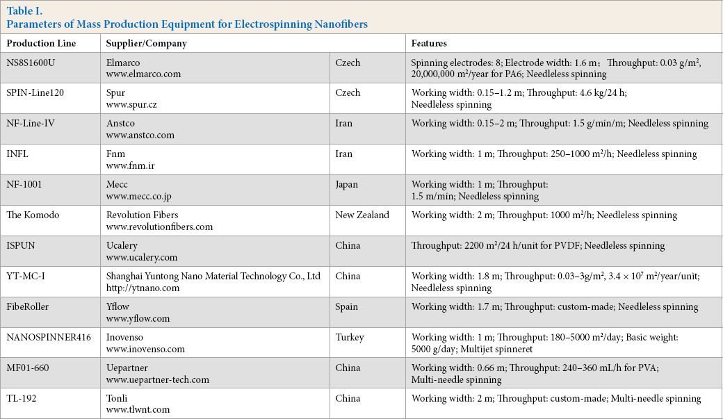
With the continuing development of electrospinning technology, researchers in many countries are devoting themselves to mass production of electrospun nanofibers. Table I shows some representative electrospinning equipment.
Parameters of Mass Production Equipment for Electrospinning Nanofibers
Applications of Electrospun Nanofibers
Electrospun nanofibers are widely used in many fields. In this article, we mainly consider environmental, energy, medical, and sensor applications.
Environmental Applications
The applications of electrospun nanofibers in the environmental field mainly include filtration, oil-water separation, and water treatment. Wang et al. presented a multilevel structured polyacrylonitrile/silica nanofibrous membrane for high-performance air filtration; the results suggested that this is a cost-effective filter media and promising materials for air filters. 59 Gopal et al. reported a membrane which can be used in the pre-treatment of water; it can reject more than 90% of particles in solution. 60 Arslan et al. developed modified electrospun cellulose acetate nanofibers (CA-NF), which showed superhydrophobic properties and was practical for water/oil separators. 61
Energy Applications
The dimensionality, directionality, and compositional flexibility of electrospun nanofibers are increasingly being investigated for the targeted development of cells and electrolyte supercapacitors. Tamura et al. synthesized a novel proton exchange membrane fuel cell composed of sulfonated polyimide nanofibers and sulfonated polyimide. The composite membrane had good oxidative and hydrolytic stability for use in fuel cells. 62 Kim fabricated a supercapacitor using electrospun polybenzimidazol (PBI) nanofibers, after carbonization at 800 °C. The nanofibers had a large specific surface area and capacitance and the system test showed that this was an excellent supercapacitor. 63
Medical Applications
A very interesting and practical study by Turaga et al. treated a biodegradable poly(vinyl alcohol) electrospun nanoweb with honey, and the tests suggested that this composite material can be used for medical textiles such as bandages. 64 Blakeney et al. fabricated a new three-dimensional cotton ball-like electrospun scaffold with excellent performance compared with the traditional electrospun scaffold; it had a similar diameter, but larger pores and less-dense structure, compared to the traditional electrospun scaffolds. 65 In addition, electrospun nanofibers can also be used for drug delivery, 66 functional wound dressings, 67 and antimicrobial air filtration masks. 68
Sensor Applications
The specific surface area of electrospun nanofibers offers unique opportunities in fabricating sensors. Ding et al. successfully prepared a new gas sensor consisting of an electrospun nanofiber membrane and quartz crystal microbalance (QCM) for ammonia detection. 69 It showed a very high sensitivity compared to continuous films coated QCM sensors. Wang et al. presented a preparation method for a high-sensitivity optical sensor, which combines electrospinning technology with electrostatic layer-by-layer adsorption technology. The high sensitivity of the sensor was attributed to the high surface area to volume ratio of the electrospun membrane and the effective interaction between fluorescent conjugated polymers and analytes. 70 In addition to the above sensor applications, electrospun nanofibers can also be used for humidity sensors, fluorescence sensors, glucose sensors, as well as others.71–73
Conclusion
Nanofibers are widely-used nanomaterials, and electrospinning is the most direct and effective method to prepare nanofibers. With the continuous development of electro-spinning technology, the application scope of electrospun nanofibers will gradually penetrate into more fields, including the food industry, national defense, chemical engineering, and new energy fields. There has been great progress and development in electrospinning equipment for mass production. Undoubtedly, electrospun nanofibers will become a potential nanomaterial in the near future.
Footnotes
Acknowledgement
The authors would like to thank The Hong Kong Polytechnic University for the financial support of this work.