
Abstract
The main purpose of this study was to investigate effects of various electrospinning parameters on the morphology and diameter of cellulose nanofibril (CNF) filled polylactide (PLA) nanofibers. For this purpose, first of all effects of three important electrospinning parameters; polymer solution concentration, solution feeding rate and collector distance to feeding tip were studied. Then, effects of using higher amount of CNF, effects of using cellulose nanocrystal (CNC) particles, and effects of adding potassium chloride salt were also investigated. It was observed that when optimum electrospinning parameters were determined, then it was possible to obtain almost “bead-free” morphology and “finest” average diameter of 232 nm for PLA/CNF electrospun fibers. Increasing values of feeding rate and collector distance parameters resulted in bead formation and thicker diameters. On the other hand, increasing CNF amount, using CNC particles and adding KCl salt, all resulted in further decreases in the diameter down to 152 nm; mainly due to increased charge density of the polymer solution. Moreover, in vitro degradation analysis of all types of electrospun nanofiber mats in a simulated body fluid revealed that increasing the immersion period increased their degradation rate in terms of “% weight loss”. It was also observed that, mats with fine diameter fibers had higher degradation rate.
Keywords
Introduction
Cellulose is the most abundant, renewable and sustainable biomaterial on Earth; being the basic constituent of all plants. For instance, it is present in the cell wall of wood along with hemicellulose and lignin. Although, there are various industrial applications of macro and micron sized cellulose fibrous forms; use of nano-sized cellulose structures as the biofillers of biopolymer matrices in the production of bio-nanocomposites are emerging.1–4
As shown in Figure 1, two basic nanocellulose structures obtained by using mechanical and chemical top-down processing techniques are cellulose nanofibrils (CNF) and cellulose nanocrystals (CNC) with diameters up to 100 nm. CNF composed of both amorphous and crystalline regions in its fibrous form have rather a high aspect ratio, while CNC consists of low aspect ratio crystalline particles with very little amorphous part.5–7 Two different nanocellulose structures (CNF and CNC) used as fillers in biocomposites.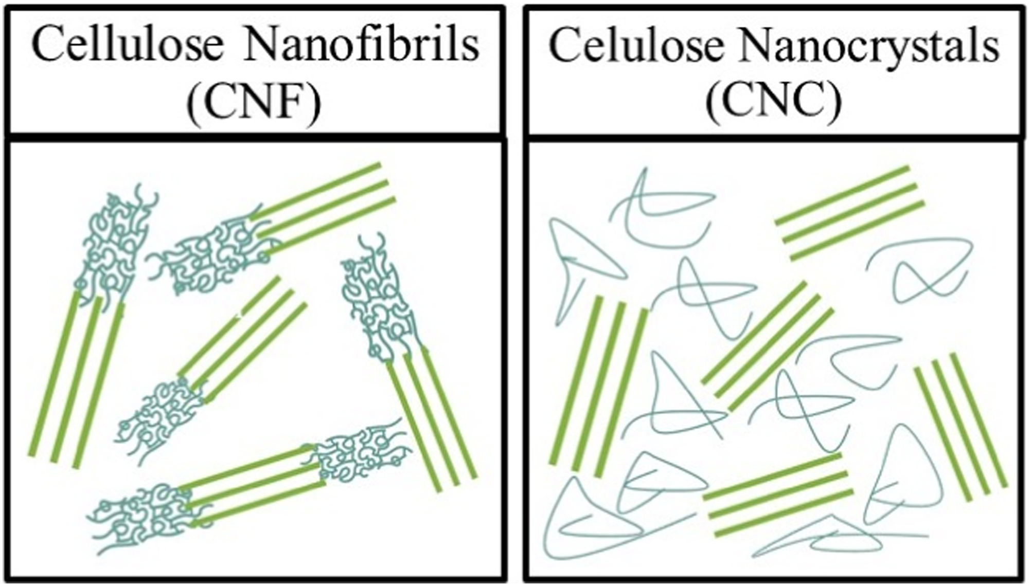
In the production of fully “green composites”; both the polymer matrix and the reinforcing fillers should be bio-sourced renewable ones. Although there are other alternatives, the most widely used biopolymer matrix selected in the bio-nanocomposite studies is polylactide (PLA).8–10
CNF or CNC filled PLA bio-nanocomposites could be obtained by using certain techniques such as “melt mixing” or “solution mixing” for various purposes. On the other hand, for certain biomedical applications such as wound dressing; fibrous forms would be necessary. For this purpose, “electrospinning” is being considered as the most effective nanofiber production technique. 11
As illustrated in Figure 2, during pumping the polymer solution to the feeding tip, high voltage power supply creates electrostatic field which charges the polymer solution. At this point, charged polymer solution droplets would be under opposite forces of viscoelastic forces and surface tension. Typical electrospinning system indicating important processing parameters.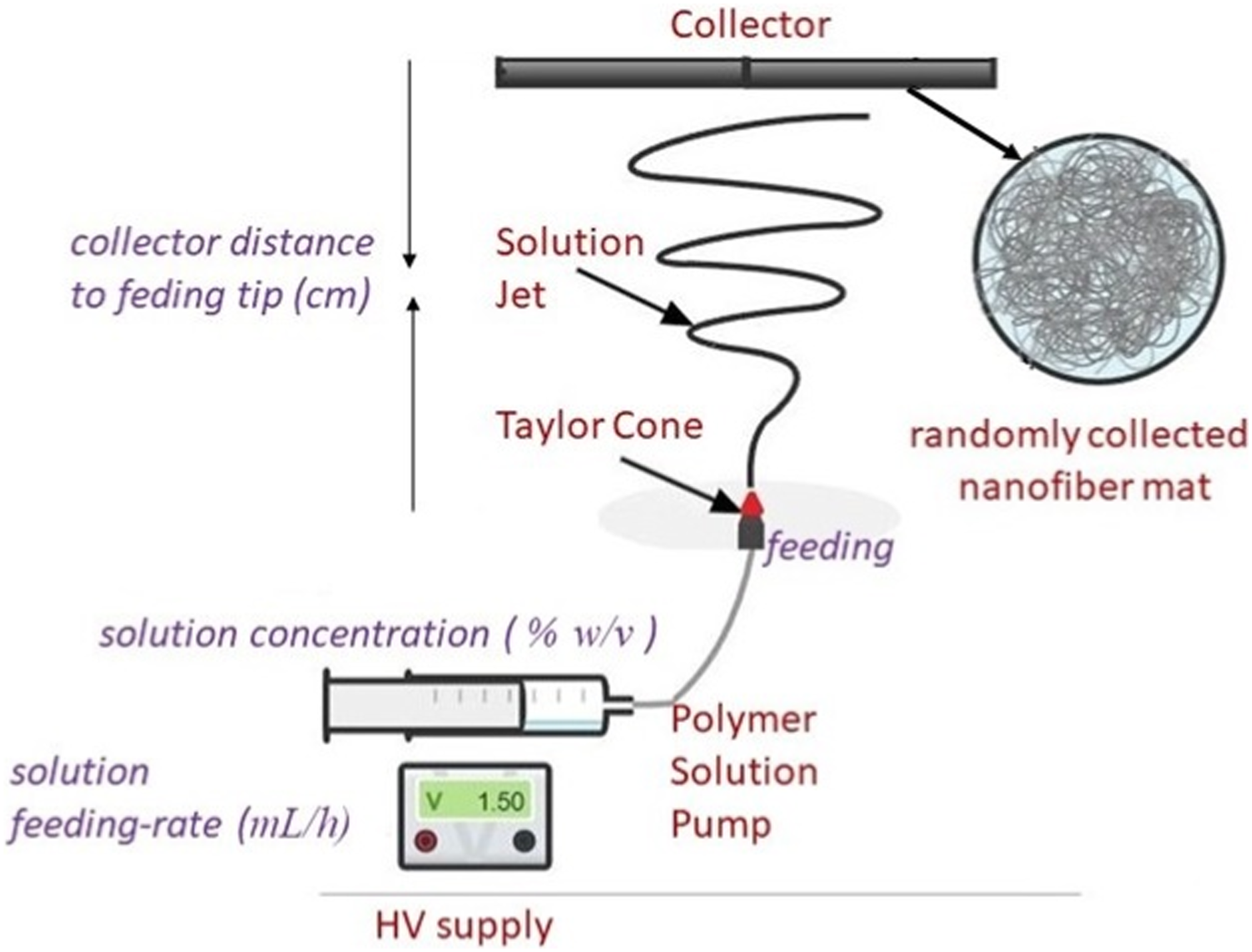
When the first one exceeds the other one, solution droplets would transform into a conical form (Taylor Cone). During the upward whipping motion of the solution jet, solvents would evaporate. Then, electrospun nanofibers would be deposited on a grounded collector.12,13
It is known that, in many biomedical applications, use of electrospun nanofibers with as much as lower diameter would be advantageous. Because, decreasing the fiber diameter would increase their total surface area required for certain chemical or biological interactions. It should be noted that, decreasing fiber diameter could also increase the degradation rate.
Therefore, the main purpose of this study was to investigate the effects of various parameters on the morphology and diameter of nanocellulose (CNF and CNC) filled polylactide (PLA) electrospun nanofibers. For this purpose, first of all effects of three important electrospinning parameters (Polymer Solution Concentration, Solution Feeding Rate, Collector Distance to Feeding Tip) were studied for the 1 wt% CNF filled PLA. Then, effects of 3 wt% CNF use compared to 1 wt%; effects of CNC use compared to CNF; and effects of KCl salt addition for all combinations were also investigated. Moreover, in vitro degradation rate of all types of electrospun nanofiber mats were compared.
Literature survey indicated that although there are several number of studies14–21 on the various aspects of electrospinning of PLA/CNF and PLA/CNC; only very limited number of them were focused on the effects of certain parameters influencing diameter of their electrospun fibers.
For example, Yang et al.22,23 studied effects of different amounts of CNF; while Xiang et al., 24 Liu et al., 25 Patel et al., 26 Rahmat et al. 27 and Shi et al. 28 studied effects of different amounts of CNC on the diameter of PLA based electrospun fibers. They generally indicated that increasing the amount of CNF or CNC in the polymer solution decreased the diameter of electrospun fibers; mainly due to the increased charge density of the polymer solution having higher amount of hydroxyl groups present in the cellulose structures.
It is known that, in order to increase electrical conductivity of polymer solutions, organic or inorganic salts could be added. In the literature, there are certain number of studies29–31 adding certain salts into neat or filled PLA solutions to observe their effects on the electrospun fibers. However, no studies were reported for CNF and CNC filled PLA solutions.
As stated above, size of the electrospun fibers play critical role in terms of in vitro degradation behavior. In the literature although there are limited number of degradation studies32–36 conducted for neat and filled PLA based electrospun fibers; no research was reported for the in vitro degradation of PLA/CNF, and only one study was reported for PLA/CNC by Shi et al. 28
Therefore, to the best of our knowledge, this work would be the first study not only investigating the effects of KCl salt addition on the electrospun fiber diameters of PLA/CNF and PLA/CNC; but also investigating the effects of fiber diameter on the in vitro degradation behavior of PLA/CNF biocomposite mats.
Experimental work
Materials used
The base biopolymer used in the electrospinning solution was polylactide (PLA) having L-lactic acid macromolecular structure (NaturePlast PLE 001, France). It has a density of 1.25 g/cm3, melting temperature range of 145-155°C, degradation temperature range of 240-250°C, and melt flow index range of 2-8 g/10 min at 190°C under 2.16 kg. Its average molecular weight was 101x103 g/mol.
Two different nanocellulose particles added to the PLA based electrospinning polymer solution were nanocellulose fibrils (CNF) and nanocellulose crystals (CNC). Diameter range of the particles given by the supplier (Guilin Qihong Technology, China) was 20-100 nm, in which CNF particles having slightly higher aspect ratio compared to CNC.
Other chemicals used in the preparation of electrospinning solution, i.e. chloroform (CF), dimethylformamide (DMF), potassium chloride (KCl) were all high purity grade (Fluka, Germany).
Generally in nanocomposite studies, the amount of the filler incorporated into the matrix polymer is around 1 wt%. Consequently, the amount of both CNF and CNC added into the PLA matrix solution were chosen as 1 wt%; i.e., 99 wt% PLA and 1 wt% CNF or CNC. For simplicity, these combinations were designated as PLA/CNF and PLA/CNC through the manuscript. Effects of using 3 wt% CNF was also investigated.
Electrospinning procedures
Equipment
As shown in Figure 3, electrospun nanofibers were obtained by using a single-nozzle vertical electrospinning equipment (NanoSpinner Ne100, Inovenso Inc., Turkey). The capacity of high voltage power supply was up to 40 kV, while the capacity of the polymer solution pump via a disposable syringe was up to 10 mL/h, so that it was possible to investigate effects of solution feeding rate. A polyethylene capillary tube connects the syringe and the needle having inner diameter of 0.8 mm. Between the collector and feeding tip of the polymer solution jet, the distance was 25 cm, thus it was decided to also investigate another important electrospinning parameter, i.e., collector distance to feeding tip. The collector of the equipment was stationary type round aluminum plate. In order to collect electrospun nanofibers easily; collector was also covered with aluminum foils. By using the air ventilation system of the equipment, it was possible to keep temperature and relative humidity of the cabin at about 30°C and 40%, respectively. General view of the electrospinning equipment used.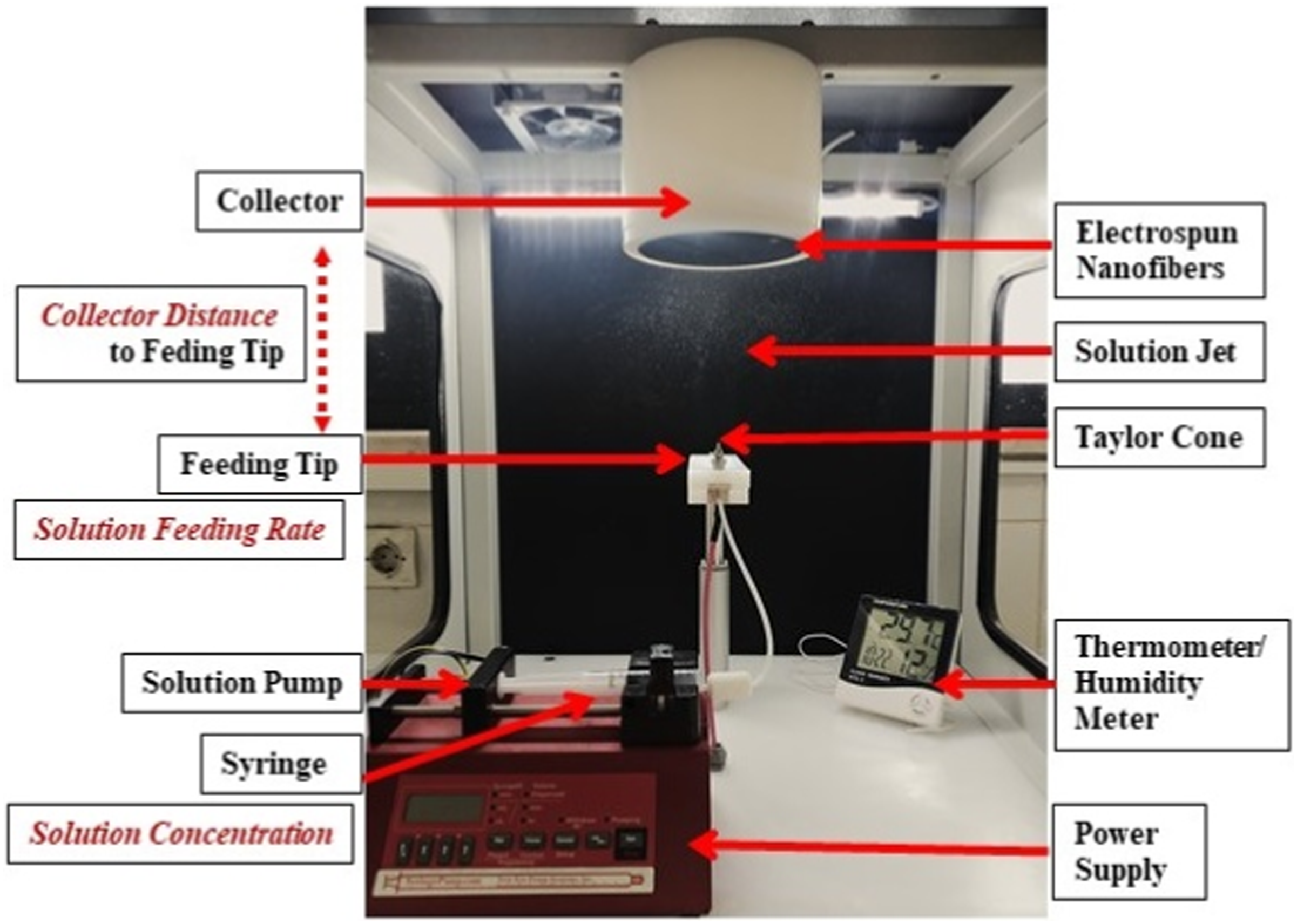
Preparation of the polymer solutions
It is known that use of CF and DMF as 75/25 v/v solvent ratio is very effective during electrospinning of PLA based polymer solutions. Therefore first, CF/DMF solvent mixtures (3:1) were prepared as 10 mL, which was the capacity of polymer syringe of the equipment. Then, certain amount of PLA granules were dissolved in this mixture by magnetic agitation at 30°C with 600 rpm for 4 hours. After that, required amounts of nanocellulose particles were added to the dissolved PLA solution with further mixing of 2 hours. Moreover, PLA/nanocellulose solutions were also ultrasonicated to obtain well-dispersed cellulose nanoparticles just before the start of electrospinning process.
Viscosity and conductivity measurements of the polymer solutions
Since viscosity (i.e., polymer concentration) and charge density (i.e., electrical conductivity) of polymer solutions influence morphology and diameter of the electrospun fibers, these two parameters were also measured at 25°C before the start of electrospinning. Viscosity of polymer solutions were measured using a digital viscosimeter (Brookfield DV-II + Pro, USA); while electrical conductivities were measured via a benchtop conductivity meter (Hanna HI 2315, USA).
Obtaining electrospun nanofibers
After preparing PLA/nanocellulose polymer solutions properly, and measuring their viscosity and conductivity, electrospinning processes were conducted by using different process parameters as would be discussed later in the manuscript. After each experiment, electrospun nanofibers were collected in the form of “mat” on the aluminum foil surface covering the collector. In order to use these electrospun fiber mats in the further analysis, their thickness and amount should be similar. For this reason, electrospinning period used during each experiment was determined according to the Solution Feeding Rate. For instance, for the feeding rates of 0.9, 1.5, 1.8 mL/h; total electrospinning period used were 30, 18 and 15 minutes, respectively.
Diameter analysis of electrospun fibers
Before diameter determination, it should be stated that scanning electron microscopy (FEI Nova Nano 430, USA) analysis was first conducted for the surface morphology of electrospun fibers including bead formation.
Diameter analysis of electrospun fibers were conducted in two steps. First, scanning electron microscopy was used to take various numbers of general and closer view SEM images of electrospun fibers collected in the form of mats on aluminum foil surfaces. Then, average diameter of the electrospun fibers were measured by using an image analysis software (ImageJ, USA) on at least 300 randomly selected individual fibers present on the SEM images.
In Vitro degradation analysis of electrospun fibers
Since electrospun biocomposite fibers have been considered for many biomedical applications, it is important to analyze in vitro degradation behavior of these electrospun samples in a simulated human body fluid. For this purpose, electrospun nanofibers in the form of mat were cut into 15 × 15 mm square samples. Then, samples were immersed in a physiological saline solution up to 12 weeks in an oven at 37°C human body temperature (Figure 4). Before that, phosphate-buffered saline (PBS) tablets (Sigma Aldrich, USA) were dissolved in 200 mL deionized water to prepare the solution, so that it would be composed of 0.01 M phosphate buffer, 0.0027 M potassium chloride and 0.137 M sodium chloride with the required pH value of 7.38 at 25°C. General and closer views of in vitro degradation of electrospun fiber mats.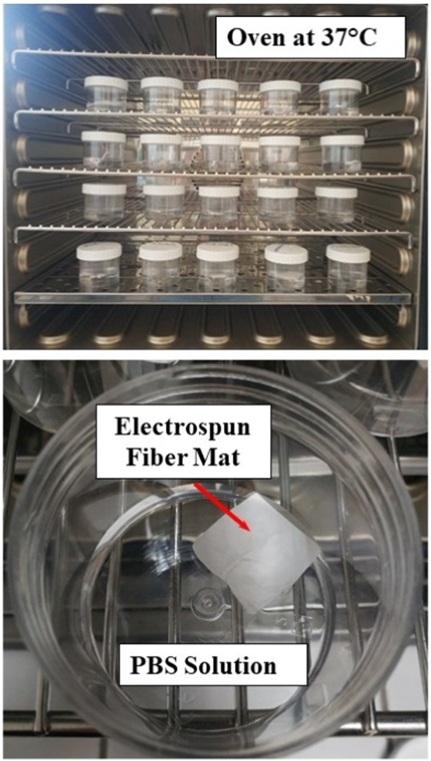
At the end of each week, in order to determine degree of degradation, electrospun fiber mat samples were taken out of their solution bottles, dried and then weighed with a precision balance to calculate “% weight loss” values.
Results and discussion
It is known that the most critical four processing parameters during electrospinning of polymer solutions are;
(i) Applied Voltage (kV)
(ii) Polymer Concentration in the Solution (%w/v)
(iii) Solution Feeding Rate (mL/h)
(iv) Collector Distance to Feeding Tip (cm)
Depending on the electrospinning equipment, the most widely used applied voltage for many polymer solutions were in the range of 10-20 kV; being generally around 15 kV for neat and filled PLA based solutions.24,25,28,31 Thus in this study, applied voltage level selected was also 15 kV for the electrospinning of PLA/CNF solutions. For the three other critical processing parameters, various experimental procedures applied were discussed in the following sections.
Effects of PLA/CNF concentration in the solution
Electrospinability of polymer solutions first of all depends on mainly formation of proper Taylor cone and stable polymer solution jet; in which both of them are influenced directly by the “viscosity” that is “polymer concentration” of the solution. Otherwise, it would be very difficult for the polymer solution jet to reach the collector and form nanofibers.
Studies14,19,31 on the neat and filled PLA based solutions indicated that typical range for the polymer solution concentrations was 5-15 %w/v. In this study, it was decided to try three different PLA/CNF concentration values as 6, 8 and 10 %w/v. Before electrospinning, viscosity values of these three solutions were measured in terms of cP.
Figure 5 shows conditions of Taylor cone and solution jet formations together with the concentration and viscosity values of PLA/CNF solutions. It was observed that when PLA/CNF concentration was 10 %w/v (viscosity 308 cP), there were significant degree of clogging at the solution “feeding tip” blocking the formation of Taylor cone and polymer solution jet, so that electrospinning was not possible. Images showing effects of PLA/CNF concentration or viscosity of the solution on the formation of Taylor cone and polymer solution jet.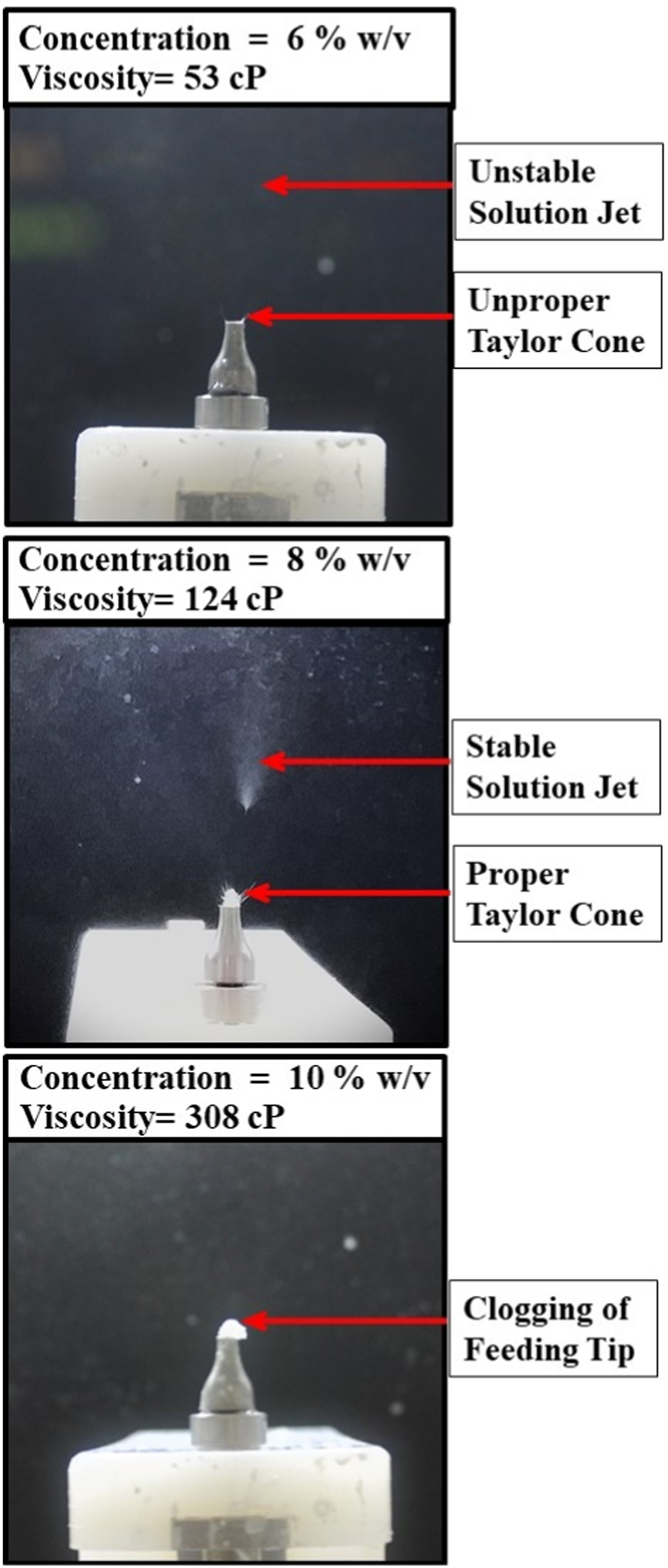
When PLA/CNF concentration was 6 %w/v (viscosity 53 cP) or 8 %w/v (viscosity 124 cP); then formation of Taylor cone and solution jet were possible. On the other hand, it was revealed that when concentration was 8 %w/v, more proper Taylor cone and more stable solution jets were formed compared to the concentration of 6 %w/v. Then, in order to choose PLA/CNF concentration as 6 or 8 %w/v to use in the further experiments, electrospun fiber mat samples formed on the collector were examined under SEM.
Figure 6 indicated that when concentration was 6 %w/v, there was mainly formation of “droplets”, not fibrous form. Because, it was discussed that
37
use of lower polymer concentration or lower solution viscosity might prevent to get sufficient amount of polymer macromolecules to overcome electrostatic stretching forces. Then, polymer jets split up leading to formation of droplets. SEM images showing effects of solution concentration on the formation of PLA/CNF droplets or beaded fibers.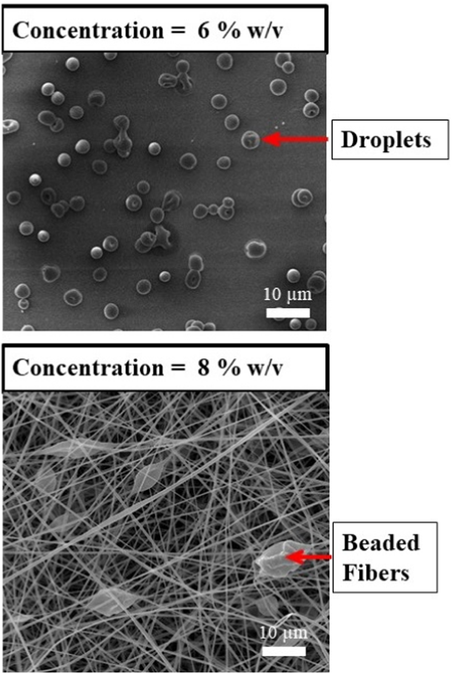
On the other hand, use of 8 % w/v concentration resulted in formation of “fibrous” morphology. It was seen in Figure 6 that, many of the electrospun fibrous forms have no smooth structure; instead, there were so many numbers of “beads” on their surfaces. Thus, it was interpreted that in order to obtain “bead-free” PLA/CNF electrospun fibers, other processing parameters should be studied; as discussed in the next section.
Effects of solution rate and collector distance on the bead-free PLA/CNF fibers
Researchers26,27,31 on the electrospinability of neat and filled PLA based solutions revealed that when polymer concentration was around 8 %w/v, then in order to obtain electrospun fibers with smooth surfaces; typical range used for solution feeding rate parameter was between 0.5-2.0 mL/h, while typical range for collector distance to feeding tip parameter was 10-25 cm. Thus, in this study to obtain bead-free smooth electrospun PLA/CNF fiber morphology, various experiments were conducted by using the following three different values for each processing parameter: • PLA/CNF Solution Feeding Rate: 0.9, 1.5, 1.8 mL/h • Collector Distance to Feeding Tip: 15, 18, 20 cm
After electrospinning of PLA/CNF solutions with various combinations of these two parameters, it was generally observed that increasing the solution feeding rate and increasing the collector distance both resulted in formation of certain numbers of beads. From this point of view, it could be stated that the worst combination leading to beaded morphology was solution feeding rate of 1.8 mL/h and collector distance of 20 cm. For the almost bead-free morphology, the best combination was solution feeding rate of 1.5 mL/h and collector distance of 15 cm. Example SEM images for each combination was illustrated in Figure 7. SEM images showing effects of solution rate and collector distance on the formation of beaded and bead-free electrospun PLA/CNF fibers.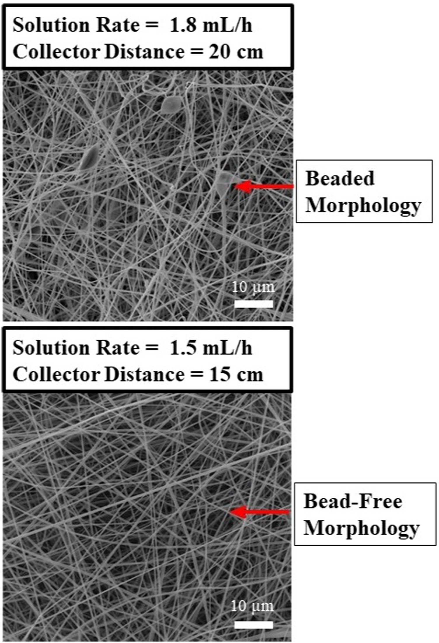
As would be discussed in the next sections, main reasons for the beaded morphology and thicker diameter levels observed for the electrospun PLA/CNF fibers were similar.
Effects of solution rate and collector distance on the diameter of PLA/CNF fibers
Since the optimum combination for the bead-free morphology of electrospun fibers was solution feeding rate of 1.5 mL/h and collector distance of 15 cm, then effects of these two parameters on the diameter of PLA/CNF nanofibers were investigated by keeping one of these optimum values as constant and changing the other; which made up six different combinations. Then, average diameter analysis for these combinations were conducted as described in the experimental work section.
In order to reveal effects of solution feeding rate parameter, Figure 8 shows general and closer SEM images including measured average fiber diameters obtained by increasing the solution feeding rate values while keeping the collector distance value constant at 15 cm. Similarly, for the effects of collector distance, Figure 9 indicates SEM images and average fiber diameters obtained by increasing the collector distance values while keeping the solution feeding rate value constant at 1.5 mL/h. General and closer SEM images showing effects of solution feeding rate on the average diameter of PLA/CNF electrospun fibers when collector distance was kept as 15 cm. General and closer SEM images showing effects of collector distance on the average diameter of PLA/CNF electrospun fibers when solution feeding rate was kept as 1.5 mL/h.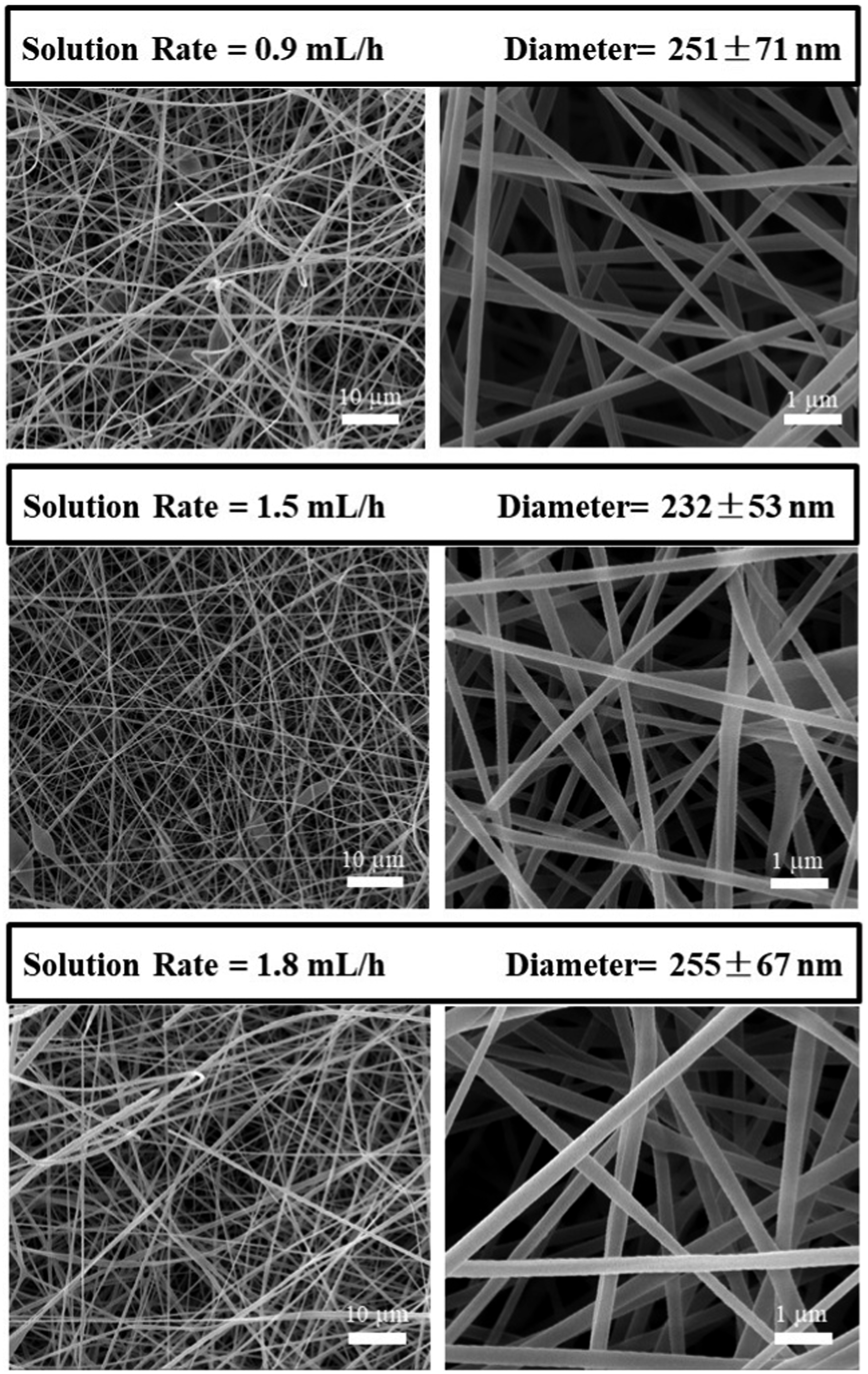
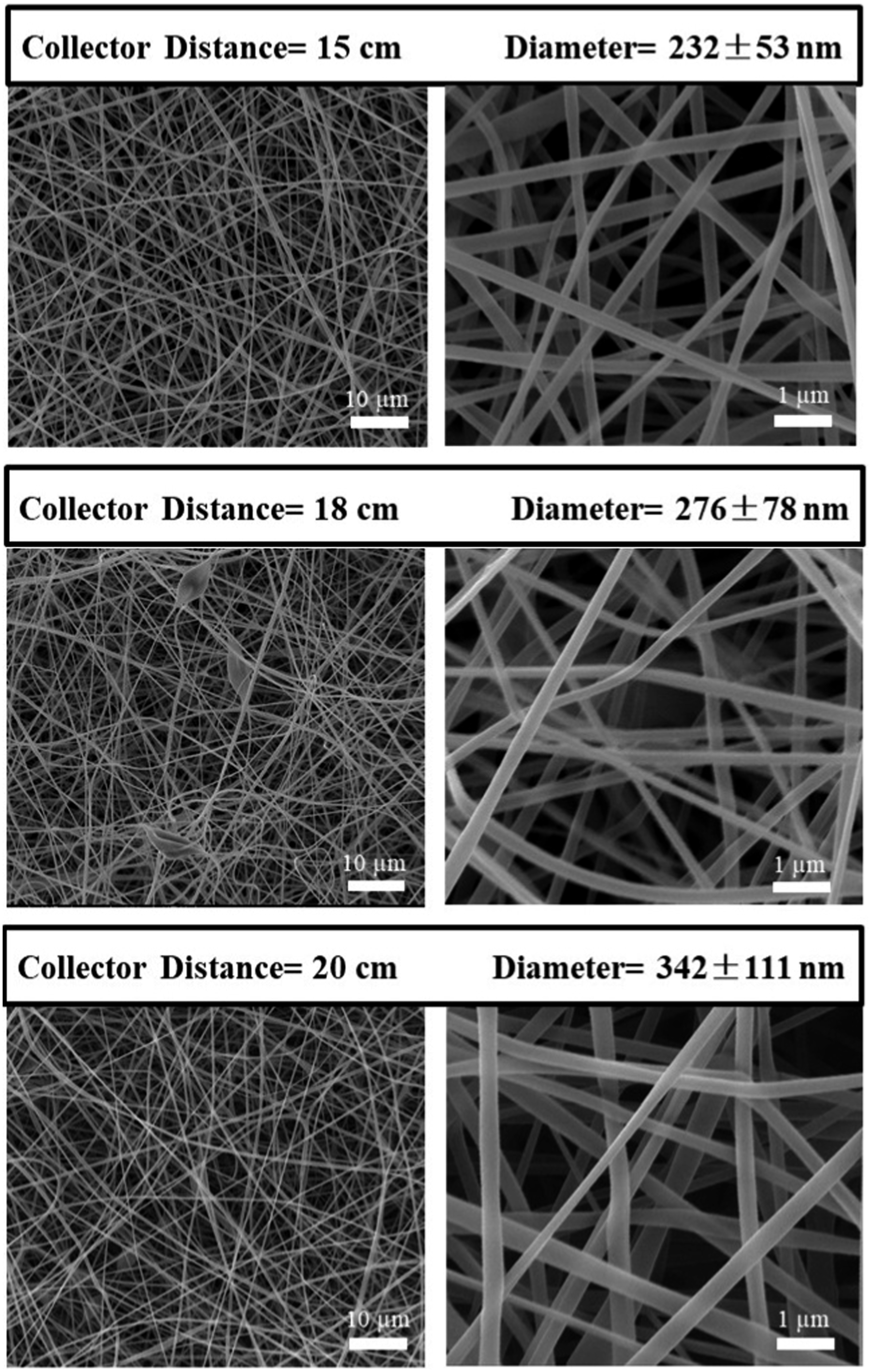
As revealed in Figures 7, 8, 9; it could be stated that to obtain rather bead-free and smooth PLA/CNF electrospun fibers with fine sized diameters; an optimum solution feeding rate and collector distance values of 1.5 mL/h and 15 cm could be used. It was observed that use of higher values resulted in larger diameters.
According to similar observations reported,31,38 it could be indicated that solution feeding rate and collector distance parameters significantly influence the balance of electrostatic repulsion, surface tension and viscoelastic forces in the electrospinning solution. They are all very critical conditions for the required solution jet velocity, solvent evaporation time and sufficient polymer transfer rate. When solution feeding rate and collector distance parameters are over an optimum value, then beaded morphology and larger diameter fiber formation would take place.
Effects of 3 wt% CNF use compared to 1 wt% on the diameter of electrospun fibers
In order to observe use of higher amount of nanocellulose particles on the diameter of electrospun fibers, this time PLA based electrospinning solution was prepared with 3 wt% CNF. Optimum processing parameters determined for the PLA solution with 1 wt% CNF discussed in the previous sections were applied without any change. Then, diameter analysis via SEM were conducted for each PLA/CNF electrospun fibers obtained. Figure 10 indicated that when polymer solution was filled with 3 wt% CNF compared to 1 wt% CNF, average diameter of electrospun fibers decreased significantly from 232 nm down to 175 nm. SEM images showing effects of higher CNF amount on the diameter of PLA/CNF electrospun fibers.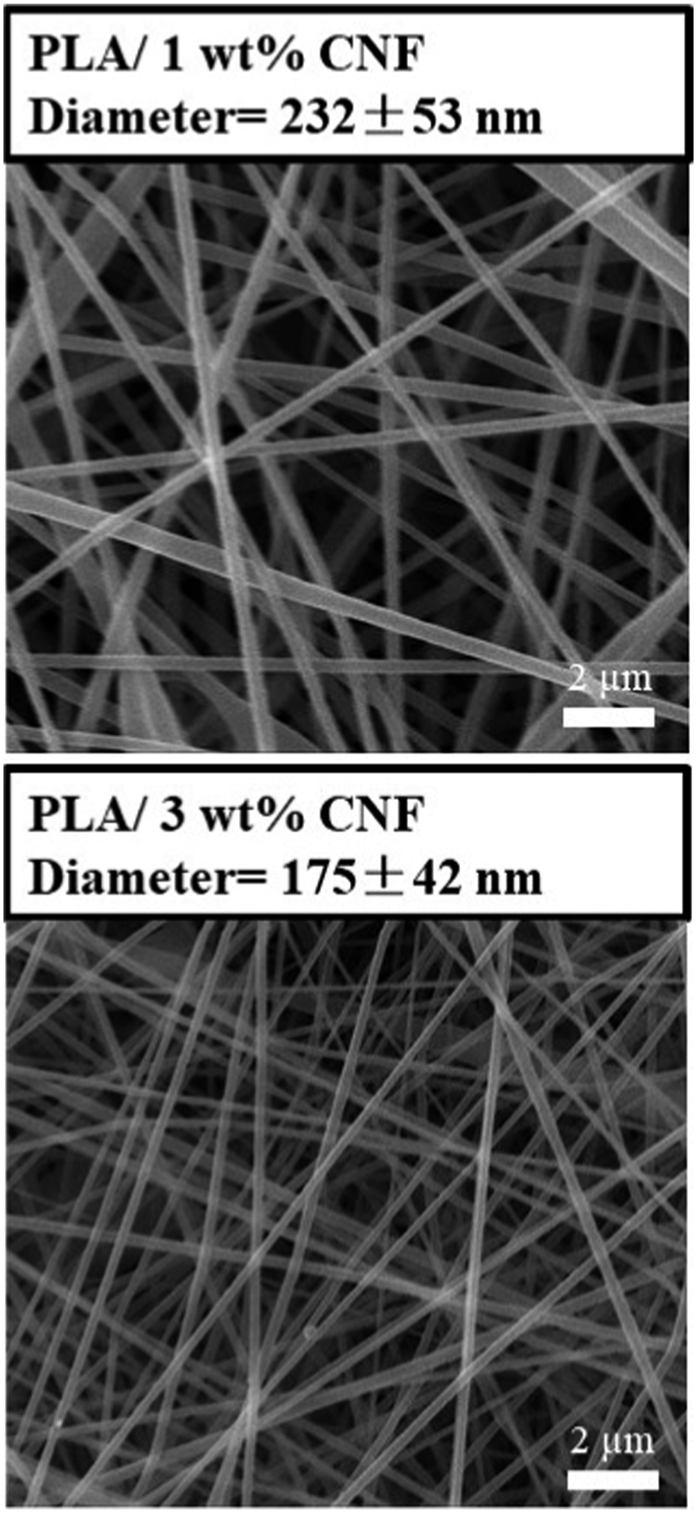
It is known that in the cellulose structure including CNF, there are plenty of hydroxyl groups which have the ability to increase charge density of the polymer solutions significantly. Thus, it was stated that22,23,26 higher charge density leads to increased electrostatic forces preventing the polymer solution jet to break into smaller segments. Consequently, formation of electrospun fibers with finer diameters was possible.
Thus, compared to 1 wt% CNF, use of 3 wt% CNF resulted in higher charge density in the electrospinning solution leading to much finer diameter distribution of PLA/CNF nanofibers obtained. On the other hand, effects of using more than 3 wt% CNF were not investigated. Although, several trials were conducted, due to the feeding tip clogging and other processing problems, it was difficult to obtain proper electrospun fiber morphology.
Effects of CNC use compared to CNF on the diameter of electrospun fibers
In order to compare whether there would be any difference when 1 wt% cellulose nanofibril (CNF) particles were replaced with 1 wt% cellulose nanocrystal (CNC) particles in the PLA solution, electrospinning experiments were repeated by using again the same optimum processing parameters to analyze and compare PLA/CNC electrospun fibers.
It was reported that26,28 apart from the extensive hydroxyl groups in the structure of all cellulose particles, additional sulfate ester groups would be present on the CNC surfaces; which were formed during H2SO4 acid hydrolysis technique used in their production. Consequently, charge density and electrical conductivity of PLA/CNC solution would be higher than the PLA/CNF solution, leading to finer diameter electrospun fibers as discussed above.
Thus, Figure 11 shows that due to higher conductivity of PLA/CNC solution (2.7 μS/cm) compared to conductivity of PLA/CNF solution (2.3 μS/cm); average PLA/CNC electrospun fiber diameter was 209 nm, while for PLA/CNF fibers it was 232 nm. SEM images showing effects of CNC use and KCl salt addition on the diameter of electrospun fibers.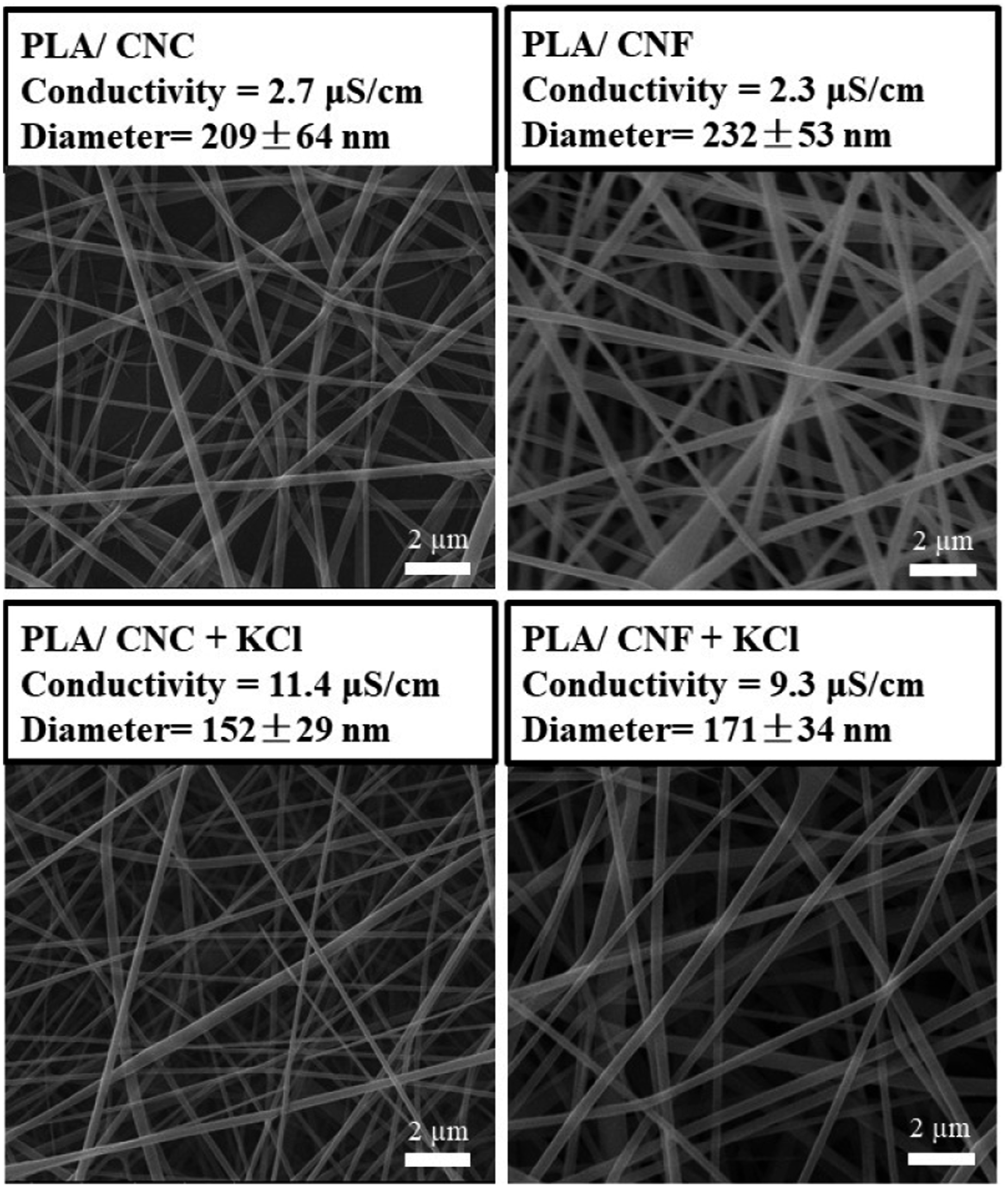
Effects of KCl salt addition on the diameter of electrospun fibers
Since higher charge density or conductivity of the polymer solution leads greater elongation forces and higher overall tension in the polymer solution jet resulting in bead-free fine diameter electrospun fibers; researchers29–31 investigated effects of organic or inorganic salt additions for various neat and filled PLA solutions, but not for PLA/CNC and PLA/CNF.
Thus, by using again the same processing parameters discussed before, electrospinning experiments for both PLA/CNC and PLA/CNF solutions were repeated this time by adding 3 wt% KCl salt into their solutions. It could be observed in Figure 11 that when KCl salt was added to PLA/CNC solution, its conductivity increased from 2.7 to 11.4 μS/cm leading to the finest average diameter of 152 nm. Similarly, conductivity of PLA/CNF solution was increased from 2.3 to 9.3 μS/cm again resulting in finer average diameter of 171 nm.
It should be noted that during diameter determination of electrospun nanofibers by the image analysis software, data were also evaluated statistically by drawing the “frequency-diameter histograms” to trace the variations. Two examples are given in Figure 12 drawn for the PLA/CNC+KCl and PLA/CNF+KCl nanofibers having the finest diameters in this study. Two examples of the frequency-diameter histograms determined for the PLA/CNC+KCl and PLA/CNF+KCl nanofibers.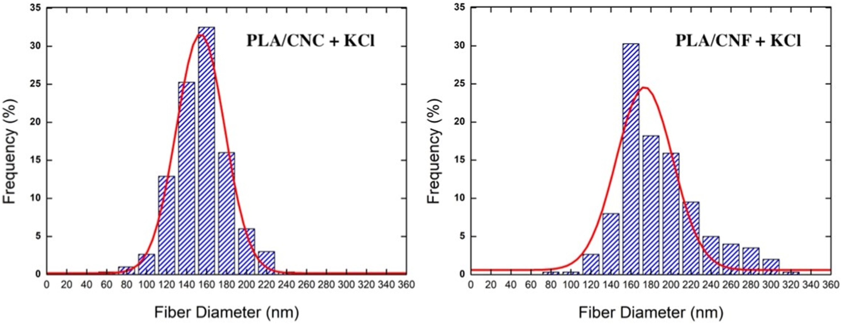
Effects of electrospun fiber diameters on the In Vitro degradation rate
It is known that biopolymer based electrospun fibers in mat or other forms have significant biomedical applications such as wound dressing; in which a controllable biodegradation rate would be required. Although in vitro degradation behavior of various neat and filled PLA based electrospun fiber mats were investigated,32–36 no study for PLA/CNF and only one study for PLA/CNC 28 was reported.
Therefore, according to the procedures explained in experimental work section, in vitro degradation rate of the electrospun fiber mats were investigated by immersing them in PBS simulated body fluid for 12 weeks. Apart from electrospun fiber mats of PLA/CNF, PLA/CNC, PLA/CNF + KCl and PLA/CNC + KCl; neat PLA samples were also produced and investigated for comparative reasons. Degradation degree in the mats was determined by measuring their “% weight loss” values after each week of PBS immersion. Figure 13 indicated that increasing the immersion period increased the degradation amount of all electrospun fiber mats. Increase of degradation degrees with increasing PBS immersion period for all electrospun fiber mats.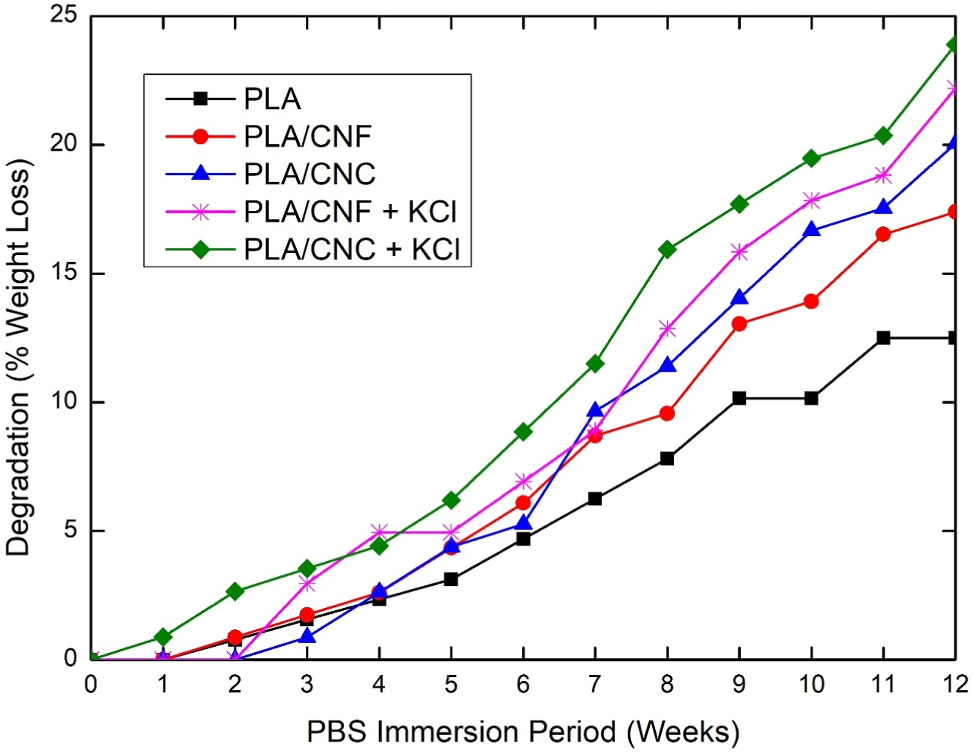
It is known that,32–34 the main degradation mechanism of PLA based materials in PBS solution was “hydrolysis” leading to cleavage of the ester backbone of PLA chains into carboxylate and hydroxyl groups. Although PLA is a hydrophobic biopolymer, cellulose nanostructures are hydrophilic; thus, immersion in PBS solution would increase in vitro degradation rate.
Effects of average fiber diameters on the in vitro degradation degree of all electrospun fiber mats after each month.
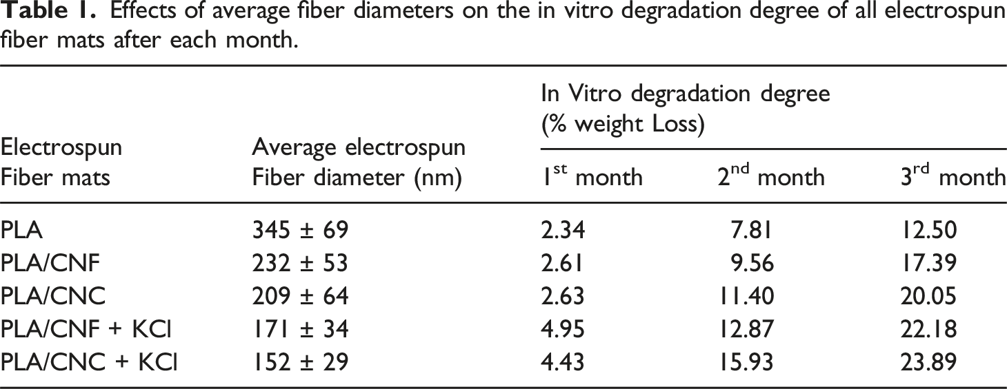
Table 1 revealed that decreasing the electrospun fiber diameter increased the in vitro degradation rate of their mats. For instance, after three months, neat PLA mat having largest average fiber diameter of 345 nm resulted in lowest degradation amount of 12.5 % weight loss; on the other hand, PLA/CNC + KCl mat having lowest average fiber diameter of 152 nm resulted in highest degradation degree with 23.9 % weight loss.
Conclusions
Main conclusions on the effects of various parameters influencing morphology and diameter of the nanofibers obtained via electrospinning of nanocelluse filled polylactide were as follows: • It was observed that when solution concentration of PLA/CNF was 8 %w/v (viscosity 124 cP); due to proper Taylor cone and stable solution jet formation, it was possible to obtain “fibrous” morphology rather than occurrence of droplets. • In order to obtain almost “bead-free” morphology and “finest” average diameter (232 nm) for these PLA/CNF electrospun fibers, several trials indicated that the best processing parameter combination for solution feeding rate and collector distance to feeding tip was 1.5 mL/h and 15 cm, respectively. Increasing values of these two parameters resulted in bead formation and thicker diameters. • When polymer solution was filled with 3 wt% CNF rather than 1 wt%, average diameter of electrospun fibers decreased significantly from 232 nm down to 175 nm. It was basically due to the higher amount of hydroxyl groups present in the cellulose structure resulting in increased charge density of the polymer solution. • When polymer solution was filled with 1 wt% CNC particles rather than 1 wt% CNF, average diameter of electrospun fibers decreased this time from 232 nm down to 209 nm. Because, additional sulfate ester groups present on CNC surfaces resulted in higher charge density and electrical conductivity of PLA/CNC solution (2.7 μS/cm) compared to conductivity of PLA/CNF solution (2.3 μS/cm). • When 3 wt% KCl salt was added into PLA/CNC and PLA/CNF solutions; then due to the additional increased electrical conductivities, their average electrospun fiber diameters further decreased down to 152 nm and 171 nm, respectively.
Moreover, in vitro degradation analysis of all electrospun fiber mats by immersing in a simulated body fluid revealed that increasing the immersion period increased their degradation rate in terms of “% weight loss”. Since decreasing the electrospun fiber diameter would increase their total surface area exposed, it was also observed that mats with fine diameter fibers had higher degradation rate.
Footnotes
Declaration of conflicting interests
The author(s) declared no potential conflicts of interest with respect to the research, authorship, and/or publication of this article.
Funding
The author(s) received no financial support for the research, authorship, and/or publication of this article.